Page 756 of 1575
6Rear temp S/W (FLOOR)
7 Rhostat (ILL- )
8 Sensor Ref (+5V)
9 Sensor ground
10 Rear mode IND (VENT)
11 Rear mode IND (B/L)
12 Rear mode IND (FLOOR)
13 GND
14 -
15 -
16 Rear blower S/W
Page 782 of 1575
2007 > 2.7L V6 GASOLINE >
COMPONENT
CONNECTOR PIN FUNCTION
PIN NO. Function PIN NO. Function
1 BATTERY 7-
2 IGN 2 8POWER MOSFET (GATE) - REAR
3 TAIL LAMP (ILL+) 9POWER MOSFET (DRAIN) -
REAR
4 REAR TEMP ACTUATOR
(COOL) 10
-
5 REAR TEMP ACTUATOR
(WARM) 11
SENSOR GND
Page 783 of 1575

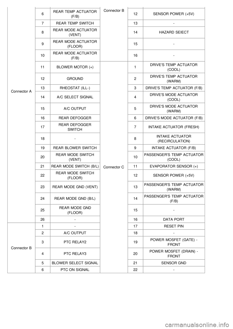
Connector AConnector B
6 REAR TEMP ACTUATOR
(F/B) 12
SENSOR POWER (+5V)
7 REAR TEMP SWITCH 13-
8 REAR MODE ACTUATOR
(VENT) 14
HAZARD SEIECT
9 REAR MODE ACTUATOR
(FLOOR) 15
-
10 REAR MODE ACTUATOR
(F/B) 16
-
11 BLOWER MOTOR (+)
Connector C1
DRIVE'S TEMP ACTUATOR
(COOL)
12 GROUND 2DRIVE'S TEMP ACTUATOR
(WARM)
13 RHEOSTAT (ILL- ) 3DRIVE'S TEMP ACTUATOR (F/B)
14 A/C SELECT SIGNAL 4DRIVE'S MODE ACTUATOR
(COOL)
15 A/C OUTPUT 5DRIVE'S MODE ACTUATOR
(WARM)
16 REAR DEFOGGER 6DRIVE'S MODE ACTUATOR (F/B)
17 REAR DEFOGGER
SWITCH 7
INTAKE ACTUATOR (FRESH)
18 - 8INTAKE ACTUATOR
(RECIRCULATION)
19 REAR BLOWER SWITCH 9INTAKE ACTUATOR (F/B)
20 REAR MODE SWITCH
(VENT) 10
PASSENGER'S TEMP ACTUATOR
(COOL)
21 REAR MODE SWITCH (B/L) 11EVAPORATOR SENSOR (+)
22 REAR MODE SWITCH
(FLOOR) 12
SENSOR POWER (+5V)
23 REAR MODE GND (VENT) 13PASSENGER'S TEMP ACTUATOR
(WARM)
24 REAR MODE GND (B/L) 14PASSENGER'S TEMP ACTUATOR
(F/B)
25 REAR MODE GND
(FLOOR) 15
-
26 - 16DATA PORT
Connector B 1
- 17RESET PIN
2 A/C OUTPUT 18-
3 PTC RELAY2 19POWER MOSFET (GATE) -
FRONT
4 PTC RELAY3 20POWER MOSFET (DRAIN) -
FRONT
5 BLOWER SELECT SIGNAL 21SENSOR GND
6 PTC ON SIGNAL 22-
Page 786 of 1575
2007 > 2.7L V6 GASOLINE >
COMPONENT
CONNECTOR PIN FUNCTION
PIN NO. Function PIN NO. Function
1 BATTERY 7-
2 IGN 2 8POWER MOSFET (GATE) - REAR
3 TAIL LAMP (ILL+) 9POWER MOSFET (DRAIN) -
REAR
4 REAR TEMP ACTUATOR
(COOL) 10
-
5 REAR TEMP ACTUATOR
(WARM) 11
SENSOR GND
Page 787 of 1575

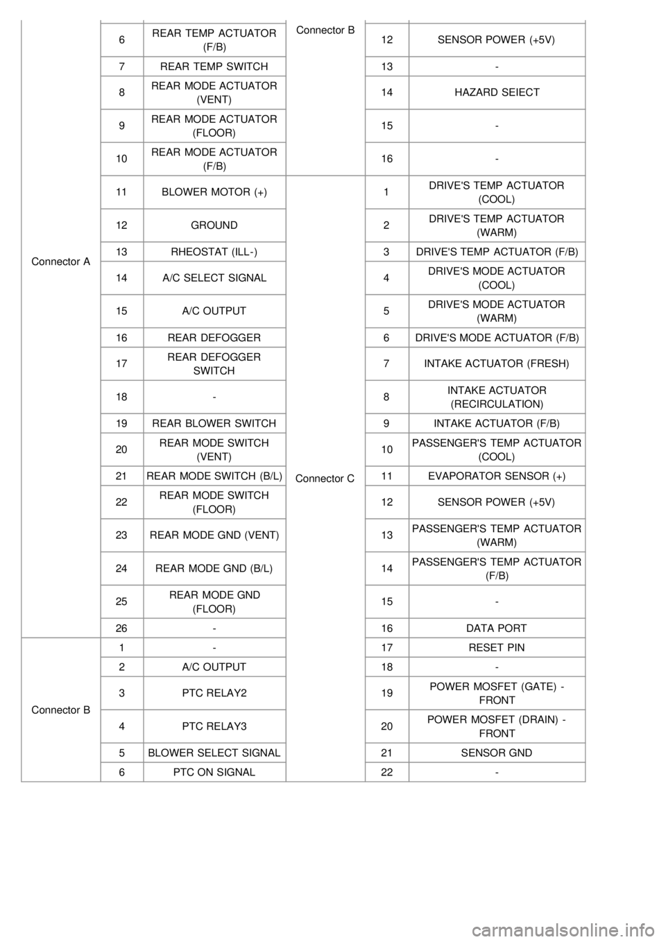
Connector AConnector B
6 REAR TEMP ACTUATOR
(F/B) 12
SENSOR POWER (+5V)
7 REAR TEMP SWITCH 13-
8 REAR MODE ACTUATOR
(VENT) 14
HAZARD SEIECT
9 REAR MODE ACTUATOR
(FLOOR) 15
-
10 REAR MODE ACTUATOR
(F/B) 16
-
11 BLOWER MOTOR (+)
Connector C1
DRIVE'S TEMP ACTUATOR
(COOL)
12 GROUND 2DRIVE'S TEMP ACTUATOR
(WARM)
13 RHEOSTAT (ILL- ) 3DRIVE'S TEMP ACTUATOR (F/B)
14 A/C SELECT SIGNAL 4DRIVE'S MODE ACTUATOR
(COOL)
15 A/C OUTPUT 5DRIVE'S MODE ACTUATOR
(WARM)
16 REAR DEFOGGER 6DRIVE'S MODE ACTUATOR (F/B)
17 REAR DEFOGGER
SWITCH 7
INTAKE ACTUATOR (FRESH)
18 - 8INTAKE ACTUATOR
(RECIRCULATION)
19 REAR BLOWER SWITCH 9INTAKE ACTUATOR (F/B)
20 REAR MODE SWITCH
(VENT) 10
PASSENGER'S TEMP ACTUATOR
(COOL)
21 REAR MODE SWITCH (B/L) 11EVAPORATOR SENSOR (+)
22 REAR MODE SWITCH
(FLOOR) 12
SENSOR POWER (+5V)
23 REAR MODE GND (VENT) 13PASSENGER'S TEMP ACTUATOR
(WARM)
24 REAR MODE GND (B/L) 14PASSENGER'S TEMP ACTUATOR
(F/B)
25 REAR MODE GND
(FLOOR) 15
-
26 - 16DATA PORT
Connector B 1
- 17RESET PIN
2 A/C OUTPUT 18-
3 PTC RELAY2 19POWER MOSFET (GATE) -
FRONT
4 PTC RELAY3 20POWER MOSFET (DRAIN) -
FRONT
5 BLOWER SELECT SIGNAL 21SENSOR GND
6 PTC ON SIGNAL 22-
Page 792 of 1575

c.Store the removed airbag on secure, flat surface away from any high heat source (exceeding 85°C/185°F).
d. Never perform electrical inspections to the airbags, such as measuring resistance.
e. Do not position yourself in front of the airbag assembly during removal, inspection, or replacement.
f. Refer to the scrapping procedures for disposal of the damaged airbag.
g. Be careful not to bump or impact the SRS unit or the side impact sensors whenever the ignition switch is ON, wait
at least three minutes after the ignition switch is turned OFF before begin work.
h. During installation or replacement, be careful not to bump (by impact wrench, hammer, etc.) the area around the
SRS unit and the side impact sensor. The airbags could accidentally deploy and cause damage or injury.
i. After a collision in which the airbags were deployed, replace the front airbags and the SRS unit. After a collision in
which the side airbag was deployed, replace the side airbag, the front impact sensor and side impact sensor on
the side where the side airbag deployed and the SRS unit. After a collision in which the airbags or the side air
bags did not deploy, inspect for any damage or any deformation on the SRS unit and the side impact sensors. If
there is any damage, replace the SRS unit, the front impact sensor and/or the side impact sensors.
j. Do not disassemble the SRS unit, the front impact sensor or the side impact sensors
k. Turn the ignition switch OFF, disconnect the battery negative cable and wait at least three minutes before
beginning installation or replacement of the SRS unit.
l. Be sure the SRS unit, the front impact sensor and side impact sensors are installed securely with the mounting
bolts.
m. Do not spill water or oil on the SRS unit,or the front impact sensor or the side impact sensors and keep them
away from dust.
n. Store the SRS unit, the front impact sensor and the side impact sensors in a cool (less than 40°C/104°F) and dry
(less than 80% relative humidity, no moisture) area.
Wiring Precautions
SRS wiring can be identified by special yellow outer covering (except the SRS circuits under the front seats).
Observe the instructions described in this section.
a. Never attempt to modify, splice, or repair SRS wiring.
If there is an open or damage in SRS wiring, replace the harness.
Page 795 of 1575

2007 > 2.7L V6 GASOLINE >
General
The supplemental restraint system (SRS) is designed to supplement the seat belt to help reduce the risk or severity of
injury to the driver and passenger by activating and deploying the driver, passenger, side airbag and belt pretensioner
in certain frontal or side collisions.
The SRS (Airbag) consists of : a driver side airbag module located in the center of the steering wheel, which contains
the folded cushion and an inflator unit ; a passenger side airbag module located in the passenger side crash pad
contains the folded cushion assembled with inflator unit ; side airbag modules located in the driver and passenger seat
contain the folded cushion and an inflator unit ; curtain airbag modules located inside of the headliner which contains
folded cushions and inflator units. The impact sensing function of the SRSCM is carried out by electronic
accelerometer that continuously measure the vehicle's acceleration and delivers a corresponding signal through
amplifying and filtering circuitry to the microprocessor.
SRSCM (SRS Control Module)
SRSCM will detect front impact with front impact sensor, and side impact with side impact sensor, and determine
airbag module deployment.
1. DC/DC converter: DC/DC converter in power supply unit includes up/down transformer converter, and provide
ignition voltage for 2 front airbag ignition circuits and the internal operation voltage of the SRSCM. If the internal
operation voltage is below critical value setting, it will perform resetting.
2. Safety sensor: Safety sensor is located in airbag ignition circuit. Safety sensor will operate airbag circuit at any
deployment condition and release airbag circuit safely at normal driving condition. Safety sensor is a double contact
electro - mechanical switch that will close detecting deceleration above certain criteria.
3. Back up power supply: SRSCM has separate back up power supply, that will supply deployment energy instantly in
low voltage condition or upon power failure by front crash.
4. Self diagnosis: SRSCM will constantly monitor current SRS operation status and detect system failure while vehicle
power supply is on, system failure may be checked with trouble codes using scan tool. (Hi- Scan)
5. Airbag warning lamp on: Upon detecting error, the module will transmit signal to SRSCM indicator lamp located at
cluster. MIL lamp will indicate driver SRS error. Upon ignition key on, SRS lamp will turn on for about six seconds.
6. Trouble code registration: Upon error occurrence in system, SRSCM will store DTC corresponding to the error.
DTC can be cleared only by Hi - Scan. However, if an internal fault code is logged or if a crash is recorded the fault
clearing should not happen.
7. Self diagnostic connector: Data stored in SRSCM memory will be output to Hi - Scan or other external output
devices through connector located below driver side crash pad.
8. Once airbag is deployed, SRSCM should not be used again but replaced.
9. SRSCM will determine whether passenger put on seat belt by the signal from built- in switch in seat belt buckle, and
deploy front seat airbag at each set crash speed.
10. Side airbag deployment will be determined by SRSCM that will detect satellite sensor impact signal upon side
crash, irrespective to seat belt condition.
Page 801 of 1575
SEAT BELT BUCKLE PRETENSIONER (BUPT)
SIDE IMPACT SENSOR (SIS)