Page 837 of 1575
4.Check airbag inflator case for dents, cracks or deformities.
5.Install the airbag module to the steering wheel to check for fit or alignment with the wheel.
Clockspring
1.If, as a result of the following checks, even one abnormal point is discovered, replace the clock spring with a new
one.
2. Check connectors and protective tube for damage, and terminals for deformities.
Page 853 of 1575
2007 > 2.7L V6 GASOLINE >
DESCRIPTION
The Seat Belt Pretensioners (BPT) are installed inside Center Pillar (LH & RH). When a vehicle crashes with a certain
degree of frontal impact, the pretensioner seat belt helps to reduce the severity of injury to the front seat occupants by
retracting the seat belt webbing. This prevents the front occupants from thrusting forward and hitting the steering
wheel or the instrument panel when the vehicle crashes.
Never attempt to measure the circuit resistance of the Seat Belt Pretensioner (BPT) even if you are using the
specified tester. If the circuit resistance is measured with a tester, the pretensioner will be ignited accidentally.
This will result in serious personal injury.
Page 857 of 1575
2007 > 2.7L V6 GASOLINE >
DESCRIPTION
The Seat Belt Buckle Pretensioners (BUPT) are installed in the right side of the driver seat and the left side of the
passenger seat. When a vehicle crashes with a certain degree of frontal impact, the seat belt buckle pretensioner
helps to reduce the severity of injury to the front seat occupants by retracting the seat belt buckle. This prevents the
front occupants from thrusting forward and hitting the steering wheel or the instrument panel when the vehicle crashes.
Never attempt to measure the circuit resistance of the Seat Belt Buckle Pretensioner (BUPT) even if you are
using the specified tester. If the circuit resistance is measured with a tester, the pretensioner will be ignited
accidentally. This will result in serious personal injury.
Page 864 of 1575
e.master cylinder cap seal
f. damaged brake lines replace
replace
Brake Chatter Brake chatter is usually caused by loose or worn components, or
glazed or burnt linings. Rotors with hard spots can also contribute to
brake chatter. Additional causes of chatter are out - of- tolerance rotors,
brake lining not securely attached to the shoes, loose wheel bearings
and contaminated brake lining.
Page 866 of 1575

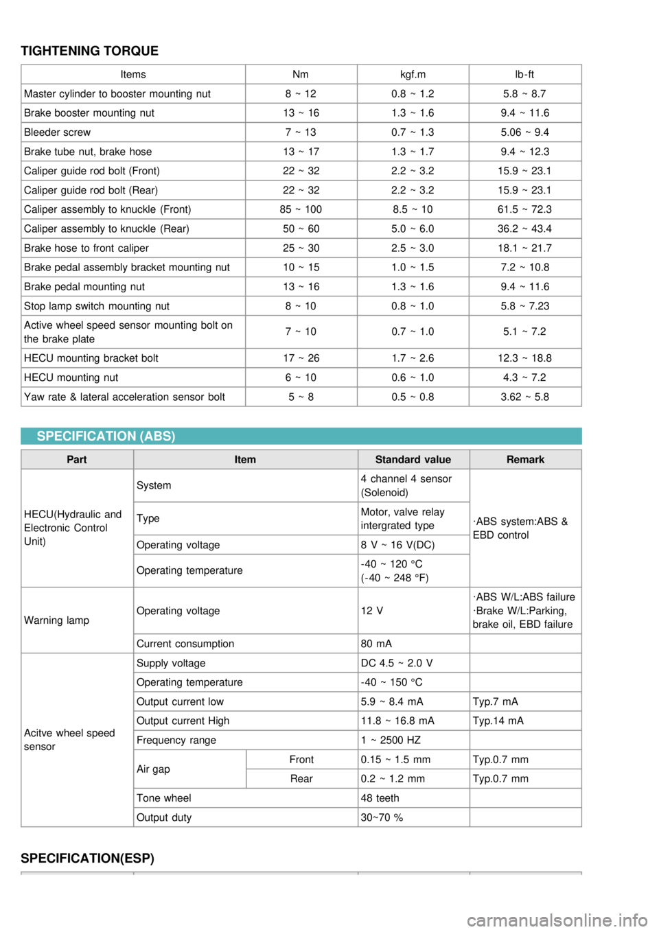
TIGHTENING TORQUE
ItemsNmkgf.m lb - ft
Master cylinder to booster mounting nut 8 ~ 120.8 ~ 1.2 5.8 ~ 8.7
Brake booster mounting nut 13 ~ 161.3 ~ 1.6 9.4 ~ 11.6
Bleeder screw 7 ~ 130.7 ~ 1.3 5.06 ~ 9.4
Brake tube nut, brake hose 13 ~ 171.3 ~ 1.7 9.4 ~ 12.3
Caliper guide rod bolt (Front) 22 ~ 322.2 ~ 3.215.9 ~ 23.1
Caliper guide rod bolt (Rear) 22 ~ 322.2 ~ 3.215.9 ~ 23.1
Caliper assembly to knuckle (Front) 85 ~ 1008.5 ~ 1061.5 ~ 72.3
Caliper assembly to knuckle (Rear) 50 ~ 605.0 ~ 6.036.2 ~ 43.4
Brake hose to front caliper 25 ~ 302.5 ~ 3.018.1 ~ 21.7
Brake pedal assembly bracket mounting nut 10 ~ 151.0 ~ 1.5 7.2 ~ 10.8
Brake pedal mounting nut 13 ~ 161.3 ~ 1.6 9.4 ~ 11.6
Stop lamp switch mounting nut 8 ~ 100.8 ~ 1.0 5.8 ~ 7.23
Active wheel speed sensor mounting bolt on
the brake plate 7 ~ 10
0.7 ~ 1.0 5.1 ~ 7.2
HECU mounting bracket bolt 17 ~ 261.7 ~ 2.612.3 ~ 18.8
HECU mounting nut 6 ~ 100.6 ~ 1.0 4.3 ~ 7.2
Yaw rate & lateral acceleration sensor bolt 5 ~ 80.5 ~ 0.8 3.62 ~ 5.8
SPECIFICATION (ABS)
Part ItemStandard valueRemark
HECU(Hydraulic and
Electronic Control
Unit) System
4 channel 4 sensor
(Solenoid)
·ABS system:ABS &
EBD control
Type
Motor, valve relay
intergrated type
Operating voltage 8 V ~ 16 V(DC)
Operating temperature - 40 ~ 120 °C
( - 40 ~ 248 °F)
Warning lamp Operating voltage
12 V·ABS W/L:ABS failure
·Brake W/L:Parking,
brake oil, EBD failure
Current consumption 80 mA
Acitve wheel speed
sensor Supply voltage
DC 4.5 ~ 2.0 V
Operating temperature - 40 ~ 150 °C
Output current low 5.9 ~ 8.4 mATyp.7 mA
Output current High 11.8 ~ 16.8 mATyp.14 mA
Frequency range 1 ~ 2500 HZ
Air gap Front
0.15 ~ 1.5 mm Typ.0.7 mm
Rear 0.2 ~ 1.2 mm Typ.0.7 mm
Tone wheel 48 teeth
Output duty 30~70 %
SPECIFICATION(ESP)
Page 867 of 1575

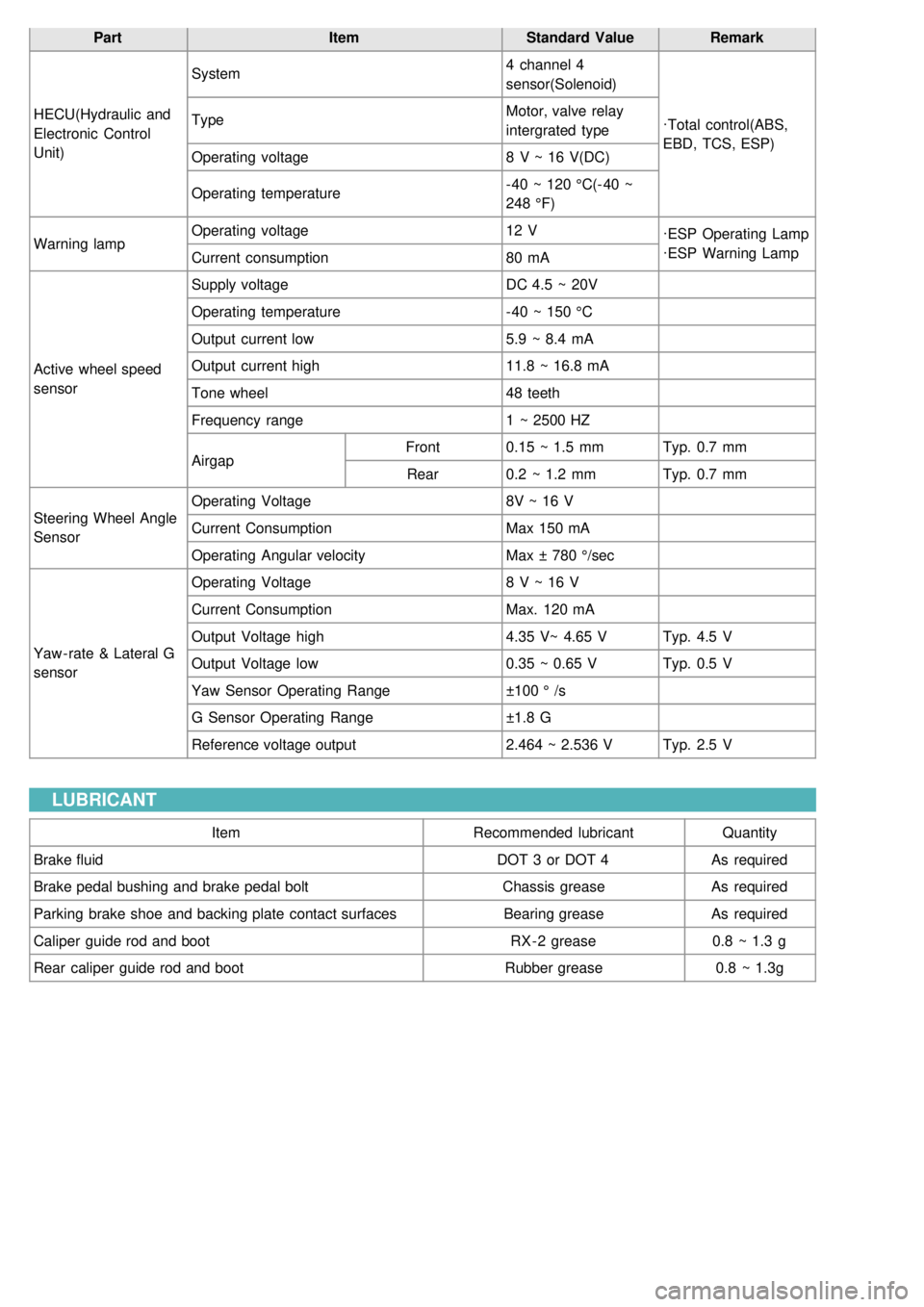
PartItemStandard ValueRemark
HECU(Hydraulic and
Electronic Control
Unit) System
4 channel 4
sensor(Solenoid)
·Total control(ABS,
EBD, TCS, ESP)
Type
Motor, valve relay
intergrated type
Operating voltage 8 V ~ 16 V(DC)
Operating temperature - 40 ~ 120 °C(- 40 ~
248 °F)
Warning lamp Operating voltage
12 V
·ESP Operating Lamp
·ESP Warning Lamp
Current consumption 80 mA
Active wheel speed
sensor Supply voltage
DC 4.5 ~ 20V
Operating temperature - 40 ~ 150 °C
Output current low 5.9 ~ 8.4 mA
Output current high 11.8 ~ 16.8 mA
Tone wheel 48 teeth
Frequency range 1 ~ 2500 HZ
Airgap Front
0.15 ~ 1.5 mm Typ. 0.7 mm
Rear 0.2 ~ 1.2 mm Typ. 0.7 mm
Steering Wheel Angle
Sensor Operating Voltage
8V ~ 16 V
Current Consumption Max 150 mA
Operating Angular velocity Max ± 780 °/sec
Yaw - rate & Lateral G
sensor Operating Voltage
8 V ~ 16 V
Current Consumption Max. 120 mA
Output Voltage high 4.35 V~ 4.65 VTyp. 4.5 V
Output Voltage low 0.35 ~ 0.65 VTyp. 0.5 V
Yaw Sensor Operating Range ±100 ° /s
G Sensor Operating Range ±1.8 G
Reference voltage output 2.464 ~ 2.536 VTyp. 2.5 V
LUBRICANT
Item Recommended lubricantQuantity
Brake fluid DOT 3 or DOT 4As required
Brake pedal bushing and brake pedal bolt Chassis greaseAs required
Parking brake shoe and backing plate contact surfaces Bearing greaseAs required
Caliper guide rod and boot RX - 2 grease0.8 ~ 1.3 g
Rear caliper guide rod and boot Rubber grease0.8 ~ 1.3g
Page 899 of 1575
2007 > 2.7L V6 GASOLINE >
REMOVAL
Frequent inhalation of brake pad dust, regardless of material composition, could be hazardous to your health.
a. Avoid breathing dust particles.
b. Never use on air hose or brush to clean brake assemblies.
1. Loosen the front wheel nuts slightly. Raise the front of the vehicle, and make sure it is securely supported. Remove
the front wheels.
2. Remove the guide rod bolt (B), After raise the caliper assembly (A), support it with a wire.
3.Remove pad shim (A), pad retainer (B) and pad assembly (C) in the caliper bracket.
INSTALLATION
1.Install the pad retainers (A) on the caliper bracket.
2.Install pad shims (A) and the brake pads (B) with the wear indicator on the inside.
Page 905 of 1575
2007 > 2.7L V6 GASOLINE >
REMOVAL
1.Raise the rear of the vehicle and make sure it is securely supported. Remove the rear wheel.
2. Remove the guide rod bolt(B), After raising the caliper assembly (A), support it with a wire.
3.Remove pad shim (A), pad retainer (B) and pad assembly (C) in the caliper bracket.
INSTALLATION
1.Install the pad retainer (A) to the caliper bracket.
2. Install the brake pads (B) and pad shims (A) and Install the pad with the wear indicator (C) on the inside.
If you reuse the pads, check for foreign material between the pad shim (A) and the back of the pads (B) and
reinstall the brake pads in their original position to prevent a momentary loss of braking efficiency.
3. Press in the piston with the special tool (09581- 11000).