Page 1237 of 1575

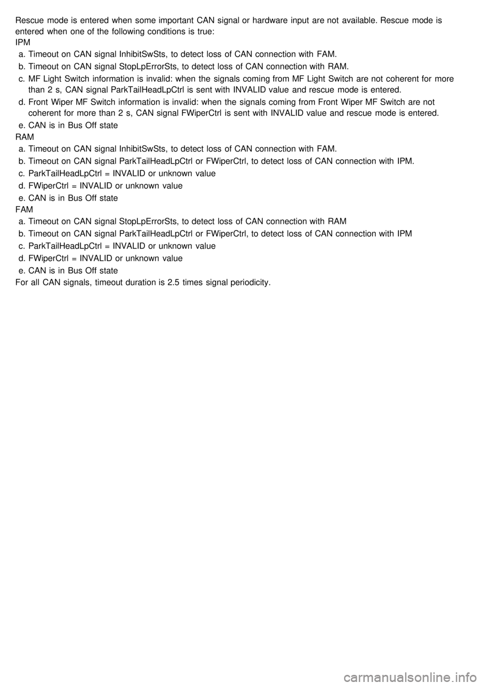
Rescue mode is entered when some important CAN signal or hardware input are not available. Rescue mode is
entered when one of the following conditions is true:
IPMa. Timeout on CAN signal InhibitSwSts, to detect loss of CAN connection with FAM.
b. Timeout on CAN signal StopLpErrorSts, to detect loss of CAN connection with RAM.
c. MF Light Switch information is invalid: when the signals coming from MF Light Switch are not coherent for more
than 2 s, CAN signal ParkTailHeadLpCtrl is sent with INVALID value and rescue mode is entered.
d. Front Wiper MF Switch information is invalid: when the signals coming from Front Wiper MF Switch are not
coherent for more than 2 s, CAN signal FWiperCtrl is sent with INVALID value and rescue mode is entered.
e. CAN is in Bus Off state
RAM a. Timeout on CAN signal InhibitSwSts, to detect loss of CAN connection with FAM.
b. Timeout on CAN signal ParkTailHeadLpCtrl or FWiperCtrl, to detect loss of CAN connection with IPM.
c. ParkTailHeadLpCtrl = INVALID or unknown value
d. FWiperCtrl = INVALID or unknown value
e. CAN is in Bus Off state
FAM a. Timeout on CAN signal StopLpErrorSts, to detect loss of CAN connection with RAM
b. Timeout on CAN signal ParkTailHeadLpCtrl or FWiperCtrl, to detect loss of CAN connection with IPM
c. ParkTailHeadLpCtrl = INVALID or unknown value
d. FWiperCtrl = INVALID or unknown value
e. CAN is in Bus Off state
For all CAN signals, timeout duration is 2.5 times signal periodicity.
Page 1244 of 1575

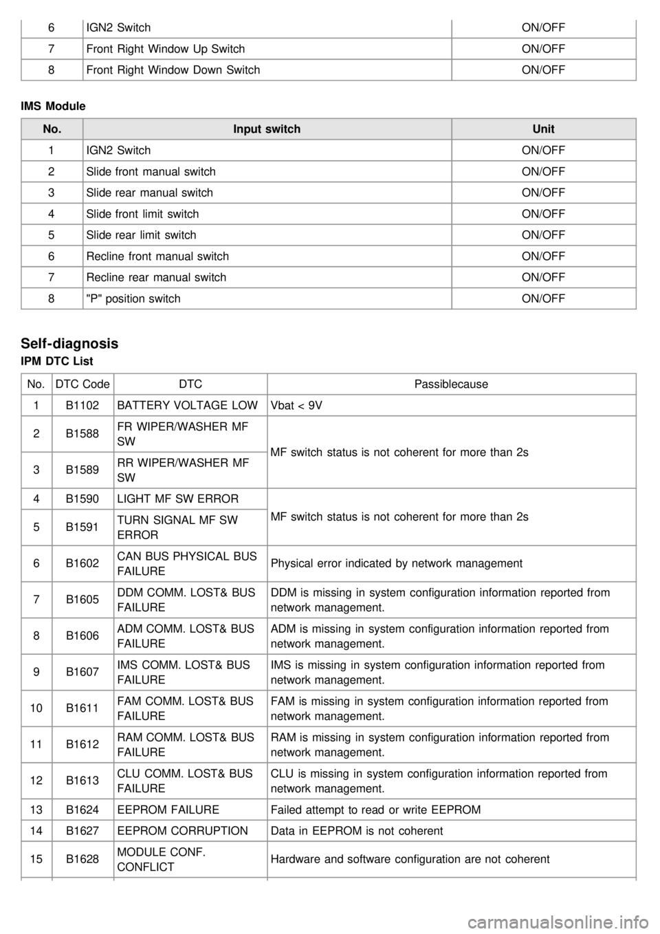
6IGN2 Switch ON/OFF
7 Front Right Window Up Switch ON/OFF
8 Front Right Window Down Switch ON/OFF
IMS Module No. Input switch Unit
1 IGN2 Switch ON/OFF
2 Slide front manual switch ON/OFF
3 Slide rear manual switch ON/OFF
4 Slide front limit switch ON/OFF
5 Slide rear limit switch ON/OFF
6 Recline front manual switch ON/OFF
7 Recline rear manual switch ON/OFF
8 "P" position switch ON/OFF
Self-diagnosis
IPM DTC List
No. DTC Code DTC Passiblecause
1 B1102 BATTERY VOLTAGE LOW Vbat < 9V
2 B1588 FR WIPER/WASHER MF
SW
MF switch status is not coherent for more than 2s
3 B1589 RR WIPER/WASHER MF
SW
4 B1590 LIGHT MF SW ERROR
MF switch status is not coherent for more than 2s
5 B1591 TURN SIGNAL MF SW
ERROR
6 B1602 CAN BUS PHYSICAL BUS
FAILURE Physical error indicated by network management
7 B1605 DDM COMM. LOST& BUS
FAILURE DDM is missing in system configuration information reported from
network management.
8 B1606 ADM COMM. LOST& BUS
FAILURE ADM is missing in system configuration information reported from
network management.
9 B1607 IMS COMM. LOST& BUS
FAILURE IMS is missing in system configuration information reported from
network management.
10 B1611 FAM COMM. LOST& BUS
FAILURE FAM is missing in system configuration information reported from
network management.
11 B1612 RAM COMM. LOST& BUS
FAILURE RAM is missing in system configuration information reported from
network management.
12 B1613 CLU COMM. LOST& BUS
FAILURE CLU is missing in system configuration information reported from
network management.
13 B1624 EEPROM FAILURE Failed attempt to read or write EEPROM
14 B1627 EEPROM CORRUPTION Data in EEPROM is not coherent
15 B1628 MODULE CONF.
CONFLICT Hardware and software configuration are not coherent
Page 1248 of 1575

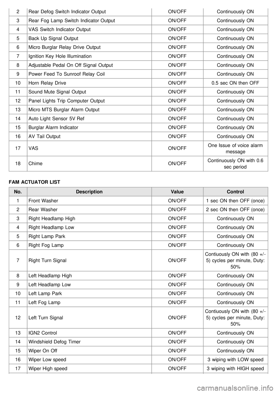
2Rear Defog Switch Indicator Output ON/OFFContinuously ON
3 Rear Fog Lamp Switch Indicator Output ON/OFFContinuously ON
4 VAS Switch Indicator Output ON/OFFContinuously ON
5 Back Up Signal Output ON/OFFContinuously ON
6 Micro Burglar Relay Drive Output ON/OFFContinuously ON
7 Ignition Key Hole Illumination ON/OFFContinuously ON
8 Adjustable Pedal On Off Signal Output ON/OFFContinuously ON
9 Power Feed To Sunroof Relay Coil ON/OFFContinuously ON
10 Horn Relay Drive ON/OFF0.5 sec ON then OFF
11 Sound Mute Signal Output ON/OFFContinuously ON
12 Panel Lights Trip Computer Output ON/OFFContinuously ON
13 Micro MTS Burglar Alarm Output ON/OFFContinuously ON
14 Auto Light Sensor 5V Ref ON/OFFContinuously ON
15 Burglar Alarm Indicator ON/OFFContinuously ON
16 AV Tail Output ON/OFFContinuously ON
17 VAS ON/OFFOne Issue of voice alarm
message
18 Chime ON/OFFContinuously ON with 0.6
sec period
FAM ACTUATOR LIST No. Description ValueControl
1 Front Washer ON/OFF1 sec ON then OFF (once)
2 Rear Washer ON/OFF2 sec ON then OFF (once)
3 Right Headlamp High ON/OFFContinuously ON
4 Right Headlamp Low ON/OFFContinuously ON
5 Right Lamp Park ON/OFFContinuously ON
6 Right Fog Lamp ON/OFFContinuously ON
7 Right Turn Signal ON/OFFContiuously ON with (80 +/ -
5) cycles per minute, Duty: 50%
8 Left Headlamp High ON/OFFContinuously ON
9 Left Headlamp Low ON/OFFContinuously ON
10 Left Lamp Park ON/OFFContinuously ON
11 Left Fog Lamp ON/OFFContinuously ON
12 Left Turn Signal ON/OFFContiuously ON with (80 +/ -
5) cycles per minute, Duty: 50%
13 IGN2 Control ON/OFFContinuously ON
14 Windshield Defog Timer ON/OFFContinuously ON
15 Wiper On Off ON/OFFContinuously ON
16 Wiper Low speed ON/OFF3 wiping with LOW speed
17 Wiper High speed ON/OFF3 wiping with HIGH speed
Page 1310 of 1575
4.Connect the oil pressure switch wire harness.
5. Turn the ignition switch ON. Check that the warning lamp lights up. If the warning lamp doesn't light, test the wire
harness.
BRAKE FLUID LEVEL WARNING SWITCH
1.Remove the connector (A) from the switch located at the brake fluid reservoir (B).
2. Verify that continuity exists between switch terminals 1 and 2 while pressing the switch (float) down with a rod.
BRAKE FLUID LEVEL WARNING LAMP
1.Ignition "ON"
2. Release the parking brake.
3. Remove the connector from the brake fluid level warning switch.
4. Ground the connector at the harness side.
5. Verify that the warning lamp lights.
PARKING BRAKE SWITCH
The parking brake switch is a push type. It is located at the side of the parking brake pedal.
1. Check that there is continuity between the terminal and switch body with the switch (A) ON.
Page 1329 of 1575
N(Neutral) for manual transaxle, P(Park) for automatic transaxle.
2. Door position
If the power sliding door is operated while the door is in slightly- opened position (less than 300mm), the door is
automatically opened fully. If the power sliding door is operated while the door is in slightly- opened position (more
than 300mm), the door is automatically closed completely.
3. If the door handle is pulled from inside or outside while the door is locked or child safety lock is engaged, the
power sliding door is not opened.
Page 1447 of 1575
2007 > 2.7L V6 GASOLINE >
DESCRIPTION
The electrochromatic rear view mirror detects the ambient light using a built- in sensor and adjusts the reflectability of
the mirror to prevent excess light (such as the light emitted by a following vehicle's headlights) from reaching the
driver's eyes during night driving. To allow for maximum vision while backing up, the electrochromatic functionality of
the mirror is deactivated whenever the transaxle is in 'R' range.
1.The front sensor sees if the brightness of the surroundings is low enough for the mirror to operate its function.
2. The rearward looking sensor detects glaring of the reflecting light from a following vehicle.
3. The ECM is darkened to the level as determined by the rearward looking sensor. When the glaring is no longer
detected, the mirror stops functioning.
Page 1448 of 1575
2007 > 2.7L V6 GASOLINE >
INSPECTION
Check it by the procedure below to see if the function of the ECM is normal.
1. Turn the ignition key to the "ON" position.
2. Cover the front sensor to stop functioning.
3. Shine a light at the rear sensor.
4. The ECM should be darkened as soon as the rear sensor detects the light.
If this test is performed in daytime, the mirror may be darkened as soon as the looking sensor is covered.
5. When the reverse gear is engaged, the ECM should not be darkened.
REPLACEMENT
1.Push the inside rear view mirror base down to remove the inside rear view mirror assembly (A) after removing the
mirror wire cover.
Take care not to damage the mounting bracket during removal.
2.Installation is the reverse of removal.
Page 1464 of 1575
2007 > 2.7L V6 GASOLINE >
REPLACEMENT
1.Disconnect the negative ( - ) battery terminal.
2. Remove the overhead console and loosen sunroof motor bracket (A) mounting bolts (4EA).
3.Remove sunroof motor mounting screw (3EA) and disconnect connector (10pin). And then remove the sun roof
motor.
RESETTING THE SUNROOF
Whenever the vehicle battery is disconnected or discharged, or you use the emergency handle to operate the sunroof,
you have to reset your sunroof system as follows :
1. Turn the ignition key to the ON position. Press and hold the TILT UP button more than 15s until the sunroof has
tilted upward/downward slightly.
2. When this is complete, Press and hold the TILT UP button once again until the sunroof has raised above and
returned to the maximum TILT UP position.
When this is complete, the sunroof system is reset.