Page 1100 of 1575

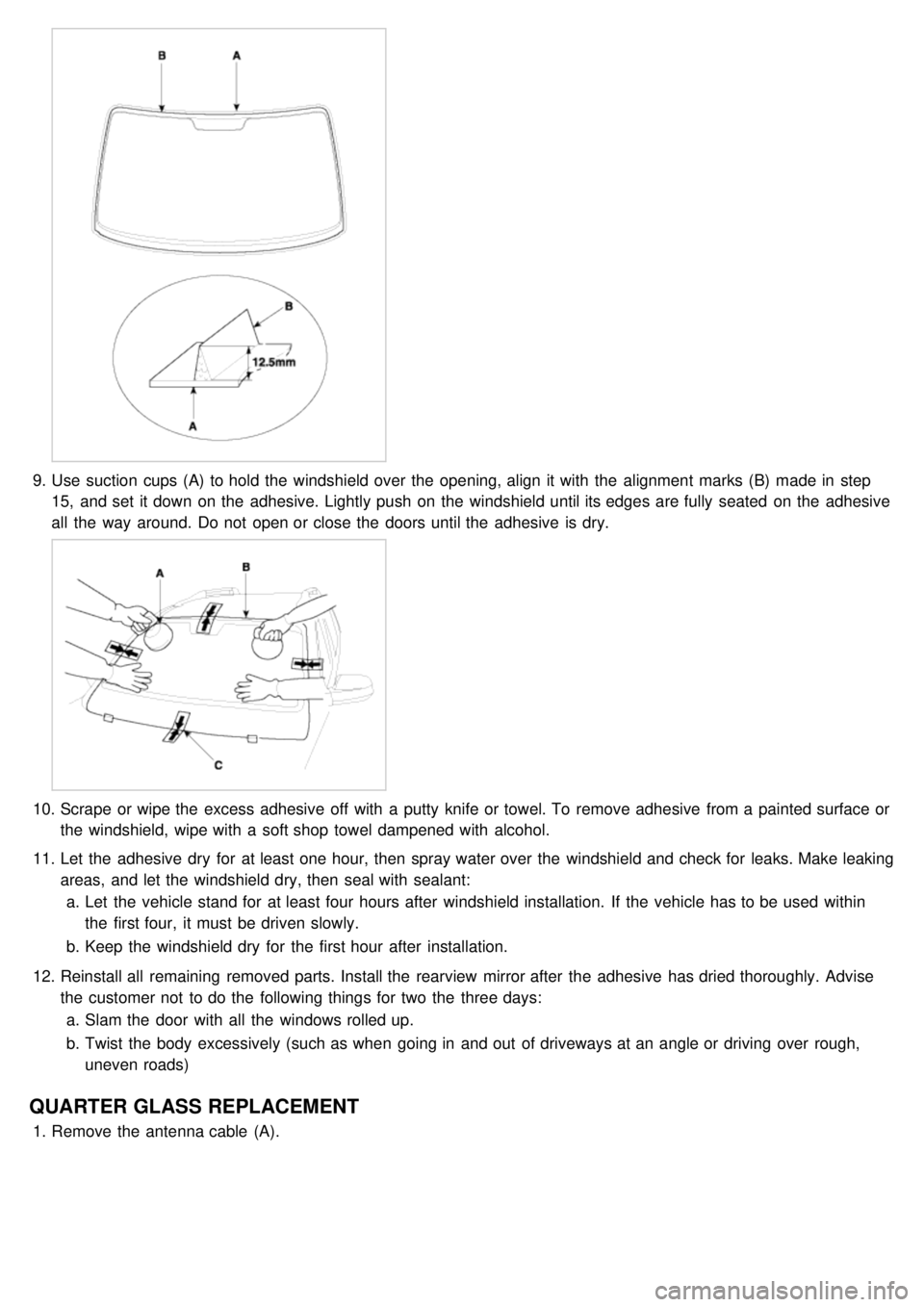
9.Use suction cups (A) to hold the windshield over the opening, align it with the alignment marks (B) made in step
15, and set it down on the adhesive. Lightly push on the windshield until its edges are fully seated on the adhesive
all the way around. Do not open or close the doors until the adhesive is dry.
10. Scrape or wipe the excess adhesive off with a putty knife or towel. To remove adhesive from a painted surface or
the windshield, wipe with a soft shop towel dampened with alcohol.
11. Let the adhesive dry for at least one hour, then spray water over the windshield and check for leaks. Make leaking
areas, and let the windshield dry, then seal with sealant:
a. Let the vehicle stand for at least four hours after windshield installation. If the vehicle has to be used within
the first four, it must be driven slowly.
b. Keep the windshield dry for the first hour after installation.
12. Reinstall all remaining removed parts. Install the rearview mirror after the adhesive has dried thoroughly. Advise
the customer not to do the following things for two the three days:
a. Slam the door with all the windows rolled up.
b. Twist the body excessively (such as when going in and out of driveways at an angle or driving over rough,
uneven roads)
QUARTER GLASS REPLACEMENT
1.Remove the antenna cable (A).
Page 1183 of 1575
2.Touch one tester probe to the glass antenna terminal (A) hear, and move the other tester probe along the antenna
wires to check that continuity exists.
GLASS ANTENNA REPAIR
To make an effective repair, the broken section must be no longer than one inch.
1. Lightly rub the area around the broken section (A) with fine steel wool, and then clean it with alcohol.
2.Carefully mask above and below the broken portion of the glass antenna wire (B) with cellophane tape (C).
3. Using a small brush, apply a heavy coat of silver conductive paint (A) extending about 1/8"on both sides of the
break. Allow 30 minutes to dry.
Thoroughly mix the paint before use.
Page 1194 of 1575
REPLACEMENT
1.Disconnect the negative ( - ) battery terminal.
2. Remove the steering column upper and lower shrouds (A) after removing 3 screws.
3.Disconnect the light switch(A) connector and pin(B).
[LHD]
[RHD]
Page 1209 of 1575
2007 > 2.7L V6 GASOLINE >
INSPECTION
1.Check that the red light flickers when the door lock or unlock button is pressed on the transmitter.
2. Remove the battery and check voltage if the red light doesn't flicker.
Standard voltage : 3V
3.Replace the transmitter battery with a new one, if voltage is below 3V then try to lock and unlock the doors with the
transmitter by pressing the lock or unlock button five or six times.
4. If the doors lock and unlock, the transmitter is O.K, but if the doors don't lock and unlock, register the transmitter
code, then try to lock and unlock the doors.
5. If the transmitter is failure, replace only the transmitter.
Page 1211 of 1575

2007 > 2.7L V6 GASOLINE >
DESCRIPTION
All modules are linked a low speed CAN network.
The input information for the modules is coming from both the CAN network and the hardware components
(actuatorsand sensors).
a. FAM (Front Area Module)
a. Headlamp low/high beam control (with DRL)
b. Park lamp control
c. Front fog lamp control
d. Front turn signal lamp control
e. Windshield wiper control
f. Windshield deicer
g. Diagnostics
b. IPM (In - Panel Module)
a. RKE (Remote Keyless Control)
b. VAS (Voice Alarm System)
c. Ignition key hole illumination
d. Switch indicators control
e. Panel light control
f. Seat belt warning
g. Auto light/DRL control (Logic)
h. Windshield/Rear wiper control (Logic)
i. Turn and Hazard lamp control (Logic)
j. Central door lock (Logic)
k. Windshield deicer timer
l. Rear glass defog timer
m. Gateway for ISO- 9141 (K- Line)
c. RAM (Rear Area Module)
a. Tail lamp control
b. Turn and Hazard lamp control
c. Back up lamp control
d. Rea fog lamp control
e. Stop lamp outage detection
f. Sliding door power window/Quarter glass control
g. Room lamp control
h. Rear wiper control
i. Rear glass defog
j. Fuel filler door open solenoid control
d. ADM (Assist Drive Module)
e. DDM (Driver Drive Module)
MODULE INTRODUCTION
FAM/IPM/RAM consists of a power board and an electronic board. The power board contains circuit protection devices
and switching devices. The electronic board uses Intelligent Power Switching (IPS) for HS/LS load control, logic
functions and CAN/K- Line communication. The power board and electronic board are connected with pin blocks for
the Front Area Module (FAM) and VCD (Variable Connection Displacement) for the In- Panel Module (IPM) and the
Rear Area Module (RAM).
Page 1212 of 1575
Functions
Exterior Lighting Functions
The exterior lighting function has to provide the lighting and signalling of the vehicle; it monitors different available
lights in front or at the back of the vehicle: a. Park and Tail lamps (with Side marker lamps),
b. License plate lamps,
c. Head lamps Low Beam,
d. Head lamps High Beam,
e. Front and Rear fog lamps (with the Rear fog lamp switch indicator),
f. Stop lamps,
g. Backup lamps,
h. Turn signal and side repeater lamps.
Park/tail Lamps Function
1.Necessary conditions to switch ON :
a. By putting the Head lamp switch in position 'Park and Tail lamp' or 'Head lamp Low Beam' or Auto light
activation or DRL activation
2. Necessary conditions to switch OFF :
a. If they are released by the Head lamp switch (Auto light function deactivated) and if DRL function is deactivated
b. If the Auto light function is active but the Auto light Sensor signal status is OFF or Battery Saver function is
active.
3. Functional diagram
Page 1213 of 1575

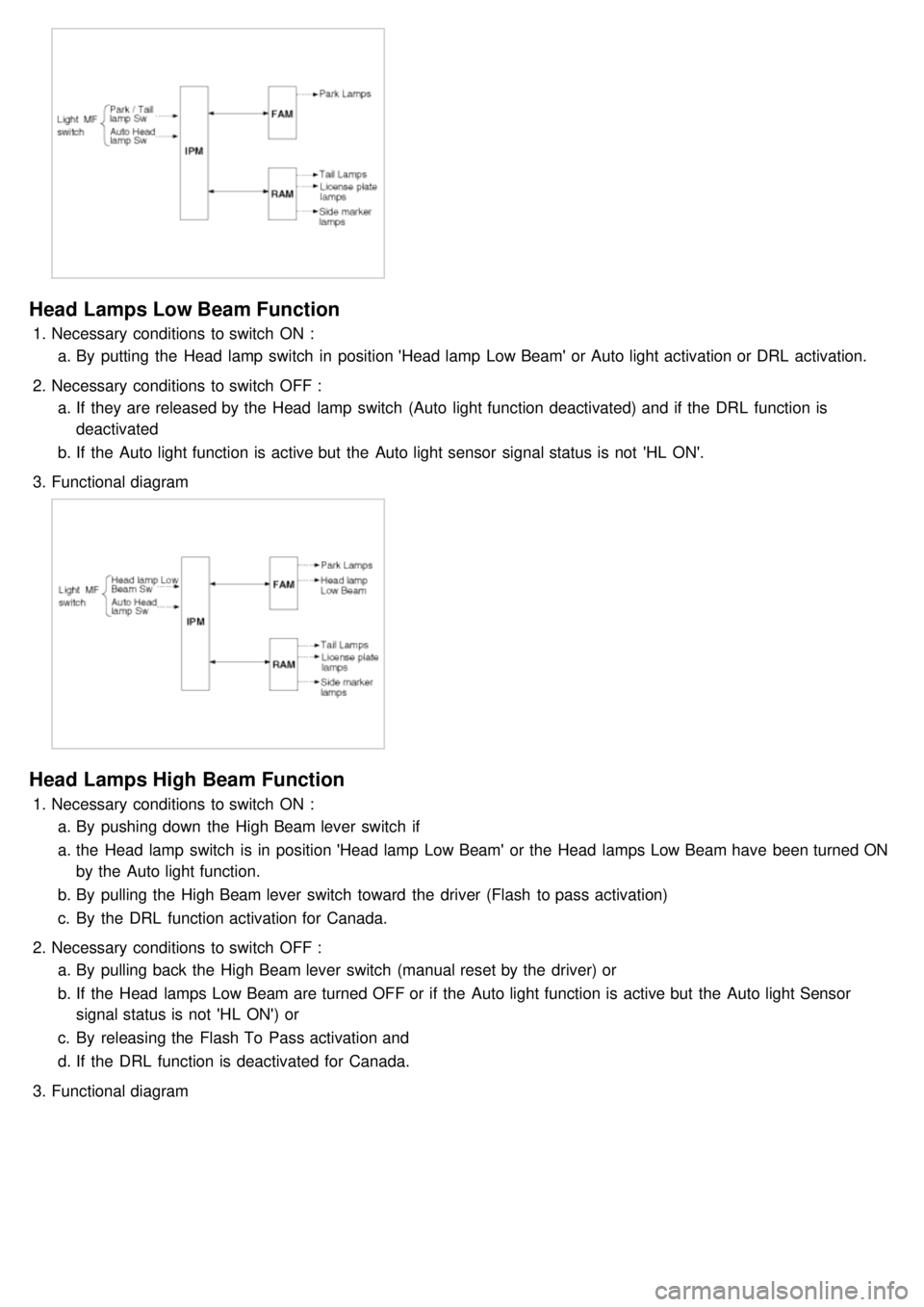
Head Lamps Low Beam Function
1.Necessary conditions to switch ON :
a. By putting the Head lamp switch in position 'Head lamp Low Beam' or Auto light activation or DRL activation.
2. Necessary conditions to switch OFF :
a. If they are released by the Head lamp switch (Auto light function deactivated) and if the DRL function is
deactivated
b. If the Auto light function is active but the Auto light sensor signal status is not 'HL ON'.
3. Functional diagram
Head Lamps High Beam Function
1.Necessary conditions to switch ON :
a. By pushing down the High Beam lever switch if
a. the Head lamp switch is in position 'Head lamp Low Beam' or the Head lamps Low Beam have been turned ON
by the Auto light function.
b. By pulling the High Beam lever switch toward the driver (Flash to pass activation)
c. By the DRL function activation for Canada.
2. Necessary conditions to switch OFF :
a. By pulling back the High Beam lever switch (manual reset by the driver) or
b. If the Head lamps Low Beam are turned OFF or if the Auto light function is active but the Auto light Sensor
signal status is not 'HL ON') or
c. By releasing the Flash To Pass activation and
d. If the DRL function is deactivated for Canada.
3. Functional diagram
Page 1215 of 1575
1.Necessary conditions to switch ON :
a. By using the stalk: Head lamp switch in position 'Head lamp Low Beam' and Front Fog lamp sw ON
b. When Auto light function activated and Auto light Sensor signal status is 'HL ON' and Front Fog lamp sw ON
2. Necessary conditions to switch OFF :
a. When Auto light function activated and Auto light Sensor signal status is not ON
b. When Front fog lamp sw OFF.
3. Functionnal Diagram
Backup Lamps Function
1.Necessary conditions to switch ON :
a. When inhibit sw 'R' read by FAM is active and transmitted to RAM by CAN signal.
2. Necessary conditions to switch OFF :
a. When inhibit sw 'R' read by FAM is not active and transmitted to RAM by CAN signal.
3. Functional diagram