Page 1381 of 6020
ENGINE MECHANICAL (4JK1/4JJ1) 6A-21
Removal
1. Remove the engine hood.
2. Remove the engine cover.
3. Set the hoist and the engine hanger of the special tool (special tool 5-8840-2823-0).
4. Remove the engine mount.
• Before removing the engine mount, hang the engine with a hoist.
• Remove the bolts of the engine mount.
• Hoist the engine assembly slightly to remove the engine mount.
RTW 56ASH004501
Installation
1. Install the engine mount and tighten up with the
specified torque.
Tightening torque: 52 N ⋅
⋅⋅
⋅
m (5.3 kg ⋅
⋅⋅
⋅
m / 38 lb ft)
2. Install the engine cover.
3. Install the engine hood. • Check if nothing is wrong with the engine
mount by starting the engine.
BACK TO CHAPTER INDEX
TO MODEL INDEX
ISUZU KB P190 2007
Page 1383 of 6020
ENGINE MECHANICAL (4JK1/4JJ1) 6A-23
Cylinder Head Cover
Components
RTW 76ALF000101
Legend 1. Oil Filler Cap
2. Oil Filler Cap Gasket
3. Cylinder Head Cover
4. Bolt 5. Head Cover Mounting Rubber
6. Nozzle Seal Cover
7. Head Cover Gasket
8. Nut
BACK TO CHAPTER INDEX
TO MODEL INDEX
ISUZU KB P190 2007
Page 1385 of 6020
ENGINE MECHANICAL (4JK1/4JJ1) 6A-25
8. Remove the cylinder head cover.
LNW 71BSH000401
9. Remove the nozzle seal cover from the cylinder
head cover.
• Remove from the lower side of cylinder head
cover.
10. Remove the cam end gasket (1). • Remove the liquid gasket that has adhered to
cylinder head completely.
RTW 56ASH020501
Installation
1. Install the nozzle seal cover.
• Insert from the lower side of cylinder head
cover.
•
Apply soapy water or engine oil to the surface
of cylinder head cover side.
• Insert the nozzle seal cover as far as it will go.
2. Install the cam end gasket. • Apply the liquid gasket (ThreeBond TB-1207B
or equivalent) and mount.
RTW 56ASH020601
Legend
1. Cam End Gasket
2. Apply The Liquid Gasket
3. 2.0 - 3.0 mm (0.079 - 0.118 in)
• Apply attaching cam end gasket.
Apply the liquid gasket (ThreeBond TB-1207B or equivalent).
BACK TO CHAPTER INDEX
TO MODEL INDEX
ISUZU KB P190 2007
Page 1449 of 6020

ENGINE MECHANICAL (4JK1/4JJ1) 6A-89
Installation
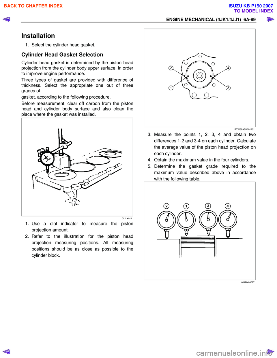
1. Select the cylinder head gasket.
Cylinder Head Gasket Selection
Cylinder head gasket is determined by the piston head
projection from the cylinder body upper surface, in orde
r
to improve engine performance.
Three types of gasket are provided with difference o
f
thickness. Select the appropriate one out of three
grades of
gasket, according to the following procedure.
Before measurement, clear off carbon from the piston
head and cylinder body surface and also clean the
place where the gasket was installed.
011LX011
1. Use a dial indicator to measure the piston
projection amount.
2. Refer to the illustration for the piston head projection measuring positions. All measuring
positions should be as close as possible to the
cylinder block.
RTW 36ASH001701
3. Measure the points 1, 2, 3, 4 and obtain two
differences 1-2 and 3-4 on each cylinder. Calculate
the average value of the piston head projection on
each cylinder.
4. Obtain the maximum value in the four cylinders.
5. Determine the gasket grade required to the maximum value described above in accordance
with the following table.
011RY00027
BACK TO CHAPTER INDEX
TO MODEL INDEX
ISUZU KB P190 2007
Page 1461 of 6020
ENGINE MECHANICAL (4JK1/4JJ1) 6A-101
Piston and Connecting Rod
Components
RTW A56ALF001601
Legend 1. Piston Pin Snap Ring
2. Piston Pin
3. Piston Ring 4. Piston
5. Connecting Rod
6. Bearing
Removal
1. Demount the engine assembly.
Refer to “Engine Assembly”.
2. Remove the cylinder head cover.
Refer to “Cylinder Head Cover”.
3. Remove the camshaft assembly.
Refer to “Camshaft Assembly”.
4. Remove the cylinder head.
Refer to “Cylinder Head”.
5. Remove the gear case assembly.
Refer to “Gear Case Assembly”.
6. Remove the oil pan.
Refer to “Oil Pan” .
7. Remove the connecting rod cap.
BACK TO CHAPTER INDEX
TO MODEL INDEX
ISUZU KB P190 2007
Page 1480 of 6020
6A-120 ENGINE MECHANICAL (4JK1/4JJ1)
Crankshaft Front Oil Seal
Components
RTW 76AMF000501
Legend 1. Bolt
2. W asher 3. Crankshaft Damper Pulley
4. Crankshaft Front Oil Seal
Removal
1. Remove the fan assembly.
• Remove the fan assembly unscrewing fou
r
mounting nuts.
RTW 56ASH025401
2. Remove the fan belt.
BACK TO CHAPTER INDEX
TO MODEL INDEX
ISUZU KB P190 2007
Page 1487 of 6020

ENGINE MECHANICAL (4JK1/4JJ1) 6A-127
Removal
1. Demount the engine assembly.
Refer to "Engine Assembly".
2. Remove the cylinder head cover.
Refer to "Cylinder Head Cover".
3. Remove the camshaft.
Refer to "Camshaft Assembly".
4. Remove the cylinder head.
Refer to "Cylinder Head".
5. Remove the fuel supply pump and fuel rail.
Refer to "Fuel Supply Pump" and "Fuel Rail" in the fuel system section.
6. Remove the front cover.
Refer to "Front Cover".
7. Remove the crankshaft rear oil seal.
Refer to "Crankshaft Rear Oil Seal".
8. Remove the water pump.
Refer to "W ater Pump" in Cooling System Section.
9. Remove the timing gear train.
Refer to "Timing Gear Train".
10.Remove the oil pump.
Refer to "Oil Pump".
11. Remove the gear case assembly.
Refer to “Gear Case Assembly”.
12. Remove the crankshaft gear.
901R100008
13. Remove the crank case.
Refer to "Crank Case and Oil Pan".
14.Remove pistons and connecting rods.
Refer to "Piston and Connecting Rod".
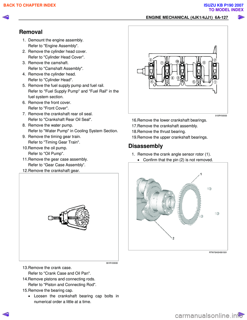
15. Remove the bearing cap. • Loosen the crankshaft bearing cap bolts in
numerical order a little at a time.
015RY00003
16.Remove the lower crankshaft bearings.
17.Remove the crankshaft assembly.
18.Remove the thrust bearing.
19.Remove the upper crankshaft bearings.
Disassembly
1. Remove the crank angle sensor rotor (1). • Confirm that the pin (2) is not removed.
RTW 76ASH001501
BACK TO CHAPTER INDEX
TO MODEL INDEX
ISUZU KB P190 2007
Page 1488 of 6020

6A-128 ENGINE MECHANICAL (4JK1/4JJ1)
Reassembly
1. Install the crank angle sensor rotor.
• Attach by making a rotor tooth’s running out
side into a front side.
•
Apply Loctite #262 or the equivalent to the bolt
threads (if a new bolt is used, Loctite
application is not required).
Tightening torque: 12 N ⋅
⋅⋅
⋅
m (1.2 kg ⋅
⋅⋅
⋅
m / 104 lb in)
RTW 76ASH001601
Legend
1. Crank Angle Sensor Rotor
2. Pin
Inspection
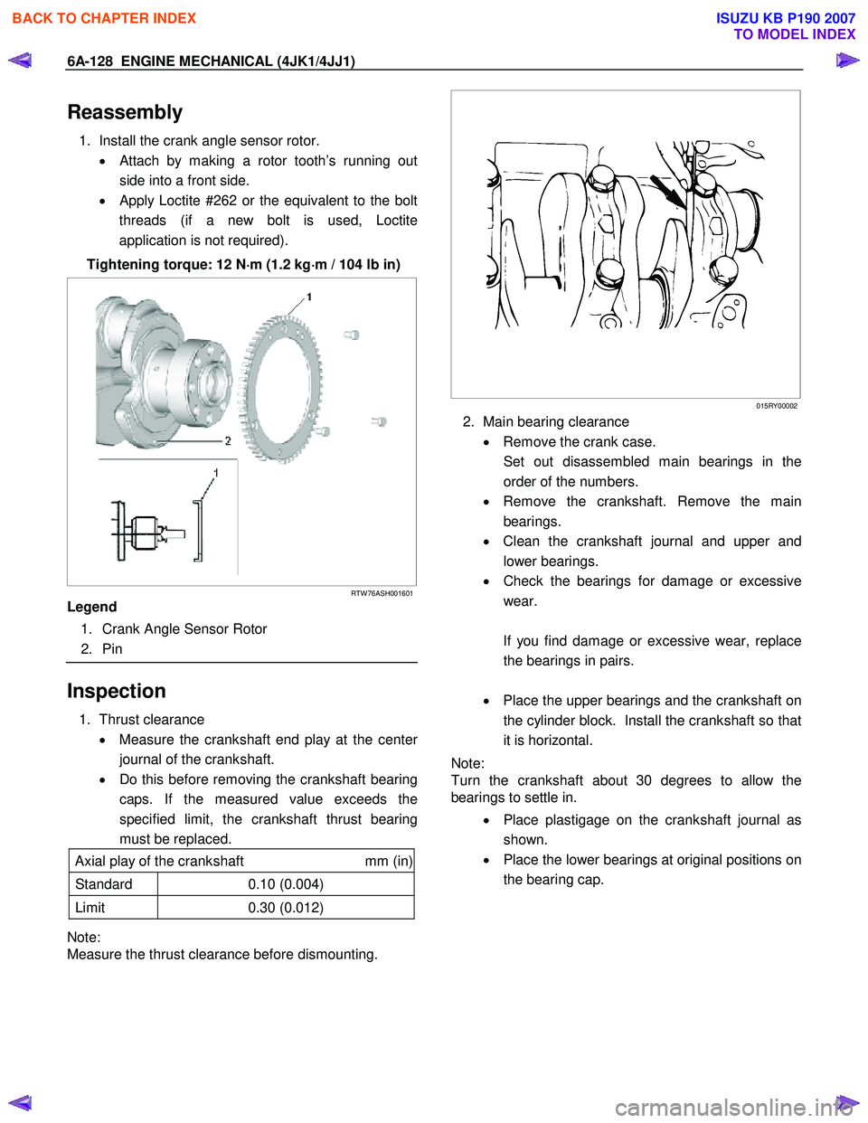
1. Thrust clearance
• Measure the crankshaft end play at the cente
r
journal of the crankshaft.
• Do this before removing the crankshaft bearing
caps. If the measured value exceeds the
specified limit, the crankshaft thrust bearing
must be replaced.
Axial play of the crankshaft mm (in)
Standard 0.10 (0.004)
Limit 0.30 (0.012)
Note:
Measure the thrust clearance before dismounting.
015RY00002
2. Main bearing clearance
• Remove the crank case.
Set out disassembled main bearings in the order of the numbers.
• Remove the crankshaft. Remove the main
bearings.
• Clean the crankshaft journal and upper and
lower bearings.
• Check the bearings for damage or excessive
wear.
If you find damage or excessive wear, replace the bearings in pairs.
• Place the upper bearings and the crankshaft on
the cylinder block. Install the crankshaft so that
it is horizontal.
Note:
Turn the crankshaft about 30 degrees to allow the
bearings to settle in.
• Place plastigage on the crankshaft journal as
shown.
• Place the lower bearings at original positions on
the bearing cap.
BACK TO CHAPTER INDEX
TO MODEL INDEX
ISUZU KB P190 2007