Page 1494 of 6020
6A-134 ENGINE MECHANICAL (4JK1/4JJ1)
7. Install the crank case.
Refer to "Crank Case and Oil Pan".
8. Install the crankshaft gear.
RTW 56ASH017001
9. Install the gear case assembly.
Refer to "Gear Case Assembly".
10.Install the oil pump.
Refer to "Oil Pump".
11.Install the timing gear train.
Refer to "Timing Gear Train".
12.Install the water pump.
Refer to "W ater Pump" in Cooling System Section.
13.Install the front cover.
Refer to "Timing Gear Train".
14.Install the crankshaft rear oil seal.
Refer to "Crankshaft Rear Oil Seal".
15.Install the fuel supply pump and fuel rail.
Refer to "Fuel Supply Pump" and "Fuel Rail".
16.Install the cylinder head.
Refer to "Cylinder Head".
17.Install the camshaft assembly.
Refer to "Camshaft Assembly".
18.Install the cylinder head cover.
Refer to "Cylinder Head Cover".
19.Mount the engine assembly on the chassis.
Refer to "Engine Assembly".
BACK TO CHAPTER INDEX
TO MODEL INDEX
ISUZU KB P190 2007
Page 1496 of 6020

6A-136 ENGINE MECHANICAL (4JK1/4JJ1)
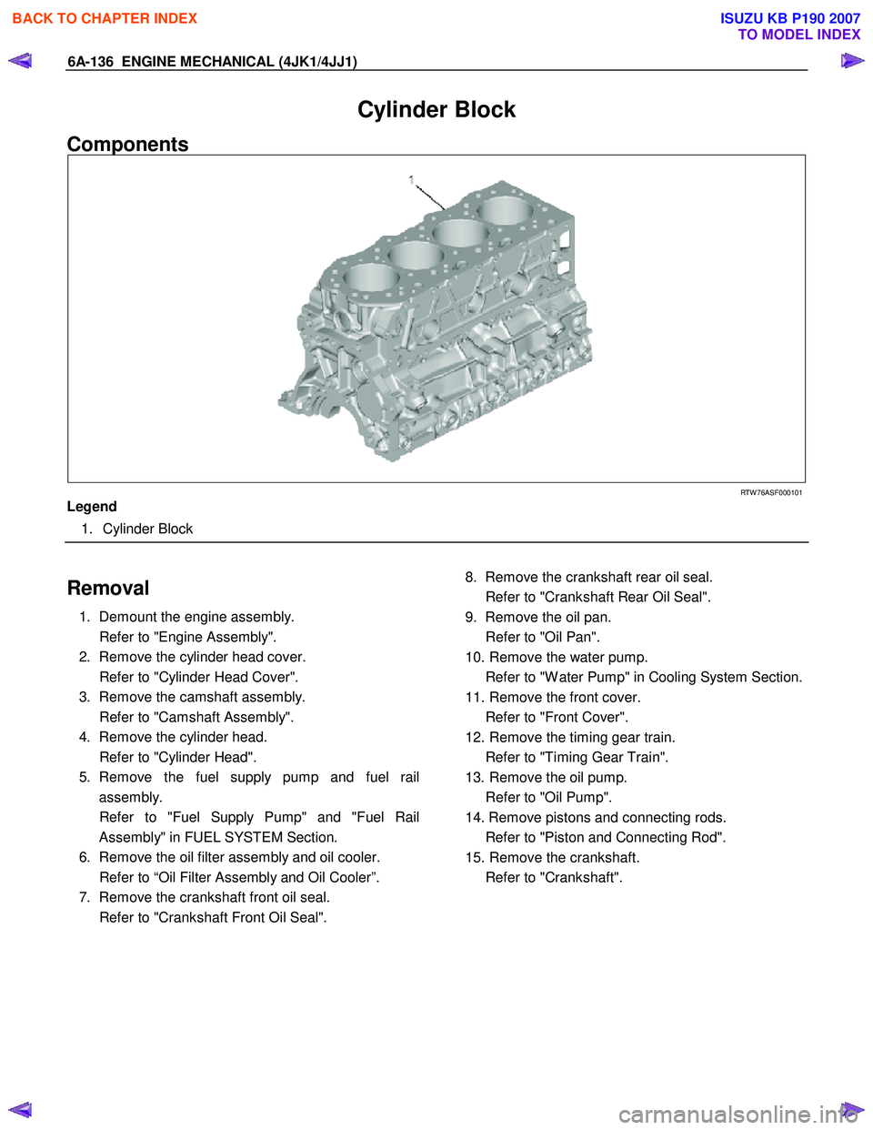
Cylinder Block
Components
RTW 76ASF000101
Legend
1. Cylinder Block
Removal
1. Demount the engine assembly.
Refer to "Engine Assembly".
2. Remove the cylinder head cover.
Refer to "Cylinder Head Cover".
3. Remove the camshaft assembly.
Refer to "Camshaft Assembly".
4. Remove the cylinder head.
Refer to "Cylinder Head".
5. Remove the fuel supply pump and fuel rail assembly.
Refer to "Fuel Supply Pump" and "Fuel Rail Assembly" in FUEL SYSTEM Section.
6. Remove the oil filter assembly and oil cooler.
Refer to “Oil Filter Assembly and Oil Cooler”.
7. Remove the crankshaft front oil seal.
Refer to "Crankshaft Front Oil Seal".
8. Remove the crankshaft rear oil seal.
Refer to "Crankshaft Rear Oil Seal".
9. Remove the oil pan.
Refer to "Oil Pan".
10. Remove the water pump.
Refer to "W ater Pump" in Cooling System Section.
11. Remove the front cover.
Refer to "Front Cover".
12. Remove the timing gear train.
Refer to "Timing Gear Train".
13. Remove the oil pump.
Refer to "Oil Pump".
14. Remove pistons and connecting rods.
Refer to "Piston and Connecting Rod".
15. Remove the crankshaft.
Refer to "Crankshaft".
BACK TO CHAPTER INDEX
TO MODEL INDEX
ISUZU KB P190 2007
Page 1497 of 6020

ENGINE MECHANICAL (4JK1/4JJ1) 6A-137
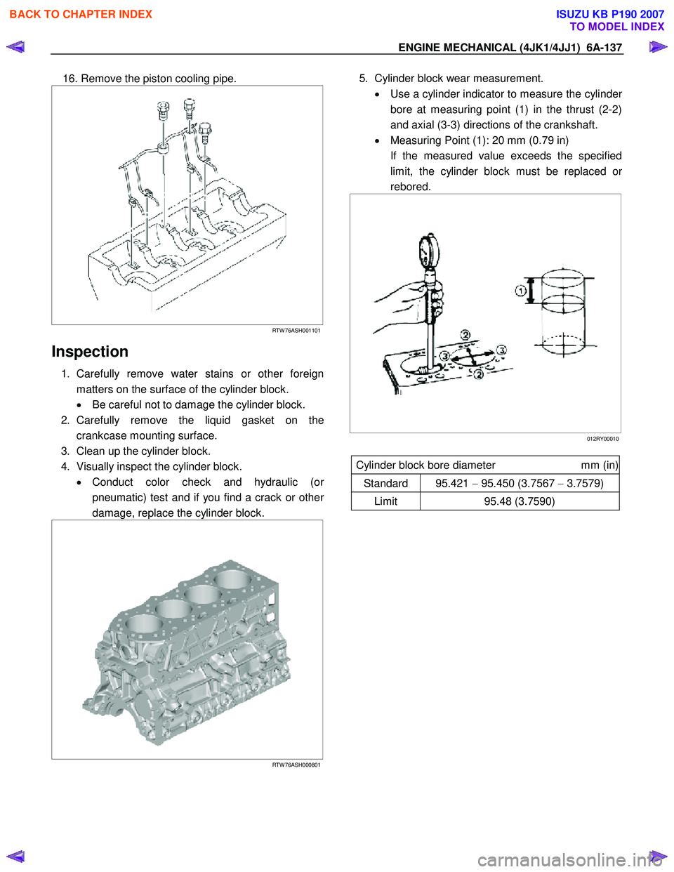
16. Remove the piston cooling pipe.
RTW 76ASH001101
Inspection
1. Carefully remove water stains or other foreign
matters on the surface of the cylinder block.
• Be careful not to damage the cylinder block.
2. Carefully remove the liquid gasket on the crankcase mounting surface.
3. Clean up the cylinder block.
4. Visually inspect the cylinder block. • Conduct color check and hydraulic (o
r
pneumatic) test and if you find a crack or other
damage, replace the cylinder block.
RTW 76ASH000801
5. Cylinder block wear measurement.
• Use a cylinder indicator to measure the cylinde
r
bore at measuring point (1) in the thrust (2-2)
and axial (3-3) directions of the crankshaft.
• Measuring Point (1): 20 mm (0.79 in)
If the measured value exceeds the specified limit, the cylinder block must be replaced o
r
rebored.
012RY00010
Cylinder block bore diameter mm (in)
Standard 95.421 − 95.450 (3.7567 − 3.7579)
Limit 95.48 (3.7590)
BACK TO CHAPTER INDEX
TO MODEL INDEX
ISUZU KB P190 2007
Page 1499 of 6020

ENGINE MECHANICAL (4JK1/4JJ1) 6A-139
Cylinder block height (H) (Reference) mm (in)
Standard 259.945 – 260.055 (10.2340 – 10.2384)
012R100009
Installation
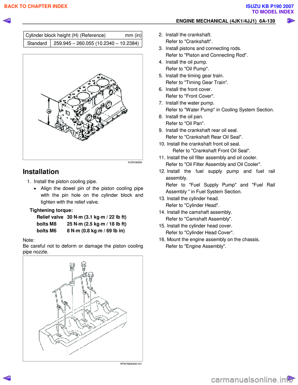
1. Install the piston cooling pipe.
• Align the dowel pin of the piston cooling pipe
with the pin hole on the cylinder block and
tighten with the relief valve.
Tightening torque: Relief valve 30 N ⋅
⋅⋅
⋅
m (3.1 kg ⋅
⋅⋅
⋅
m / 22 lb ft)
bolts M8 25 N ⋅
⋅⋅
⋅
m (2.5 kg ⋅
⋅⋅
⋅
m / 18 lb ft)
bolts M6 8 N ⋅
⋅⋅
⋅
m (0.8 kg ⋅
⋅⋅
⋅
m / 69 lb in)
Note:
Be careful not to deform or damage the piston cooling
pipe nozzle.
RTW 76ASH001101
2. Install the crankshaft.
Refer to "Crankshaft".
3. Install pistons and connecting rods.
Refer to "Piston and Connecting Rod".
4. Install the oil pump.
Refer to "Oil Pump".
5. Install the timing gear train.
Refer to "Timing Gear Train".
6. Install the front cover.
Refer to "Front Cover".
7. Install the water pump.
Refer to "W ater Pump" in Cooling System Section.
8. Install the oil pan.
Refer to "Oil Pan".
9. Install the crankshaft rear oil seal.
Refer to "Crankshaft Rear Oil Seal".
10. Install the crankshaft front oil seal. Refer to "Crankshaft Front Oil Seal".
11. Install the oil filter assembly and oil cooler.
Refer to "Oil Filter Assembly and Oil Cooler".
12. Install the fuel supply pump and fuel rail assembly.
Refer to "Fuel Supply Pump" and "Fuel Rail Assembly " in Fuel System Section.
13. Install the cylinder head.
Refer to "Cylinder Head".
14. Install the camshaft assembly.
Refer to "Camshaft Assembly".
15. Install the cylinder head cover.
Refer to "Cylinder Head Cover".
16. Mount the engine assembly on the chassis.
Refer to "Engine Assembly".
BACK TO CHAPTER INDEX
TO MODEL INDEX
ISUZU KB P190 2007
Page 1506 of 6020
6A-146 ENGINE MECHANICAL (4JK1/4JJ1)
6. Remove the water intake pipe.
RTW 56ASH012601
Legend
1. W ater Intake Pipe
2. Bracket
3. Bracket
4. Bolt
7. Remove the oil cooler.
RTW 66ASH009101
Disassembly
1. Remove the element mounting nut (1).
RTW 56ASH012901
2. Remove the element (1).
3. Remove the gasket (2).
RTW 56ASH013001
BACK TO CHAPTER INDEX
TO MODEL INDEX
ISUZU KB P190 2007
Page 1507 of 6020
ENGINE MECHANICAL (4JK1/4JJ1) 6A-147
Reassembly
1. Install the gasket on the element.
2. Install the element.
3. Tighten the element fixing nut using the specified torque.
Tightening torque: 25 N ⋅
⋅⋅
⋅
m (2.5 kg ⋅
⋅⋅
⋅
m / 18 lb ft)
Installation
1. Install the oil filter and cooler.
• Install the O-ring on the oil filter and cooler,
apply grease.
•
Apply the liquid gasket and mount within 5
minutes. Apply liquid gasket (ThreeBond TB-
1207C or equivalent) to the flange surface
groove (cylinder block). Bead diameter must
be between 2 and 3 mm (0.079 and 0.118 in).
Refer to the illustration for the offset position
(no more than 1 mm (0.004 in)).
RTW 56ASH013101
Legend
1. Liquid Gasket
2. O-ring
• Align the oil filter and cooler holes with the
cylinder block studs. Install the oil cooler to the
cylinder clock.
BACK TO CHAPTER INDEX
TO MODEL INDEX
ISUZU KB P190 2007
Page 1513 of 6020

ENGINE MECHANICAL (4JK1/4JJ1) 6A-153
Installation
1. Install the crank case.
• Apply the liquid gasket (ThreeBond TB-1207C
or equivalent) and mount within 5 minutes.
Tightening torque: 25 N ⋅
⋅⋅
⋅
m (2.5 kg ⋅
⋅⋅
⋅
m / 18 lb ft)
RTW 56ASH015301
Legend
1. 2.0 - 3.0 mm (0.079 - 0.118 in)
2. 4.0 - 5.0 mm (0.157 - 0.197 in)
2. Install the oil pan.
• Apply the liquid gasket (ThreeBond TB-1207B
or equivalent)and mount within 5 minutes.
Tightening torque: 22 N ⋅
⋅⋅
⋅
m (2.2 kg ⋅
⋅⋅
⋅
m / 16 lb ft)
RTW 56ASH015201
Legend
1. 2.0 mm (0.079 in)
2. 3.0 mm (0.118 in)
3. Install the retainer.
• Apply the liquid gasket (ThreeBond TB-1207C
or equivalent) and mount within 5 minutes.
Tightening torque: 25 N ⋅
⋅⋅
⋅
m (2.5 kg ⋅
⋅⋅
⋅
m / 18 lb ft)
RTW 56ASH017701
Legend
1. 2 - 2.5 mm (0.079 - 0.098 in)
2. 2 - 2.5 mm (0.079 - 0.098 in)
RTW 76ASH002001
Legend
1. Retainer
2. Bolt
4. Install the timing gear case.
Refer to “Gear Case Assembly”.
5. Install the cylinder head.
Refer to “Cylinder Head”.
BACK TO CHAPTER INDEX
TO MODEL INDEX
ISUZU KB P190 2007
Page 1519 of 6020
ENGINE MECHANICAL (4JK1/4JJ1) 6A-159
RTW 56ASH025501
• Measure the Depth size of the gear case
housing surface and the oil pump housing gea
r
case side.
Depth size the gear case housing surface and the oil
pump housing gear case side
mm (in)
Standard 14.500 - 14.527 (0.5709 - 0.5719)
RTW 56ASH014801
Clearance between the gear side surface and the
gear side surface of the oil pump housing mm (in)
Standard 0.063 - 0.027 (0.0025 - 0.0011)
Limit 0.20 (0.0079)
Installation
1. Install the oil pump.
•
Apply engine oil to the oil pump attachment
gearbox.
• Tighten the bolts to the specified torque.
Tightening torque: 25 N ⋅
⋅⋅
⋅
m (2.5 kg ⋅
⋅⋅
⋅
m / 18 lb ft)
• Installed pump gear should be smooth to
rotate.
2. Install the gear case cover. • Apply the liquid gasket (Threebond TB-1207B
or equivalent) mount within 5 minutes.
RTW 56ASH020101
Legend
1. Apply the liquid gasket in area
BACK TO CHAPTER INDEX
TO MODEL INDEX
ISUZU KB P190 2007