2007 ISUZU KB P190 engine mount
[x] Cancel search: engine mountPage 1526 of 6020
ENGINE COOLING (4JK1/4JJ1) 6B-3
General Description
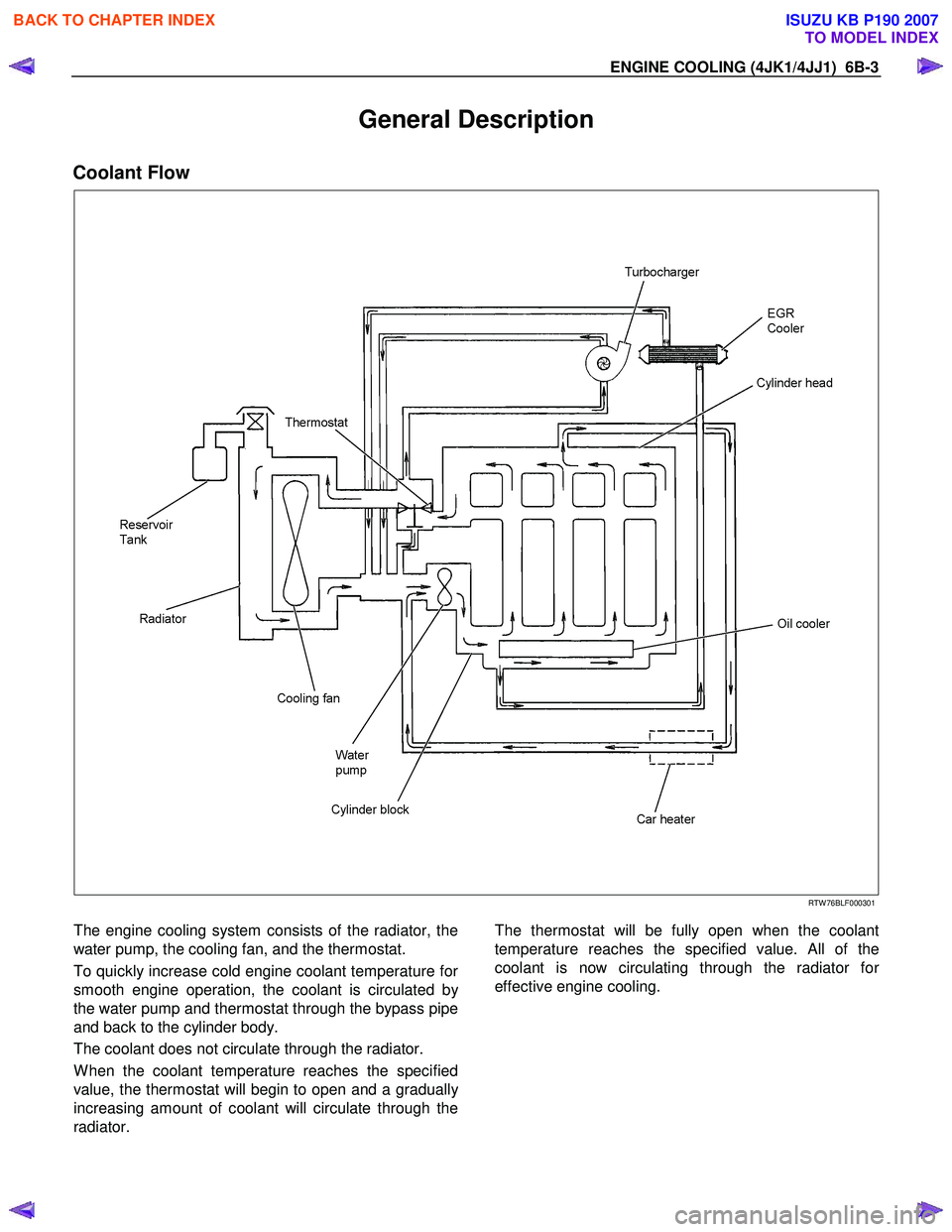
Coolant Flow
RTW 76BLF000301
The engine cooling system consists of the radiator, the
water pump, the cooling fan, and the thermostat.
To quickly increase cold engine coolant temperature fo
r
smooth engine operation, the coolant is circulated by
the water pump and thermostat through the bypass pipe
and back to the cylinder body.
The coolant does not circulate through the radiator.
W hen the coolant temperature reaches the specified
value, the thermostat will begin to open and a graduall
y
increasing amount of coolant will circulate through the
radiator.
The thermostat will be fully open when the coolant
temperature reaches the specified value. All of the
coolant is now circulating through the radiator fo
r
effective engine cooling.
BACK TO CHAPTER INDEX
TO MODEL INDEX
ISUZU KB P190 2007
Page 1535 of 6020
6B-12 ENGINE COOLING (4JK1/4JJ1)
MFW 41CSH001401
Legend
1. W ooden Piece
2. Agitating Rod
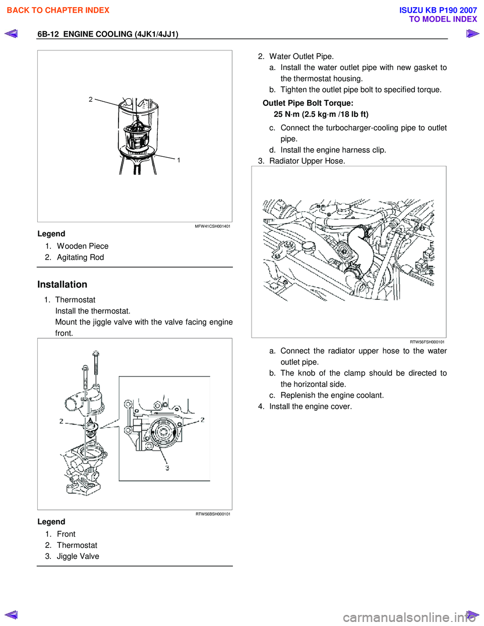
Installation
1. Thermostat
Install the thermostat.
Mount the jiggle valve with the valve facing engine front.
RTW 56BSH000101
Legend
1. Front
2. Thermostat
3. Jiggle Valve
2. W ater Outlet Pipe.
a. Install the water outlet pipe with new gasket to the thermostat housing.
b. Tighten the outlet pipe bolt to specified torque.
Outlet Pipe Bolt Torque: 25 N·m (2.5 kg·m /18 lb ft)
c. Connect the turbocharger-cooling pipe to outlet pipe.
d. Install the engine harness clip.
3. Radiator Upper Hose.
RTW 56FSH000101
a. Connect the radiator upper hose to the water
outlet pipe.
b. The knob of the clamp should be directed to the horizontal side.
c. Replenish the engine coolant.
4. Install the engine cover.
BACK TO CHAPTER INDEX
TO MODEL INDEX
ISUZU KB P190 2007
Page 1547 of 6020
6C-6 FUEL SYSTEM (4JK1/4JJ1)
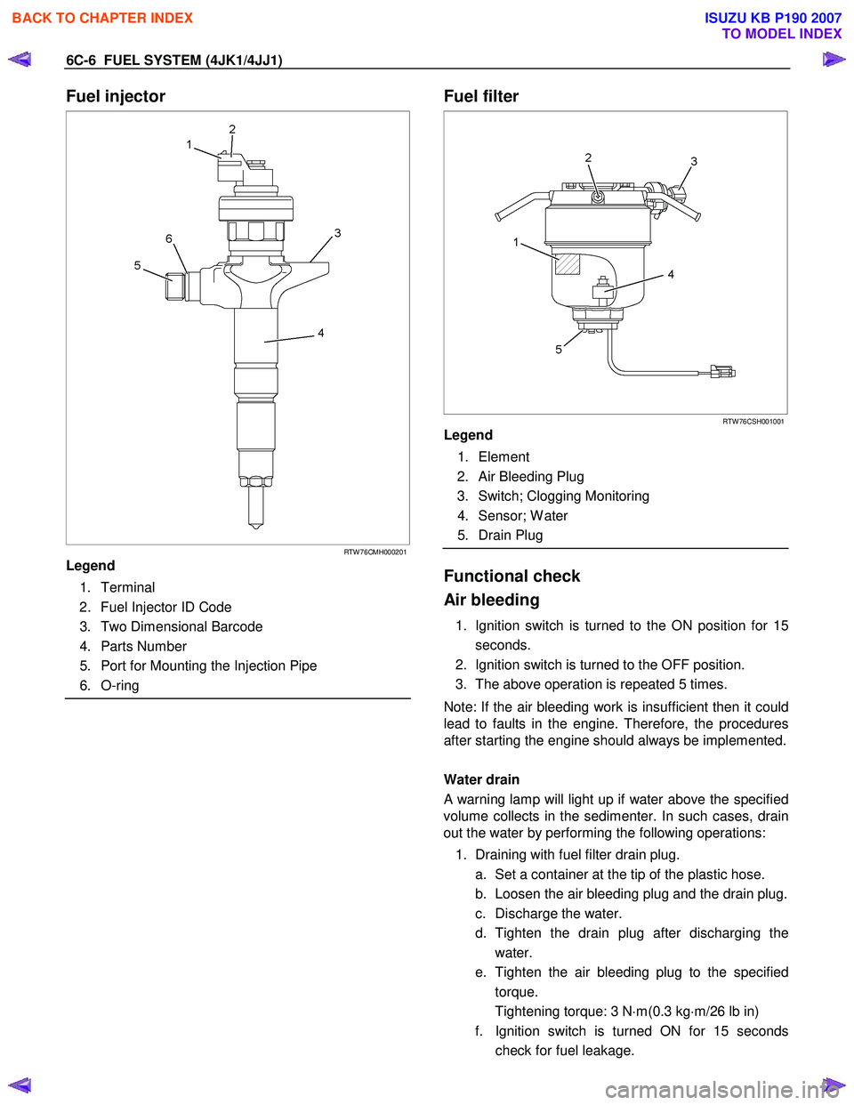
Fuel injector
RTW 76CMH000201
Legend
1. Terminal
2. Fuel Injector ID Code
3. Two Dimensional Barcode
4. Parts Number
5. Port for Mounting the Injection Pipe
6. O-ring
Fuel filter
RTW 76CSH001001
Legend
1. Element
2. Air Bleeding Plug
3. Switch; Clogging Monitoring
4. Sensor; W ater
5. Drain Plug
Functional check
Air bleeding
1. Ignition switch is turned to the ON position for 15 seconds.
2. Ignition switch is turned to the OFF position.
3. The above operation is repeated 5 times.
Note: If the air bleeding work is insufficient then it could
lead to faults in the engine. Therefore, the procedures
after starting the engine should always be implemented.
Water drain
A warning lamp will light up if water above the specified
volume collects in the sedimenter. In such cases, drain
out the water by performing the following operations:
1. Draining with fuel filter drain plug. a. Set a container at the tip of the plastic hose.
b. Loosen the air bleeding plug and the drain plug.
c. Discharge the water.
d. Tighten the drain plug after discharging the water.
e. Tighten the air bleeding plug to the specified torque.
Tightening torque: 3 N ⋅m(0.3 kg ⋅m/26 lb in)
f. Ignition switch is turned ON for 15 seconds check for fuel leakage.
BACK TO CHAPTER INDEX
TO MODEL INDEX
ISUZU KB P190 2007
Page 1566 of 6020
FUEL SYSTEM (4JK1/4JJ1) 6C-25
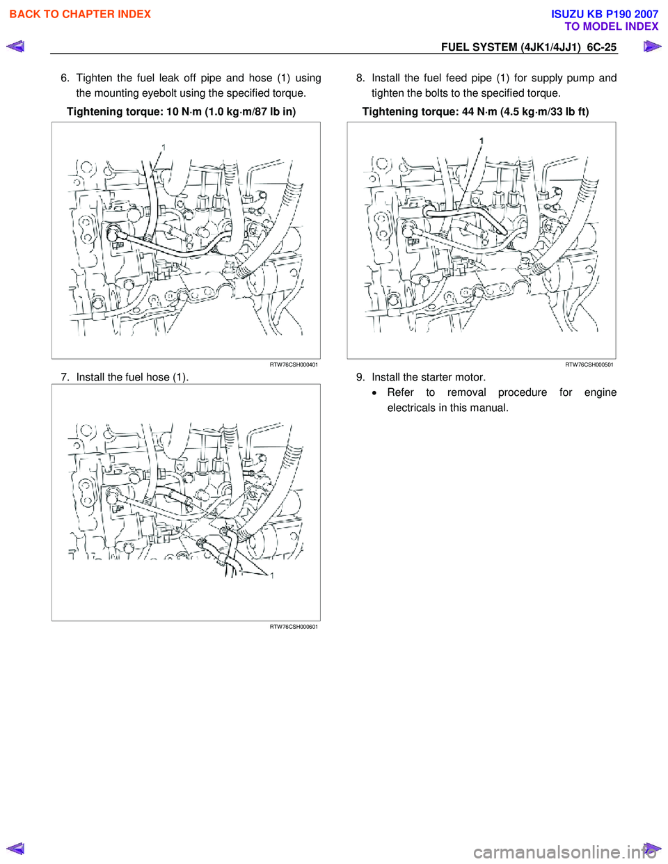
6. Tighten the fuel leak off pipe and hose (1) using
the mounting eyebolt using the specified torque.
Tightening torque: 10 N ⋅
⋅⋅
⋅
m (1.0 kg ⋅
⋅⋅
⋅
m/87 lb in)
RTW 76CSH000401
7. Install the fuel hose (1).
RTW 76CSH000601
8. Install the fuel feed pipe (1) for supply pump and
tighten the bolts to the specified torque.
Tightening torque: 44 N ⋅
⋅⋅
⋅
m (4.5 kg ⋅
⋅⋅
⋅
m/33 lb ft)
RTW 76CSH000501
9. Install the starter motor. • Refer to removal procedure for engine
electricals in this manual.
BACK TO CHAPTER INDEX
TO MODEL INDEX
ISUZU KB P190 2007
Page 1680 of 6020
ENGINE CONTROL SYSTEM (4JK1/4JJ1) 6E-63
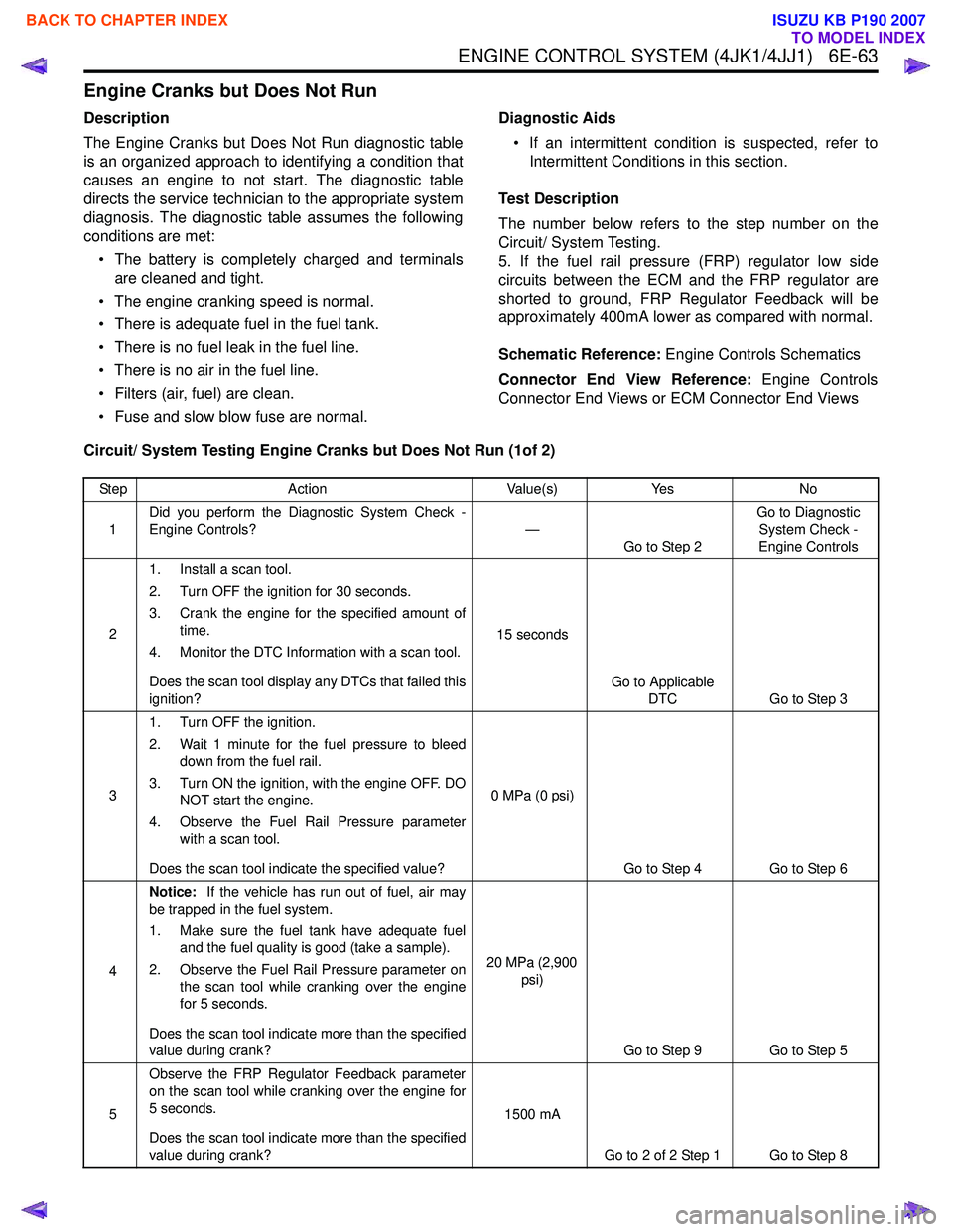
Engine Cranks but Does Not Run
Description
The Engine Cranks but Does Not Run diagnostic table
is an organized approach to identifying a condition that
causes an engine to not start. The diagnostic table
directs the service technician to the appropriate system
diagnosis. The diagnostic table assumes the following
conditions are met:
• The battery is completely charged and terminals are cleaned and tight.
• The engine cranking speed is normal.
• There is adequate fuel in the fuel tank.
• There is no fuel leak in the fuel line.
• There is no air in the fuel line.
• Filters (air, fuel) are clean.
• Fuse and slow blow fuse are normal. Diagnostic Aids
• If an intermittent condition is suspected, refer to Intermittent Conditions in this section.
Test Description
The number below refers to the step number on the
Circuit/ System Testing.
5. If the fuel rail pressure (FRP) regulator low side
circuits between the ECM and the FRP regulator are
shorted to ground, FRP Regulator Feedback will be
approximately 400mA lower as compared with normal.
Schematic Reference: Engine Controls Schematics
Connector End View Reference: Engine Controls
Connector End Views or ECM Connector End Views
Circuit/ System Testing Engine Cranks but Does Not Run (1of 2)
Step Action Value(s)Yes No
1 Did you perform the Diagnostic System Check -
Engine Controls? —
Go to Step 2 Go to Diagnostic
System Check -
Engine Controls
2 1. Install a scan tool.
2. Turn OFF the ignition for 30 seconds.
3. Crank the engine for the specified amount of time.
4. Monitor the DTC Information with a scan tool.
Does the scan tool display any DTCs that failed this
ignition? 15 seconds
Go to Applicable DTC Go to Step 3
3 1. Turn OFF the ignition.
2. Wait 1 minute for the fuel pressure to bleed down from the fuel rail.
3. Turn ON the ignition, with the engine OFF. DO NOT start the engine.
4. Observe the Fuel Rail Pressure parameter with a scan tool.
Does the scan tool indicate the specified value? 0 MPa (0 psi)
Go to Step 4 Go to Step 6
4 Notice:
If the vehicle has run out of fuel, air may
be trapped in the fuel system.
1. Make sure the fuel tank have adequate fuel and the fuel quality is good (take a sample).
2. Observe the Fuel Rail Pressure parameter on the scan tool while cranking over the engine
for 5 seconds.
Does the scan tool indicate more than the specified
value during crank? 20 MPa (2,900
psi)
Go to Step 9 Go to Step 5
5 Observe the FRP Regulator Feedback parameter
on the scan tool while cranking over the engine for
5 seconds.
Does the scan tool indicate more than the specified
value during crank? 1500 mA
Go to 2 of 2 Step 1 Go to Step 8
BACK TO CHAPTER INDEX
TO MODEL INDEX
ISUZU KB P190 2007
Page 1683 of 6020
6E-66 ENGINE CONTROL SYSTEM (4JK1/4JJ1)
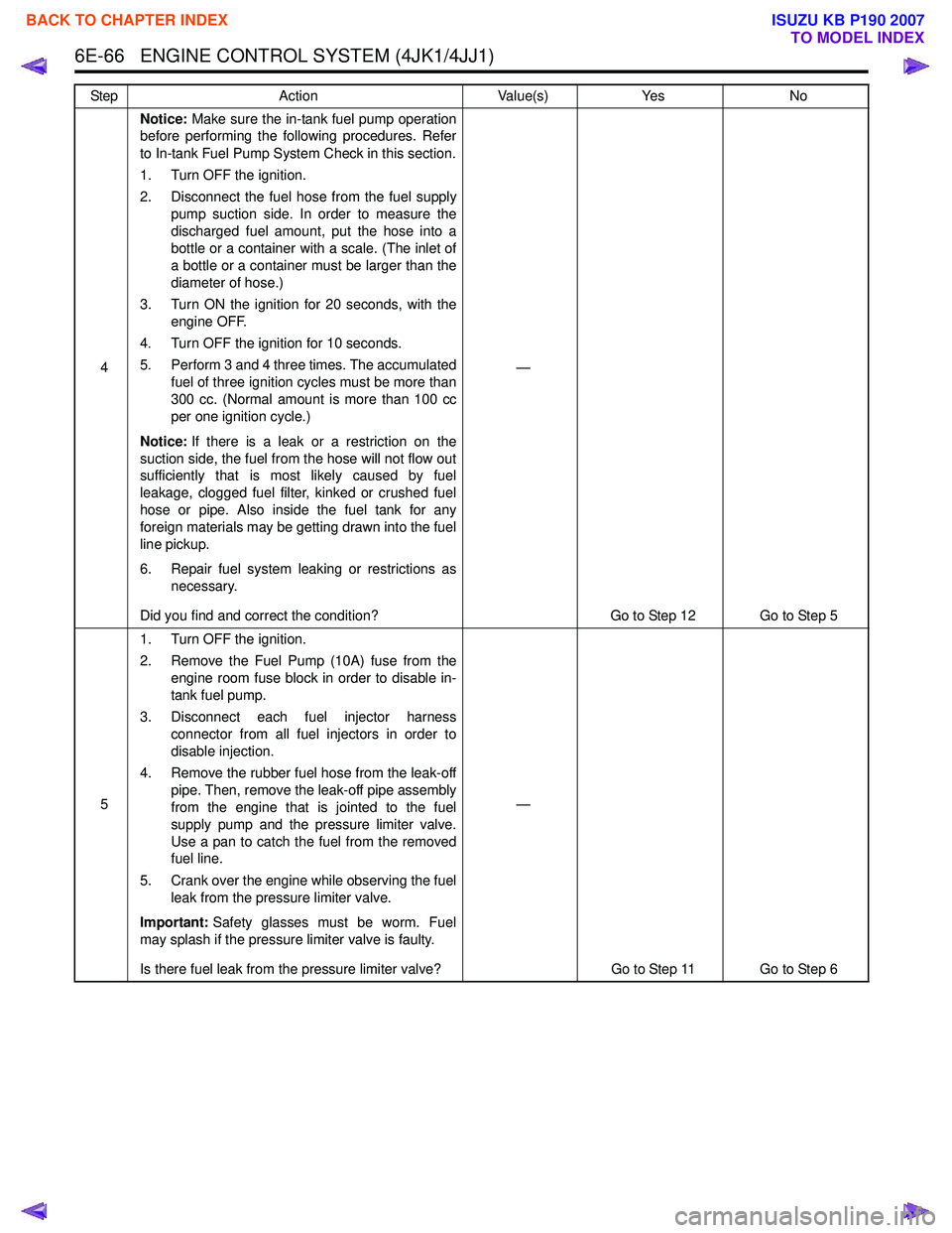
4Notice:
Make sure the in-tank fuel pump operation
before performing the following procedures. Refer
to In-tank Fuel Pump System Check in this section.
1. Turn OFF the ignition.
2. Disconnect the fuel hose from the fuel supply pump suction side. In order to measure the
discharged fuel amount, put the hose into a
bottle or a container with a scale. (The inlet of
a bottle or a container must be larger than the
diameter of hose.)
3. Turn ON the ignition for 20 seconds, with the engine OFF.
4. Turn OFF the ignition for 10 seconds.
5. Perform 3 and 4 three times. The accumulated fuel of three ignition cycles must be more than
300 cc. (Normal amount is more than 100 cc
per one ignition cycle.)
Notice: If there is a leak or a restriction on the
suction side, the fuel from the hose will not flow out
sufficiently that is most likely caused by fuel
leakage, clogged fuel filter, kinked or crushed fuel
hose or pipe. Also inside the fuel tank for any
foreign materials may be getting drawn into the fuel
line pickup.
6. Repair fuel system leaking or restrictions as necessary.
Did you find and correct the condition? —
Go to Step 12 Go to Step 5
5 1. Turn OFF the ignition.
2. Remove the Fuel Pump (10A) fuse from the engine room fuse block in order to disable in-
tank fuel pump.
3. Disconnect each fuel injector harness connector from all fuel injectors in order to
disable injection.
4. Remove the rubber fuel hose from the leak-off pipe. Then, remove the leak-off pipe assembly
from the engine that is jointed to the fuel
supply pump and the pressure limiter valve.
Use a pan to catch the fuel from the removed
fuel line.
5. Crank over the engine while observing the fuel leak from the pressure limiter valve.
Important: Safety glasses must be worm. Fuel
may splash if the pressure limiter valve is faulty.
Is there fuel leak from the pressure limiter valve? —
Go to Step 11 Go to Step 6
Step
Action Value(s)Yes No
BACK TO CHAPTER INDEX
TO MODEL INDEX
ISUZU KB P190 2007
Page 1693 of 6020
6E-76 ENGINE CONTROL SYSTEM (4JK1/4JJ1)
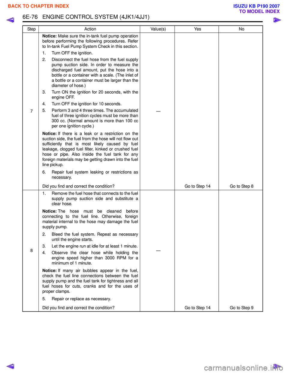
7Notice:
Make sure the in-tank fuel pump operation
before performing the following procedures. Refer
to In-tank Fuel Pump System Check in this section.
1. Turn OFF the ignition.
2. Disconnect the fuel hose from the fuel supply pump suction side. In order to measure the
discharged fuel amount, put the hose into a
bottle or a container with a scale. (The inlet of
a bottle or a container must be larger than the
diameter of hose.)
3. Turn ON the ignition for 20 seconds, with the engine OFF.
4. Turn OFF the ignition for 10 seconds.
5. Perform 3 and 4 three times. The accumulated fuel of three ignition cycles must be more than
300 cc. (Normal amount is more than 100 cc
per one ignition cycle.)
Notice: If there is a leak or a restriction on the
suction side, the fuel from the hose will not flow out
sufficiently that is most likely caused by fuel
leakage, clogged fuel filter, kinked or crushed fuel
hose or pipe. Also inside the fuel tank for any
foreign materials may be getting drawn into the fuel
line pickup.
6. Repair fuel system leaking or restrictions as necessary.
Did you find and correct the condition? —
Go to Step 14 Go to Step 8
8 1. Remove the fuel hose that connects to the fuel
supply pump suction side and substitute a
clear hose.
Notice: The hose must be cleaned before
connecting to the fuel line. Otherwise, foreign
material internal to the hose may damage the fuel
supply pump.
2. Bleed the fuel system. Repeat as necessary until the engine starts.
3. Let the engine run at idle for at least 1 minute.
4. Observe the clear hose while holding the engine speed higher than 3000 RPM for a
minimum of 1 minute.
Notice: If many air bubbles appear in the fuel,
check the fuel line connections between the fuel
supply pump and the fuel tank for tightness and all
fuel hoses for cuts, cranks and for the uses of
proper clamps.
5. Repair or replace as necessary.
Did you find and correct the condition? —
Go to Step 14 Go to Step 9
Step
Action Value(s)Yes No
BACK TO CHAPTER INDEX
TO MODEL INDEX
ISUZU KB P190 2007
Page 1696 of 6020
ENGINE CONTROL SYSTEM (4JK1/4JJ1) 6E-79
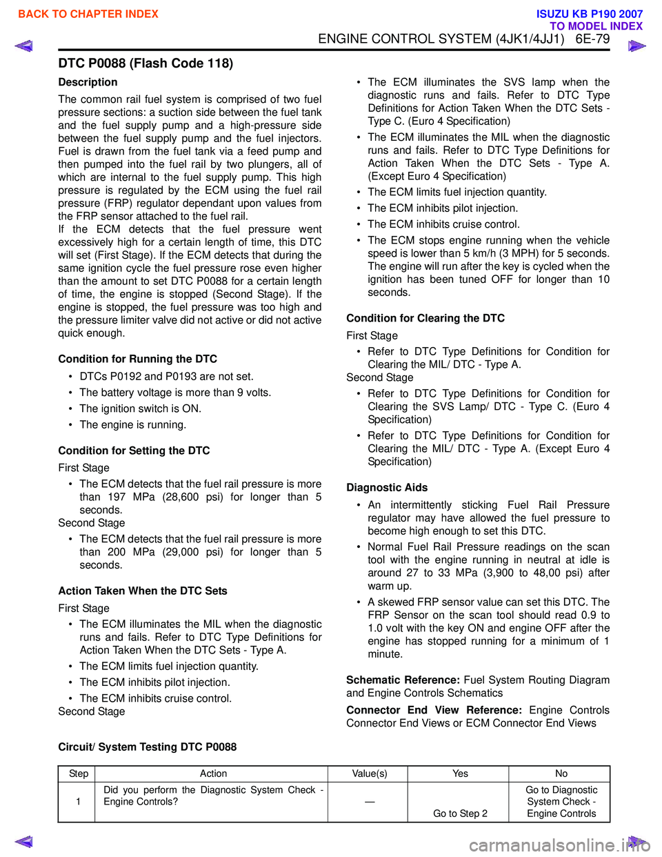
DTC P0088 (Flash Code 118)
Description
The common rail fuel system is comprised of two fuel
pressure sections: a suction side between the fuel tank
and the fuel supply pump and a high-pressure side
between the fuel supply pump and the fuel injectors.
Fuel is drawn from the fuel tank via a feed pump and
then pumped into the fuel rail by two plungers, all of
which are internal to the fuel supply pump. This high
pressure is regulated by the ECM using the fuel rail
pressure (FRP) regulator dependant upon values from
the FRP sensor attached to the fuel rail.
If the ECM detects that the fuel pressure went
excessively high for a certain length of time, this DTC
will set (First Stage). If the ECM detects that during the
same ignition cycle the fuel pressure rose even higher
than the amount to set DTC P0088 for a certain length
of time, the engine is stopped (Second Stage). If the
engine is stopped, the fuel pressure was too high and
the pressure limiter valve did not active or did not active
quick enough.
Condition for Running the DTC • DTCs P0192 and P0193 are not set.
• The battery voltage is more than 9 volts.
• The ignition switch is ON.
• The engine is running.
Condition for Setting the DTC
First Stage • The ECM detects that the fuel rail pressure is more than 197 MPa (28,600 psi) for longer than 5
seconds.
Second Stage
• The ECM detects that the fuel rail pressure is more than 200 MPa (29,000 psi) for longer than 5
seconds.
Action Taken When the DTC Sets
First Stage • The ECM illuminates the MIL when the diagnostic runs and fails. Refer to DTC Type Definitions for
Action Taken When the DTC Sets - Type A.
• The ECM limits fuel injection quantity.
• The ECM inhibits pilot injection.
• The ECM inhibits cruise control.
Second Stage • The ECM illuminates the SVS lamp when the
diagnostic runs and fails. Refer to DTC Type
Definitions for Action Taken When the DTC Sets -
Type C. (Euro 4 Specification)
• The ECM illuminates the MIL when the diagnostic runs and fails. Refer to DTC Type Definitions for
Action Taken When the DTC Sets - Type A.
(Except Euro 4 Specification)
• The ECM limits fuel injection quantity.
• The ECM inhibits pilot injection.
• The ECM inhibits cruise control.
• The ECM stops engine running when the vehicle speed is lower than 5 km/h (3 MPH) for 5 seconds.
The engine will run after the key is cycled when the
ignition has been tuned OFF for longer than 10
seconds.
Condition for Clearing the DTC
First Stage • Refer to DTC Type Definitions for Condition for Clearing the MIL/ DTC - Type A.
Second Stage
• Refer to DTC Type Definitions for Condition for Clearing the SVS Lamp/ DTC - Type C. (Euro 4
Specification)
• Refer to DTC Type Definitions for Condition for Clearing the MIL/ DTC - Type A. (Except Euro 4
Specification)
Diagnostic Aids • An intermittently sticking Fuel Rail Pressure regulator may have allowed the fuel pressure to
become high enough to set this DTC.
• Normal Fuel Rail Pressure readings on the scan tool with the engine running in neutral at idle is
around 27 to 33 MPa (3,900 to 48,00 psi) after
warm up.
• A skewed FRP sensor value can set this DTC. The FRP Sensor on the scan tool should read 0.9 to
1.0 volt with the key ON and engine OFF after the
engine has stopped running for a minimum of 1
minute.
Schematic Reference: Fuel System Routing Diagram
and Engine Controls Schematics
Connector End View Reference: Engine Controls
Connector End Views or ECM Connector End Views
Circuit/ System Testing DTC P0088
Step Action Value(s)Yes No
1 Did you perform the Diagnostic System Check -
Engine Controls? —
Go to Step 2 Go to Diagnostic
System Check -
Engine Controls
BACK TO CHAPTER INDEX
TO MODEL INDEX
ISUZU KB P190 2007