2007 ISUZU KB P190 battery replacement
[x] Cancel search: battery replacementPage 1906 of 6020
ENGINE CONTROL SYSTEM (4JK1/4JJ1) 6E-289
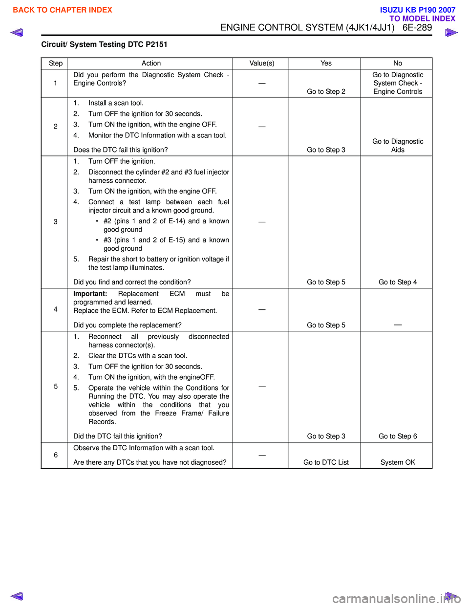
Circuit/ System Testing DTC P2151
StepAction Value(s)Yes No
1 Did you perform the Diagnostic System Check -
Engine Controls? —
Go to Step 2 Go to Diagnostic
System Check -
Engine Controls
2 1. Install a scan tool.
2. Turn OFF the ignition for 30 seconds.
3. Turn ON the ignition, with the engine OFF.
4. Monitor the DTC Information with a scan tool.
Does the DTC fail this ignition? —
Go to Step 3 Go to Diagnostic
Aids
3 1. Turn OFF the ignition.
2. Disconnect the cylinder #2 and #3 fuel injector harness connector.
3. Turn ON the ignition, with the engine OFF.
4. Connect a test lamp between each fuel injector circuit and a known good ground.
• #2 (pins 1 and 2 of E-14) and a known good ground
• #3 (pins 1 and 2 of E-15) and a known good ground
5. Repair the short to battery or ignition voltage if the test lamp illuminates.
Did you find and correct the condition? —
Go to Step 5 Go to Step 4
4 Important:
Replacement ECM must be
programmed and learned.
Replace the ECM. Refer to ECM Replacement.
Did you complete the replacement? —
Go to Step 5
—
51. Reconnect all previously disconnected
harness connector(s).
2. Clear the DTCs with a scan tool.
3. Turn OFF the ignition for 30 seconds.
4. Turn ON the ignition, with the engineOFF.
5. Operate the vehicle within the Conditions for Running the DTC. You may also operate the
vehicle within the conditions that you
observed from the Freeze Frame/ Failure
Records.
Did the DTC fail this ignition? —
Go to Step 3 Go to Step 6
6 Observe the DTC Information with a scan tool.
Are there any DTCs that you have not diagnosed? —
Go to DTC List System OK
BACK TO CHAPTER INDEX
TO MODEL INDEX
ISUZU KB P190 2007
Page 1916 of 6020
ENGINE CONTROL SYSTEM (4JK1/4JJ1) 6E-299
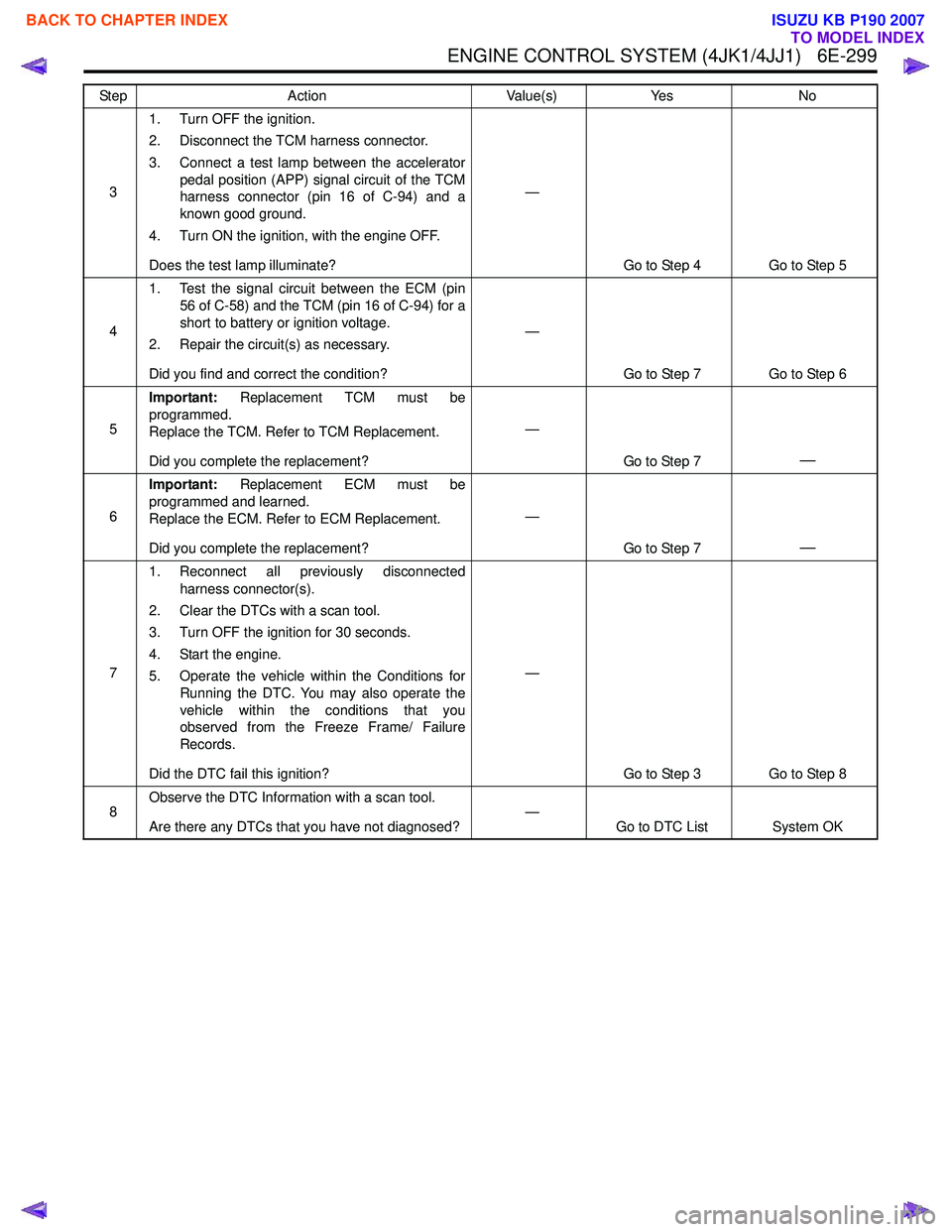
31. Turn OFF the ignition.
2. Disconnect the TCM harness connector.
3. Connect a test lamp between the accelerator pedal position (APP) signal circuit of the TCM
harness connector (pin 16 of C-94) and a
known good ground.
4. Turn ON the ignition, with the engine OFF.
Does the test lamp illuminate? —
Go to Step 4 Go to Step 5
4 1. Test the signal circuit between the ECM (pin
56 of C-58) and the TCM (pin 16 of C-94) for a
short to battery or ignition voltage.
2. Repair the circuit(s) as necessary.
Did you find and correct the condition? —
Go to Step 7 Go to Step 6
5 Important:
Replacement TCM must be
programmed.
Replace the TCM. Refer to TCM Replacement.
Did you complete the replacement? —
Go to Step 7
—
6Important:
Replacement ECM must be
programmed and learned.
Replace the ECM. Refer to ECM Replacement.
Did you complete the replacement? —
Go to Step 7
—
71. Reconnect all previously disconnected
harness connector(s).
2. Clear the DTCs with a scan tool.
3. Turn OFF the ignition for 30 seconds.
4. Start the engine.
5. Operate the vehicle within the Conditions for Running the DTC. You may also operate the
vehicle within the conditions that you
observed from the Freeze Frame/ Failure
Records.
Did the DTC fail this ignition? —
Go to Step 3 Go to Step 8
8 Observe the DTC Information with a scan tool.
Are there any DTCs that you have not diagnosed? —
Go to DTC List System OK
Step
Action Value(s)Yes No
BACK TO CHAPTER INDEX
TO MODEL INDEX
ISUZU KB P190 2007
Page 1925 of 6020
6E-308 ENGINE CONTROL SYSTEM (4JK1/4JJ1)
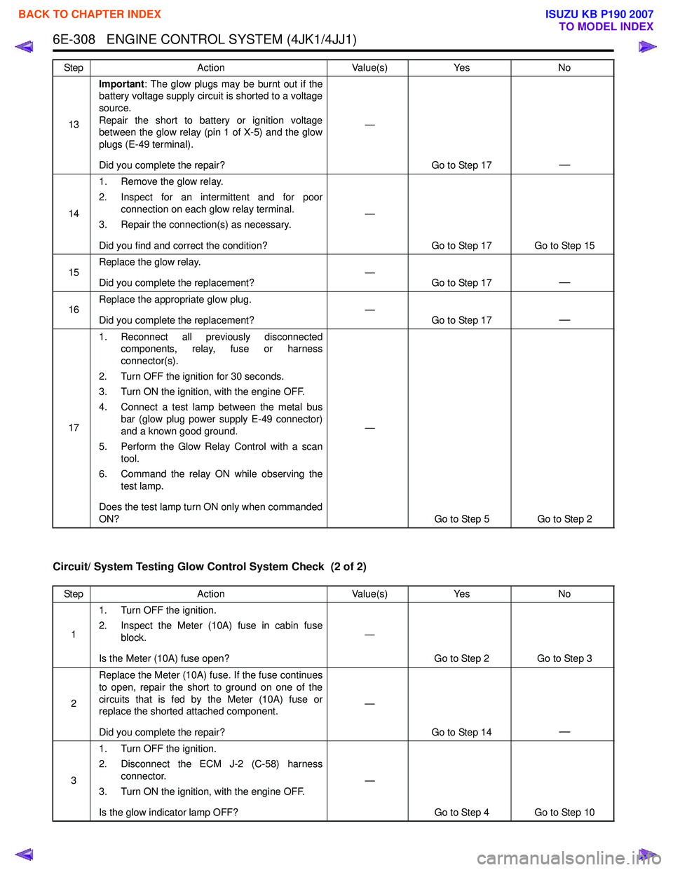
Circuit/ System Testing Glow Control System Check (2 of 2)
13Important
: The glow plugs may be burnt out if the
battery voltage supply circuit is shorted to a voltage
source.
Repair the short to battery or ignition voltage
between the glow relay (pin 1 of X-5) and the glow
plugs (E-49 terminal).
Did you complete the repair? —
Go to Step 17
—
141. Remove the glow relay.
2. Inspect for an intermittent and for poor connection on each glow relay terminal.
3. Repair the connection(s) as necessary.
Did you find and correct the condition? —
Go to Step 17 Go to Step 15
15 Replace the glow relay.
Did you complete the replacement? —
Go to Step 17
—
16Replace the appropriate glow plug.
Did you complete the replacement? —
Go to Step 17—
171. Reconnect all previously disconnected
components, relay, fuse or harness
connector(s).
2. Turn OFF the ignition for 30 seconds.
3. Turn ON the ignition, with the engine OFF.
4. Connect a test lamp between the metal bus bar (glow plug power supply E-49 connector)
and a known good ground.
5. Perform the Glow Relay Control with a scan tool.
6. Command the relay ON while observing the test lamp.
Does the test lamp turn ON only when commanded
ON? —
Go to Step 5 Go to Step 2
Step
Action Value(s)Yes No
Step Action Value(s)Yes No
1 1. Turn OFF the ignition.
2. Inspect the Meter (10A) fuse in cabin fuse block.
Is the Meter (10A) fuse open? —
Go to Step 2 Go to Step 3
2 Replace the Meter (10A) fuse. If the fuse continues
to open, repair the short to ground on one of the
circuits that is fed by the Meter (10A) fuse or
replace the shorted attached component.
Did you complete the repair? —
Go to Step 14
—
31. Turn OFF the ignition.
2. Disconnect the ECM J-2 (C-58) harness connector.
3. Turn ON the ignition, with the engine OFF.
Is the glow indicator lamp OFF? —
Go to Step 4 Go to Step 10
BACK TO CHAPTER INDEX
TO MODEL INDEX
ISUZU KB P190 2007
Page 1934 of 6020
ENGINE CONTROL SYSTEM (4JK1/4JJ1) 6E-317
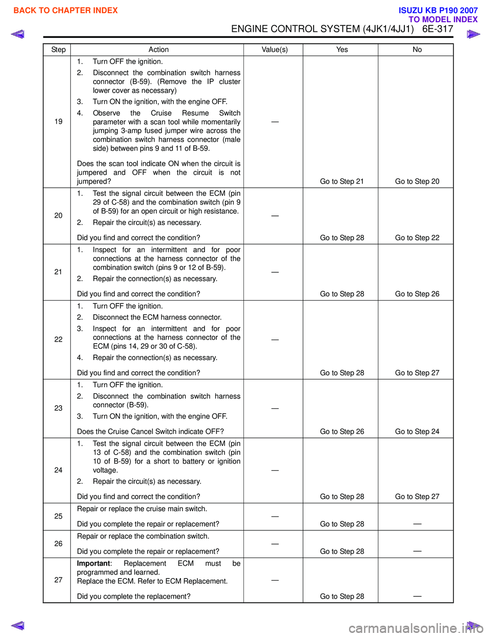
191. Turn OFF the ignition.
2. Disconnect the combination switch harness connector (B-59). (Remove the IP cluster
lower cover as necessary)
3. Turn ON the ignition, with the engine OFF.
4. Observe the Cruise Resume Switch parameter with a scan tool while momentarily
jumping 3-amp fused jumper wire across the
combination switch harness connector (male
side) between pins 9 and 11 of B-59.
Does the scan tool indicate ON when the circuit is
jumpered and OFF when the circuit is not
jumpered? —
Go to Step 21 Go to Step 20
20 1. Test the signal circuit between the ECM (pin
29 of C-58) and the combination switch (pin 9
of B-59) for an open circuit or high resistance.
2. Repair the circuit(s) as necessary.
Did you find and correct the condition? —
Go to Step 28 Go to Step 22
21 1. Inspect for an intermittent and for poor
connections at the harness connector of the
combination switch (pins 9 or 12 of B-59).
2. Repair the connection(s) as necessary.
Did you find and correct the condition? —
Go to Step 28 Go to Step 26
22 1. Turn OFF the ignition.
2. Disconnect the ECM harness connector.
3. Inspect for an intermittent and for poor connections at the harness connector of the
ECM (pins 14, 29 or 30 of C-58).
4. Repair the connection(s) as necessary.
Did you find and correct the condition? —
Go to Step 28 Go to Step 27
23 1. Turn OFF the ignition.
2. Disconnect the combination switch harness connector (B-59).
3. Turn ON the ignition, with the engine OFF.
Does the Cruise Cancel Switch indicate OFF? —
Go to Step 26 Go to Step 24
24 1. Test the signal circuit between the ECM (pin
13 of C-58) and the combination switch (pin
10 of B-59) for a short to battery or ignition
voltage.
2. Repair the circuit(s) as necessary.
Did you find and correct the condition? —
Go to Step 28 Go to Step 27
25 Repair or replace the cruise main switch.
Did you complete the repair or replacement? —
Go to Step 28
—
26Repair or replace the combination switch.
Did you complete the repair or replacement? —
Go to Step 28—
27Important
: Replacement ECM must be
programmed and learned.
Replace the ECM. Refer to ECM Replacement.
Did you complete the replacement? —
Go to Step 28
—
Step Action Value(s)Yes No
BACK TO CHAPTER INDEX
TO MODEL INDEX
ISUZU KB P190 2007
Page 1936 of 6020
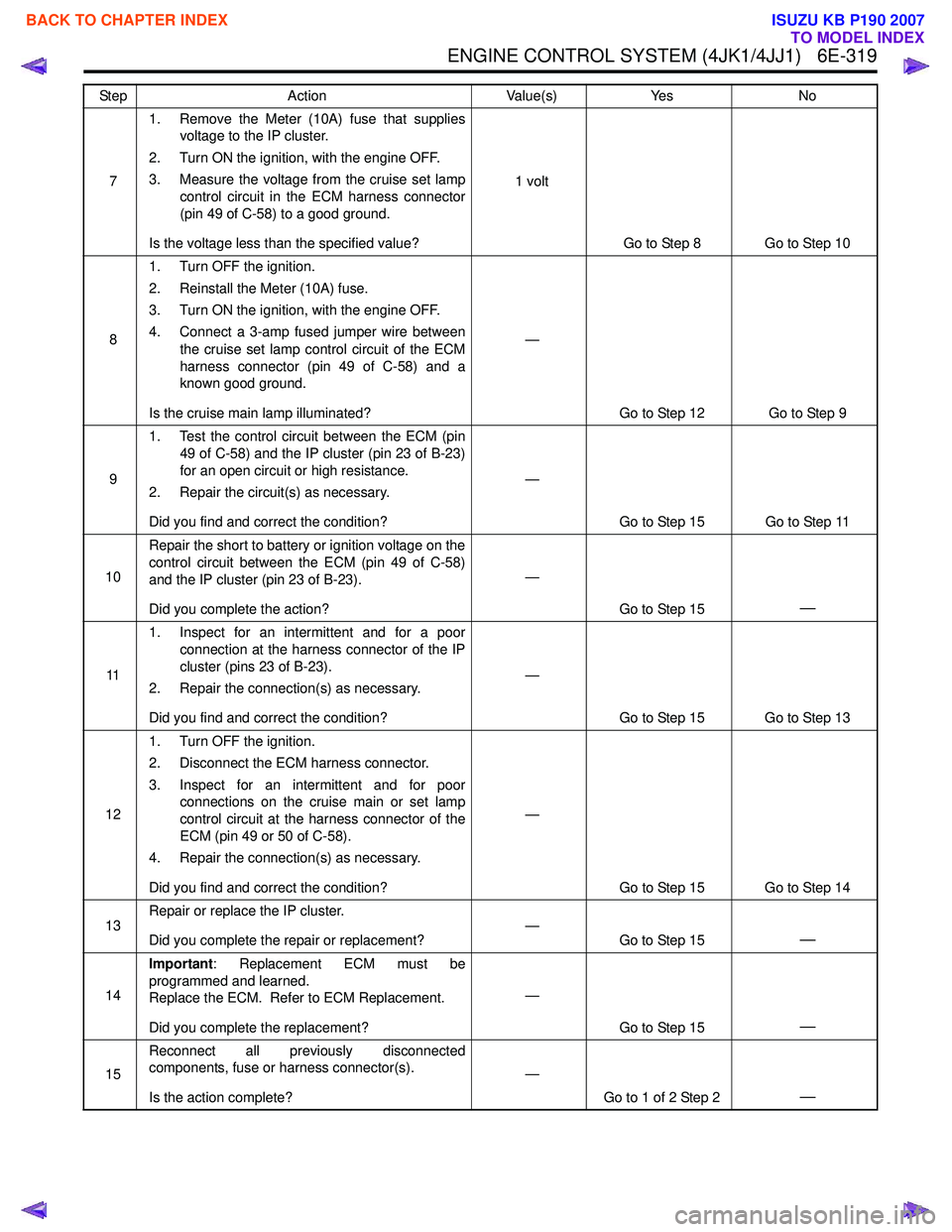
ENGINE CONTROL SYSTEM (4JK1/4JJ1) 6E-319
71. Remove the Meter (10A) fuse that supplies
voltage to the IP cluster.
2. Turn ON the ignition, with the engine OFF.
3. Measure the voltage from the cruise set lamp control circuit in the ECM harness connector
(pin 49 of C-58) to a good ground.
Is the voltage less than the specified value? 1 volt
Go to Step 8 Go to Step 10
8 1. Turn OFF the ignition.
2. Reinstall the Meter (10A) fuse.
3. Turn ON the ignition, with the engine OFF.
4. Connect a 3-amp fused jumper wire between the cruise set lamp control circuit of the ECM
harness connector (pin 49 of C-58) and a
known good ground.
Is the cruise main lamp illuminated? —
Go to Step 12 Go to Step 9
9 1. Test the control circuit between the ECM (pin
49 of C-58) and the IP cluster (pin 23 of B-23)
for an open circuit or high resistance.
2. Repair the circuit(s) as necessary.
Did you find and correct the condition? —
Go to Step 15 Go to Step 11
10 Repair the short to battery or ignition voltage on the
control circuit between the ECM (pin 49 of C-58)
and the IP cluster (pin 23 of B-23).
Did you complete the action? —
Go to Step 15
—
111. Inspect for an intermittent and for a poor
connection at the harness connector of the IP
cluster (pins 23 of B-23).
2. Repair the connection(s) as necessary.
Did you find and correct the condition? —
Go to Step 15 Go to Step 13
12 1. Turn OFF the ignition.
2. Disconnect the ECM harness connector.
3. Inspect for an intermittent and for poor connections on the cruise main or set lamp
control circuit at the harness connector of the
ECM (pin 49 or 50 of C-58).
4. Repair the connection(s) as necessary.
Did you find and correct the condition? —
Go to Step 15 Go to Step 14
13 Repair or replace the IP cluster.
Did you complete the repair or replacement? —
Go to Step 15
—
14Important
: Replacement ECM must be
programmed and learned.
Replace the ECM. Refer to ECM Replacement.
Did you complete the replacement? —
Go to Step 15
—
15Reconnect all previously disconnected
components, fuse or harness connector(s).
Is the action complete? —
Go to 1 of 2 Step 2
—
Step Action Value(s)Yes No
BACK TO CHAPTER INDEX
TO MODEL INDEX
ISUZU KB P190 2007
Page 2111 of 6020
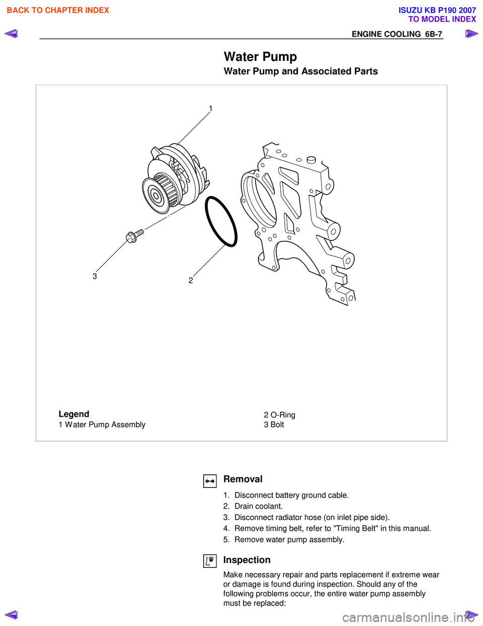
ENGINE COOLING 6B-7
Water Pump
Water Pump and Associated Parts
Legend
1 Water Pump Assembly 2 O-Ring
3 Bolt
2
3 1
Removal
1. Disconnect battery ground cable.
2. Drain coolant.
3. Disconnect radiator hose (on inlet pipe side).
4. Remove timing belt, refer to "Timing Belt" in this manual.
5. Remove water pump assembly.
Inspection
Make necessary repair and parts replacement if extreme wear
or damage is found during inspection. Should any of the
following problems occur, the entire water pump assembly
must be replaced:
BACK TO CHAPTER INDEX
TO MODEL INDEX
ISUZU KB P190 2007
Page 2113 of 6020
ENGINE COOLING 6B-9
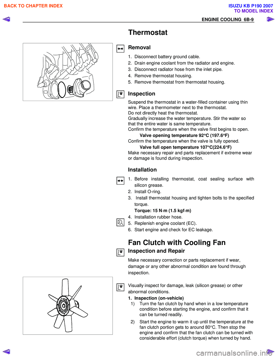
Thermostat
Removal
1. Disconnect battery ground cable.
2. Drain engine coolant from the radiator and engine.
3. Disconnect radiator hose from the inlet pipe.
4. Remove thermostat housing.
5. Remove thermostat from thermostat housing.
Inspection
Suspend the thermostat in a water-filled container using thin
wire. Place a thermometer next to the thermostat.
Do not directly heat the thermostat.
Gradually increase the water temperature. Stir the water so
that the entire water is same temperature.
Confirm the temperature when the valve first begins to open.
Valve opening temperature 92 °
°°
°
C (197.6 °
°°
°
F)
Confirm the temperature when the valve is fully opened.
Valve full open temperature 107 °
°°
°
C(224.6 °
°°
°
F)
Make necessary repair and parts replacement if extreme wear
or damage is found during inspection.
Installation
1. Before installing thermostat, coat sealing surface with
silicon grease.
2. Install O-ring.
3. Install thermostat housing and tighten bolts to the specified torque.
Torque: 15 N ⋅
⋅⋅
⋅
m (1.5 kgf ⋅
⋅⋅
⋅
m)
4. Installation rubber hose.
5. Replenish engine coolant (EC).
6. Start engine and check for EC leakage.
Fan Clutch with Cooling Fan
Inspection and Repair
Make necessary correction or parts replacement if wear,
damage or any other abnormal condition are found through
inspection.
Visually inspect for damage, leak (silicon grease) or other
abnormal conditions.
1. Inspection (on-vehicle)
1) Turn the fan clutch by hand when in a low temperature condition before starting the engine, and confirm that it
can be turned readily.
2) Start the engine to warm it up until the temperature at the fan clutch portion gets to around 80 °C. Then stop the
engine and confirm that the fan clutch can be turned with
considerable effort (clutch torque) when turned by hand.
BACK TO CHAPTER INDEX
TO MODEL INDEX
ISUZU KB P190 2007
Page 2121 of 6020
ENGINE FUEL (C24SE) 6C-3
W hen working on the fuel system, there are several things to
keep in mind:
•
Any time the fuel system is being worked on, disconnect the
negative battery cable except for those tests where batter
y
voltage is required.
•
Always keep a dry chemical (Class B) fire extinguisher near
the work area.
• Replace all pipes with the same pipe and fittings that were
removed.
• Clean and inspect "O" rings. Replace if required.
•
Always relieve the line pressure before servicing any fuel
system components.
• Do not attempt repairs on the fuel system until you have
read the instructions and checked the pictures relating to
that repair.
• Adhere to all Notices and Cautions.
All gasoline engines are designed to use only unleaded
gasoline. Unleaded gasoline must be used for proper emission
control system operation.
Its use will also minimize spark plug fouling and extend engine
oil life. Using leaded gasoline can damage the emission control
system and could result in loss of emission warranty coverage.
All cars are equipped with an Evaporative Emission Control
System. The purpose of the system is to minimize the escape
of fuel vapors to the atmosphere.
Service Precaution
CAUTION:
Always use the correct fastener in the proper location.
When you replace a fastener, use ONLY the exact part
number for that application. ISUZU will call out those
fasteners that require a replacement after removal. ISUZU
will also call out the fasteners that require thread lockers
or thread sealant. UNLESS OTHERWISE SPECIFIED, do
not use supplemental coatings (Paints, greases, or othe
r
corrosion inhibitors) on threaded fasteners or fastene
r
joint interfaces. Generally, such coatings adversely affect
the fastener torque and the joint clamping force, and may
damage the fastener. When you install fasteners, use the
correct tightening sequence and specifications. Following
these instructions can help you avoid damage to parts
and systems.
BACK TO CHAPTER INDEX
TO MODEL INDEX
ISUZU KB P190 2007