2007 ISUZU KB P190 battery replacement
[x] Cancel search: battery replacementPage 2139 of 6020
6D1-2 ENGINE ELECTRICAL
Battery
General Description
There are six battery fluid caps on top of the battery.
These are covered by a paper label.
The battery is completely sealed except for the six small vent
holes on the side. These vent holes permit the escape of small
amounts of gas generated by the battery.
This type of battery has the following advantages over
conventional batteries:
1. There is no need to add water during the entire service life
of the battery.
2. The battery protects itself against overcharging.
The battery will refuse to accept an extensive charge.
(A conventional battery will accept an excessive charge, resulting in gassing and loss of battery fluid.)
3. The battery is much less vulnerable to self discharge than a conventional type battery.
Service Precaution
CAUTION:
Always use the correct fastener in the proper location.
When you replace a fastener, use ONLY the exact part
number for that application. ISUZU will call out those
fasteners that require a replacement after removal. ISUZU
will also call out the fasteners that require thread lockers
or thread sealant. UNLESS OTHERWISE SPECIFIED, do
not use supplemental coatings (Paints, greases, or other
corrosion inhibitors) on threaded fasteners or fastener
joint interfaces. Generally, such coatings adversely affect
the fastener torque and the joint clamping force, and may
damage the fastener. When you install fasteners, use the
correct tightening sequence and specifications. Following
these instructions can help you avoid damage to parts
and systems.
BACK TO CHAPTER INDEX
TO MODEL INDEX
ISUZU KB P190 2007
Page 2145 of 6020
6D2-2 IGNITION SYSTEM
General Description
Ignition is done by the Ignition Module that fires.
Since the cylinder on exhaust stroke requires less energy to
fire its spark plug, energy from the ignition coils can be utilized
to fire the mating cylinder on compression stroke.
A notch in the timing disc on the crankshaft activates the crank
angle sensor which then sends information such as firing order
and starting timing of ignition coil to the ECM.
By receiving signals such as crank position, engine speed,
water temperature and Manifold Absolute Pressure (MAP), the
ECM controls the ignition timing.
Service Precaution
CAUTION:
Always use the correct fastener in the proper location.
When you replace a fastener, use ONLY the exact part
number for that application. ISUZU will call out those
fasteners that require a replacement after removal. ISUZU
will also call out the fasteners that require thread lockers
or thread sealant. UNLESS OTHERWISE SPECIFIED, do
not use supplemental coatings (Paints, greases, or other
corrosion inhibitors) on threaded fasteners or fastener
joint interfaces. Generally, such coatings adversely affect
the fastener torque and the joint clamping force, and may
damage the fastener. When you install fasteners, use the
correct tightening sequence and specifications. Following
these instructions can help you avoid damage to parts
and systems.
Diagnosis
Refer to Section Drivability and Emissions for the diagnosis to
electronic ignition system (El system).
Ignition Coil
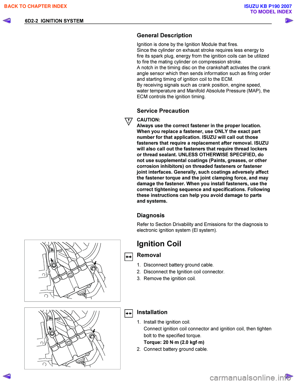
Removal
1. Disconnect battery ground cable.
2. Disconnect the Ignition coil connector.
3. Remove the ignition coil.
Installation
1. Install the ignition coil.
Connect ignition coil connector and ignition coil, then tighten bolt to the specified torque.
Torque: 20 N ⋅m (2.0 kgf ⋅m)
2. Connect battery ground cable.
BACK TO CHAPTER INDEX
TO MODEL INDEX
ISUZU KB P190 2007
Page 2150 of 6020
6D3-2 STARTING AND CHARGING SYSTEM
Starting System
General Description
Cranking Circuit
The cranking system consists of a battery, starter, starter
switch, starter relay, etc. These main components are
connected.
Starter
The cranking system employs a magnetic type reduction
starter in which the motor shaft is also used as a pinion shaft.
W hen the starter switch is turned on, the contacts of magnetic
switch are closed, and the armature rotates. At the same time,
the plunger is attracted, and the pinion is pushed forward by
the shift lever to mesh with the ring gear.
Then, the ring gear runs to start the engine. W hen the engine
starts and the starter switch is turned off, the plunger returns,
the pinion is disengaged from the ring gear, and the armature
stops rotation. W hen the engine speed is higher than the
pinion, the pinion idles, so that the armature is not driven.
Service Precaution
CAUTION:
Always use the correct fastener in the proper location.
When you replace a fastener, use ONLY the exact part
number for that application. ISUZU will call out those
fasteners that require a replacement after removal. ISUZU
will also call out the fasteners that require thread lockers
or thread sealant. UNLESS OTHERWISE SPECIFIED, do
not use supplemental coatings (Paints, greases, or other
corrosion inhibitors) on threaded fasteners or fastener
joint interfaces. Generally, such coatings adversely affect
the fastener torque and the joint clamping force, and may
damage the fastener. When you install fasteners, use the
correct tightening sequence and specifications. Following
these instructions can help you avoid damage to parts
and systems.
Diagnosis
Condition Possible cause Correction
Starter does not run Charging failure Repair charging system
Battery Failure Replace Battery
Terminal connection failure Repair or replace terminal connector
and/or wiring harness
Starter switch failure Repair or replace starter switch
Starter failure Repair or replace starter
BACK TO CHAPTER INDEX
TO MODEL INDEX
ISUZU KB P190 2007
Page 2224 of 6020
6E–54 ENGINE DRIVEABILITY AND EMISSIONS
GENERAL DESCRIPTION FOR ELECTRIC
IGNITION SYSTEM
The engine use two ignition coils, one per two cylinders.
A two wire connector provides a battery voltage primary
supply through the ignition fuse.
The ignition control spark timing is the ECM’s method of
controlling the spark advance and the ignition dwell.
The ignition control spark advance and the ignition dwell
are calculated by the ECM using the following inputs.
• Engine speed
• Crankshaft position (CKP) sensor
• Engine coolant temperature (ECT) sensor
• Throttle position sensor
• Vehicle speed sensor
• ECM and ignition system supply voltage
Ignition coil works to generate only the secondary
voltage be receiving the primary voltage from ECM.
The primary voltage is generated at the coil driver
located in the ECM. The coil driver generate the primary
voltage based on the crankshaft position signal. In
accordance with the crankshaft position signal, ignition
coil driver determines the adequate ignition timing and
also cylinder number to ignite.
Ignition timing is determined the coolant temperature,
intake air temperature, engine speed, engine load,
knock sensor signal, etc.
Spark Plug
Although worn or dirty spark plugs may give satisfactory
operation at idling speed, they frequently fail at higher
engine speeds. Faulty spark plugs may cause poor fuel
economy, power loss, loss of speed, hard starting and
generally poor engine performance. Follow the
scheduled maintenance service recommendations to
ensure satisfactory spark plug performance. Refer to
Maintenance and Lubrication .
Normal spark plug operation will result in brown to
grayish-tan deposits appearing on the insulator portion
of the spark plug. A small amount of red-brown, yellow,
and white powdery material may also be present on the
insulator tip around the center electrode. These
deposits are normal combustion by-products of fuels
and lubricating oils with additives. Some electrode wear
will also occur. Engines which are not running properly
are often referred to as “misfiring.” This means the
ignition spark is not igniting the air/fuel mixture at the
proper time. While other ignition and fuel system causes
must also be considered, possible causes include
ignition system conditions which allow the spark voltage
to reach ground in some other manner than by jumping
across the air gap at the tip of the spark plug, leaving
the air/fuel mixture unburned. Misfiring may also occur
when the tip of the spark plug becomes overheated and
ignites the mixture before the spark jumps. This is
referred to as “pre-ignition.”
Spark plugs may also misfire due to fouling, excessive
gap, or a cracked or broken insulator. If misfiring occurs before the recommended replacement interval, locate
and correct the cause.
Carbon fouling of the spark plug is indicated by dry,
black carbon (soot) deposits on the portion of the spark
plug in the cylinder. Excessive idling and slow speeds
under light engine loads can keep the spark plug
temperatures so low that these deposits are not burned
off. Very rich fuel mixtures or poor ignition system output
may also be the cause. Refer to DTC P1167.
Oil fouling of the spark plug is indicated by wet oily
deposits on the portion of the spark plug in the cylinder,
usually with little electrode wear. This may be caused by
oil during break-in of new or newly overhauled engines.
Deposit fouling of the spark plug occurs when the
normal red-brown, yellow or white deposits of
combustion by-products become sufficient to cause
misfiring. In some cases, these deposits may melt and
form a shiny glaze on the insulator around the center
electrode. If the fouling is found in only one or two
cylinders, valve stem clearances or intake valve seals
may be allowing excess lubricating oil to enter the
cylinder, particularly if the deposits are heavier on the
side of the spark plug facing the intake valve.
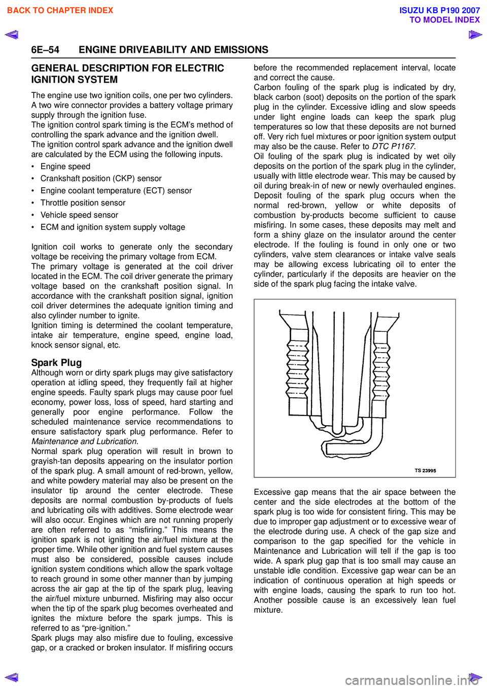
Excessive gap means that the air space between the
center and the side electrodes at the bottom of the
spark plug is too wide for consistent firing. This may be
due to improper gap adjustment or to excessive wear of
the electrode during use. A check of the gap size and
comparison to the gap specified for the vehicle in
Maintenance and Lubrication will tell if the gap is too
wide. A spark plug gap that is too small may cause an
unstable idle condition. Excessive gap wear can be an
indication of continuous operation at high speeds or
with engine loads, causing the spark to run too hot.
Another possible cause is an excessively lean fuel
mixture.
BACK TO CHAPTER INDEX
TO MODEL INDEX
ISUZU KB P190 2007
Page 2254 of 6020
6E–84 ENGINE DRIVEABILITY AND EMISSIONS
SERVICE PROGRAMMING SYSTEM (SPS)
The procedure to program the control unit by using the
Service Programming System (SPS) software contained
in TIS2000 is explained below.
NOTE:
• If the Engine Control Module (ECM) was programmed, the Immobilizer System must be
linked to the ECM: Refer to section 11
“Immobilizer System-ECM replacement” for the
ECM/Immobilizer linking procedure.
• Should Tech2 display "SPS Procedure was not successful", engine will not start, but no DTCs
are present, low battery voltage or poor electrical
connections should be the primary suspects.
Perform the SPS procedure again after rectifying
the fault/s. IMPORTANT:
Perform the following checks before attempting to
program the control unit:
• The Tech2 PCMCIA card is programmed with The latest software release.
• The latest release of TIS2000 is loaded on the PC.
• The vehicle battery is fully charged.
• The control unit to be programmed is connected to the vehicle.
1. Preparations of TIS 2000 1. Connect Tech 2 to P/C.
2. Check to see if Hardware Key is plugged into Port.
3. Activate TIS 2000 by P/C.
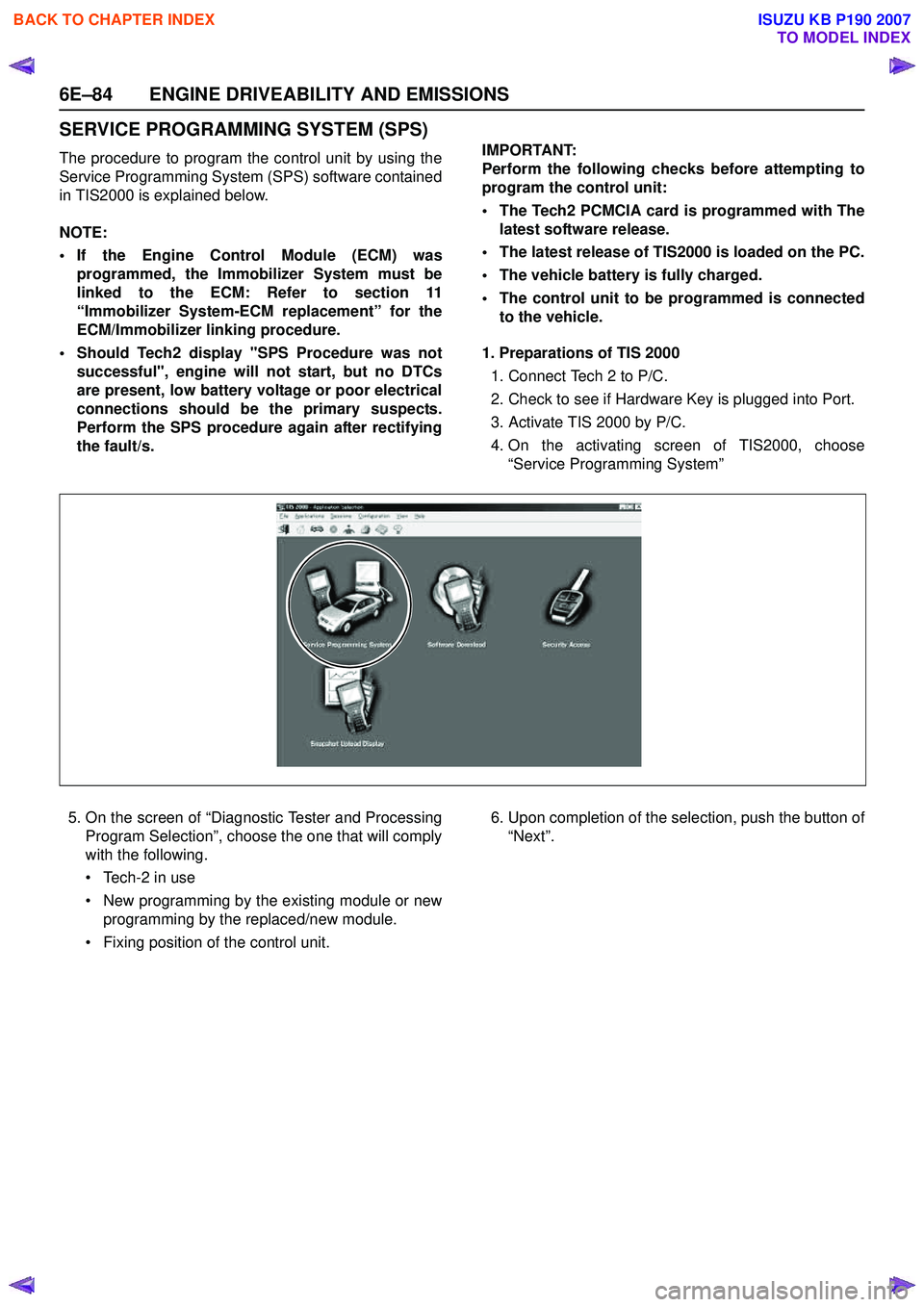
4. On the activating screen of TIS2000, choose “Service Programming System”
5. On the screen of “Diagnostic Tester and Processing Program Selection”, choose the one that will comply
with the following.
• Tech-2 in use
• New programming by the existing module or new programming by the replaced/new module.
• Fixing position of the control unit. 6. Upon completion of the selection, push the button of
“Next”.
BACK TO CHAPTER INDEX
TO MODEL INDEX
ISUZU KB P190 2007
Page 2373 of 6020
ENGINE DRIVEABILITY AND EMISSIONS 6E–203
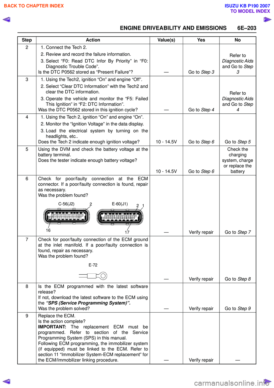
2 1. Connect the Tech 2. 2. Review and record the failure information.
3. Select “F0: Read DTC Infor By Priority” in “F0: Diagnostic Trouble Code”.
Is the DTC P0562 stored as “Present Failure”? — Go to Step 3Refer to
Diagnostic Aids and Go to Step
3
3 1. Using the Tech2, ignition “On” and engine “Off”. 2. Select “Clear DTC Information” with the Tech2 andclear the DTC information.
3. Operate the vehicle and monitor the “F5: Failed This Ignition” in “F2: DTC Information”.
Was the DTC P0562 stored in this ignition cycle? — Go to Step 4Refer to
Diagnostic Aids and Go to Step
4
4 1. Using the Tech 2, ignition “On” and engine “On”. 2. Monitor the “Ignition Voltage” in the data display.
3. Load the electrical system by turning on the headlights, etc..
Does the Tech 2 indicate enough ignition voltage? 10 - 14.5V Go to Step 6Go to Step 5
5 Using the DVM and check the battery voltage at the battery terminal.
Does the tester indicate enough battery voltage?
10 - 14.5V Go to Step 6Check the
charging
system, charge or replace the battery
6 Check for poor/faulty connection at the ECM connector. If a poor/faulty connection is found, repair
as necessary.
Was the problem found?
— Verify repair Go to Step 7
7 Check for poor/faulty connection of the ECM ground at the inlet manifold. If a poor/faulty connection is
found, repair as necessary.
Was the problem found?
— Verify repair Go to Step 8
8 Is the ECM programmed with the latest software release?
If not, download the latest software to the ECM using
the “SPS (Service Programming System)”.
Was the problem solved? — Verify repair Go to Step 9
9 Replace the ECM. Is the action complete?
IMPORTANT: The replacement ECM must be
programmed. Refer to section of the Service
Programming System (SPS) in this manual.
Following ECM programming, the immobilizer system
(if equipped) must be linked to the ECM. Refer to
section 11 “Immobilizer System-ECM replacement” for
the ECM/Immobilizer linking procedure. — Verify repair —
Step
Action Value(s) Yes No
16
2
17
12
C-56(J2)
E-60(J1)
E-72
BACK TO CHAPTER INDEX
TO MODEL INDEX
ISUZU KB P190 2007
Page 2375 of 6020
ENGINE DRIVEABILITY AND EMISSIONS 6E–205
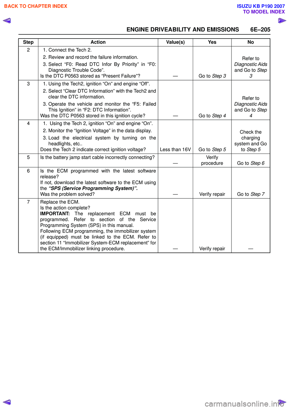
2 1. Connect the Tech 2. 2. Review and record the failure information.
3. Select “F0: Read DTC Infor By Priority” in “F0: Diagnostic Trouble Code”.
Is the DTC P0563 stored as “Present Failure”? — Go to Step 3Refer to
Diagnostic Aids and Go to Step
3
3 1. Using the Tech2, ignition “On” and engine “Off”. 2. Select “Clear DTC Information” with the Tech2 andclear the DTC information.
3. Operate the vehicle and monitor the “F5: Failed This Ignition” in “F2: DTC Information”.
Was the DTC P0563 stored in this ignition cycle? — Go to Step 4Refer to
Diagnostic Aids and Go to Step
4
4 1. Using the Tech 2, ignition “On” and engine “On”. 2. Monitor the “Ignition Voltage” in the data display.
3. Load the electrical system by turning on the headlights, etc..
Does the Tech 2 indicate correct ignition voltage? Less than 16V Go to Step 5Check the
charging
system and Go to Step 5
5 Is the battery jamp start cable incorrectly connecting? —Ve r if y
procedure Go to Step 6
6 Is the ECM programmed with the latest software release?
If not, download the latest software to the ECM using
the “SPS (Service Programming System)”.
Was the problem solved? — Verify repair Go to Step 7
7 Replace the ECM. Is the action complete?
IMPORTANT: The replacement ECM must be
programmed. Refer to section of the Service
Programming System (SPS) in this manual.
Following ECM programming, the immobilizer system
(if equipped) must be linked to the ECM. Refer to
section 11 “Immobilizer System-ECM replacement” for
the ECM/Immobilizer linking procedure. — Verify repair —
Step
Action Value(s) Yes No
BACK TO CHAPTER INDEX
TO MODEL INDEX
ISUZU KB P190 2007
Page 2403 of 6020
ENGINE DRIVEABILITY AND EMISSIONS 6E–233
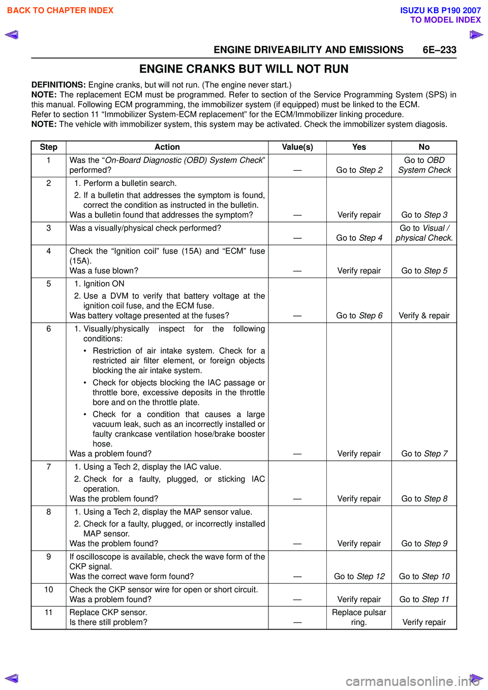
ENGINE CRANKS BUT WILL NOT RUN
DEFINITIONS: Engine cranks, but will not run. (The engine never start.)
NOTE: The replacement ECM must be programmed. Refer to section of the Service Programming System (SPS) in
this manual. Following ECM programming, the immobilizer system (if equipped) must be linked to the ECM.
Refer to section 11 “Immobilizer System-ECM replacement” for the ECM/Immobilizer linking procedure.
NOTE: The vehicle with immobilizer system, this system may be activated. Check the immobilizer system diagosis.
Step Action Value(s) Yes No
1 Was the “ On-Board Diagnostic (OBD) System Check ”
performed? — Go to Step 2Go to
OBD
System Check
2 1. Perform a bulletin search. 2. If a bulletin that addresses the symptom is found,correct the condition as instructed in the bulletin.
Was a bulletin found that addresses the symptom? — Verify repair Go to Step 3
3 Was a visually/physical check performed? —Go to Step 4Go to
Visual /
physical Check.
4 Check the “Ignition coil” fuse (15A) and “ECM” fuse (15A).
Was a fuse blown? — Verify repair Go to Step 5
5 1. Ignition ON 2. Use a DVM to verify that battery voltage at theignition coil fuse, and the ECM fuse.
Was battery voltage presented at the fuses? — Go to Step 6Verify & repair
6 1. Visually/physically inspect for the following conditions:
• Restriction of air intake system. Check for a restricted air filter element, or foreign objects
blocking the air intake system.
• Check for objects blocking the IAC passage or throttle bore, excessive deposits in the throttle
bore and on the throttle plate.
• Check for a condition that causes a large vacuum leak, such as an incorrectly installed or
faulty crankcase ventilation hose/brake booster
hose.
Was a problem found? — Verify repair Go to Step 7
7 1. Using a Tech 2, display the IAC value. 2. Check for a faulty, plugged, or sticking IACoperation.
Was the problem found? — Verify repair Go to Step 8
8 1. Using a Tech 2, display the MAP sensor value. 2. Check for a faulty, plugged, or incorrectly installedMAP sensor.
Was the problem found? — Verify repair Go to Step 9
9 If oscilloscope is available, check the wave form of the CKP signal.
Was the correct wave form found? — Go to Step 12Go to Step 10
10 Check the CKP sensor wire for open or short circuit. Was a problem found? — Verify repair Go to Step 11
11 Replace CKP sensor. Is there still problem? —Replace pulsar
ring. Verify repair
BACK TO CHAPTER INDEX
TO MODEL INDEX
ISUZU KB P190 2007