2007 ISUZU KB P190 battery replacement
[x] Cancel search: battery replacementPage 3893 of 6020
Automatic Transmission – 4L60E – Electrical Diagnosis Page 7C2–107
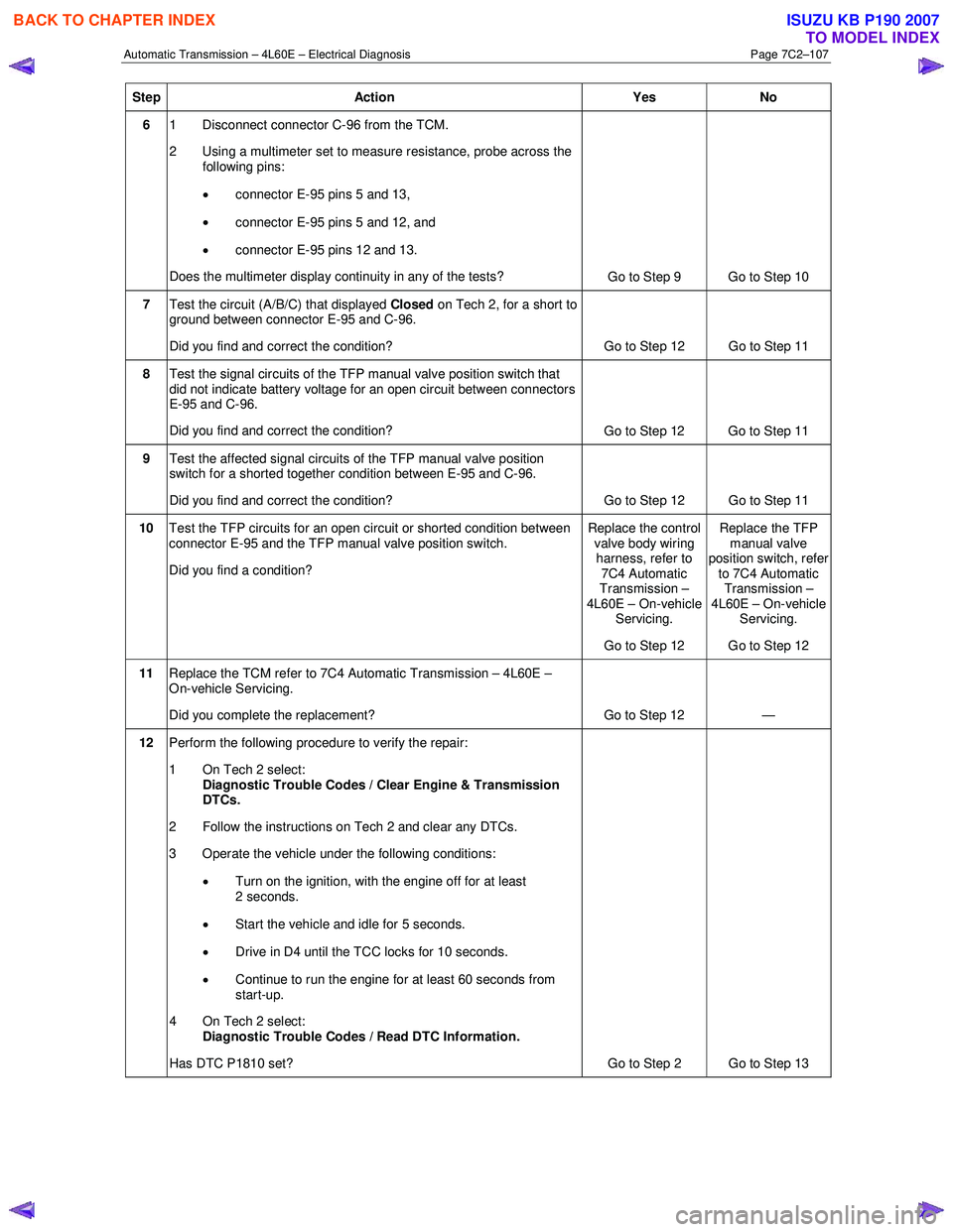
Step Action Yes No
6 1 Disconnect connector C-96 from the TCM.
2 Using a multimeter set to measure resistance, probe across the following pins:
• connector E-95 pins 5 and 13,
• connector E-95 pins 5 and 12, and
• connector E-95 pins 12 and 13.
Does the multimeter display continuity in any of the tests? Go to Step 9 Go to Step 10
7 Test the circuit (A/B/C) that displayed Closed on Tech 2, for a short to
ground between connector E-95 and C-96.
Did you find and correct the condition? Go to Step 12 Go to Step 11
8 Test the signal circuits of the TFP manual valve position switch that
did not indicate battery voltage for an open circuit between connectors
E-95 and C-96.
Did you find and correct the condition? Go to Step 12 Go to Step 11
9 Test the affected signal circuits of the TFP manual valve position
switch for a shorted together condition between E-95 and C-96.
Did you find and correct the condition? Go to Step 12 Go to Step 11
10 Test the TFP circuits for an open circuit or shorted condition between
connector E-95 and the TFP manual valve position switch.
Did you find a condition? Replace the control
valve body wiring harness, refer to
7C4 Automatic
Transmission –
4L60E – On-vehicle Servicing.
Go to Step 12 Replace the TFP
manual valve
position switch, refer
to 7C4 Automatic Transmission –
4L60E – On-vehicle Servicing.
Go to Step 12
11 Replace the TCM refer to 7C4 Automatic Transmission – 4L60E –
On-vehicle Servicing.
Did you complete the replacement? Go to Step 12 —
12 Perform the following procedure to verify the repair:
1 On Tech 2 select: Diagnostic Trouble Codes / Clear Engine & Transmission
DTCs.
2 Follow the instructions on Tech 2 and clear any DTCs.
3 Operate the vehicle under the following conditions:
• Turn on the ignition, with the engine off for at least
2 seconds.
• Start the vehicle and idle for 5 seconds.
• Drive in D4 until the TCC locks for 10 seconds.
• Continue to run the engine for at least 60 seconds from
start-up.
4 On Tech 2 select:
Diagnostic Trouble Codes / Read DTC Information.
Has DTC P1810 set? Go to Step 2 Go to Step 13
BACK TO CHAPTER INDEX
TO MODEL INDEX
ISUZU KB P190 2007
Page 3952 of 6020
Automatic Transmission – 4L60E – On-vehicle Servicing Page 7C4–39
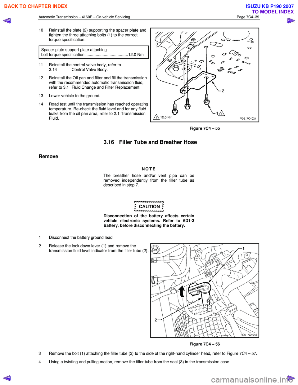
10 Reinstall the plate (2) supporting the spacer plate and
tighten the three attaching bolts (1) to the correct
torque specification.
Spacer plate support plate attaching
bolt torque specification ..................................... 12.0 Nm
11 Reinstall the control valve body, refer to 3.14 Control Valve Body.
12 Reinstall the Oil pan and filter and fill the transmission with the recommended automatic transmission fluid,
refer to 3.1 Fluid Change and Filter Replacement.
13 Lower vehicle to the ground.
14 Road test until the transmission has reached operating temperature. Re-check the fluid level and for any fluid
leaks from the oil pan area, refer to 2.1 Transmission
Fluid.
Figure 7C4 – 55
3.16 Filler Tube and Breather Hose
Remove
NOTE
The breather hose and/or vent pipe can be
removed independently from the filler tube as
described in step 7.
Disconnection of the battery affects certain
vehicle electronic systems. Refer to 6D1-3
Battery, before disconnecting the battery.
1 Disconnect the battery ground lead.
2 Release the lock down lever (1) and remove the transmission fluid level indicator from the filler tube (2).
Figure 7C4 – 56
3 Remove the bolt (1) attaching the filler tube (2) to the side of the right-hand cylinder head, refer to Figure 7C4 – 57.
4 Using a twisting and pulling motion, remove the filler tube from the seal (3) in the transmission case.
BACK TO CHAPTER INDEX
TO MODEL INDEX
ISUZU KB P190 2007
Page 4008 of 6020
7A2-42 TRANSMISSION CONTROL SYSTEM (AW30–40LE)
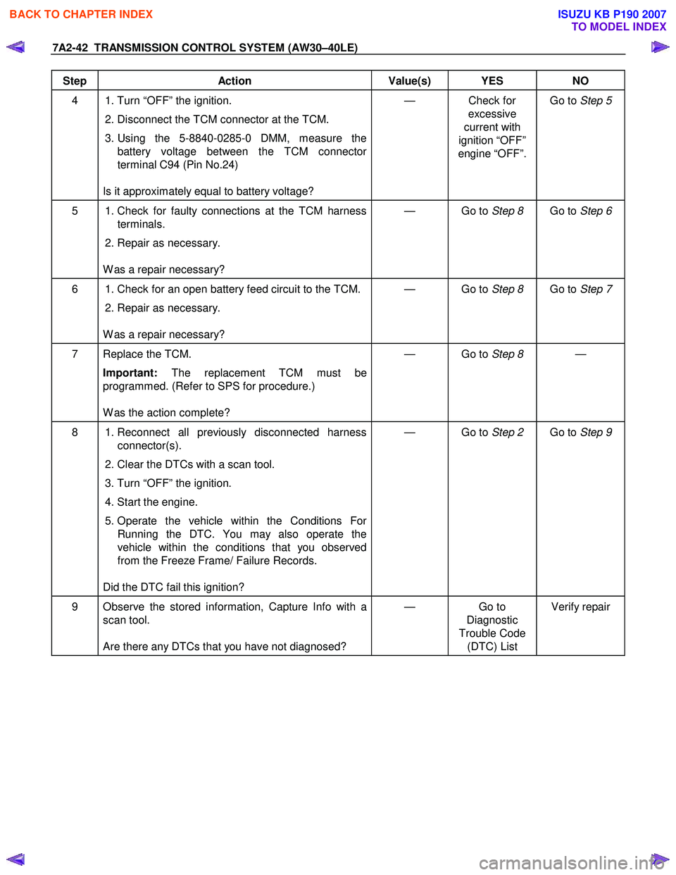
Step Action Value(s) YES NO
4 1. Turn “OFF” the ignition. 2. Disconnect the TCM connector at the TCM.
3. Using the 5-8840-0285-0 DMM, measure the battery voltage between the TCM connector
terminal C94 (Pin No.24)
Is it approximately equal to battery voltage? — Check for
excessive
current with
ignition “OFF”
engine “OFF”. Go to
Step 5
5 1. Check for faulty connections at the TCM harness
terminals.
2. Repair as necessary.
W as a repair necessary? — Go to
Step 8 Go to Step 6
6 1. Check for an open battery feed circuit to the TCM.
2. Repair as necessary.
W as a repair necessary? — Go to
Step 8 Go to Step 7
7 Replace the TCM.
Important: The replacement TCM must be
programmed. (Refer to SPS for procedure.)
W as the action complete? — Go to
Step 8 —
8 1. Reconnect all previously disconnected harness
connector(s).
2. Clear the DTCs with a scan tool.
3. Turn “OFF” the ignition.
4. Start the engine.
5. Operate the vehicle within the Conditions For Running the DTC. You may also operate the
vehicle within the conditions that you observed
from the Freeze Frame/ Failure Records.
Did the DTC fail this ignition? — Go to
Step 2 Go to Step 9
9 Observe the stored information, Capture Info with a
scan tool.
Are there any DTCs that you have not diagnosed? — Go
to
Diagnostic
Trouble Code (DTC) List Verify repair
BACK TO CHAPTER INDEX
TO MODEL INDEX
ISUZU KB P190 2007
Page 4111 of 6020
7A3-26 ON-VEHICLE SERVICE (AW30–40LE)
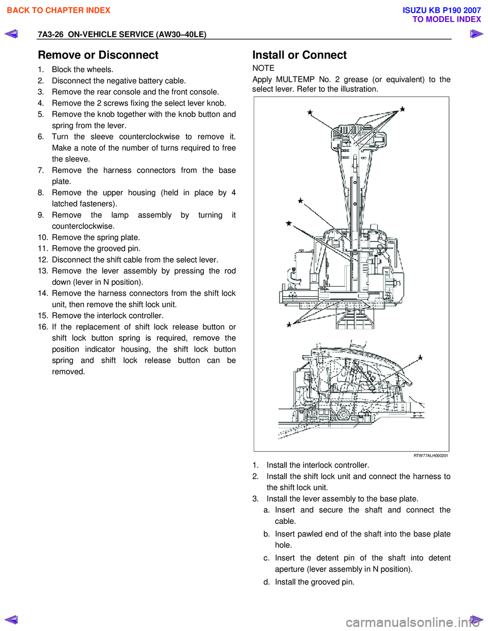
Remove or Disconnect
1. Block the wheels.
2. Disconnect the negative battery cable.
3. Remove the rear console and the front console.
4. Remove the 2 screws fixing the select lever knob.
5. Remove the knob together with the knob button and spring from the lever.
6. Turn the sleeve counterclockwise to remove it. Make a note of the number of turns required to free
the sleeve.
7. Remove the harness connectors from the base plate.
8. Remove the upper housing (held in place by 4 latched fasteners).
9. Remove the lamp assembly by turning it counterclockwise.
10. Remove the spring plate.
11. Remove the grooved pin.
12. Disconnect the shift cable from the select lever.
13. Remove the lever assembly by pressing the rod down (lever in N position).
14. Remove the harness connectors from the shift lock unit, then remove the shift lock unit.
15. Remove the interlock controller.
16. If the replacement of shift lock release button o
r
shift lock button spring is required, remove the
position indicator housing, the shift lock button
spring and shift lock release button can be
removed.
Install or Connect
NOTE
Apply MULTEMP No. 2 grease (or equivalent) to the
select lever. Refer to the illustration.
RTW 77ALH000201
1. Install the interlock controller.
2. Install the shift lock unit and connect the harness to the shift lock unit.
3. Install the lever assembly to the base plate. a. Insert and secure the shaft and connect the cable.
b. Insert pawled end of the shaft into the base plate hole.
c. Insert the detent pin of the shaft into detent aperture (lever assembly in N position).
d. Install the grooved pin.
BACK TO CHAPTER INDEX
TO MODEL INDEX
ISUZU KB P190 2007
Page 4117 of 6020
7A3-32 ON-VEHICLE SERVICE (AW30–40LE)
Shift Solenoid and Lock-Up Solenoid
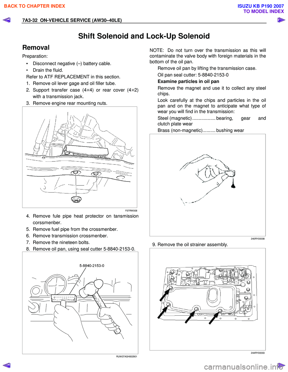
Removal
Preparation:
• Disconnect negative (–) battery cable.
• Drain the fluid.
Refer to ATF REPLACEMENT in this section.
1. Remove oil lever gage and oil filler tube.
2. Support transfer case (4
×4) or rear cover (4×2)
with a transmission jack.
3. Remove engine rear mounting nuts.
F07RW 008
4. Remove fule pipe heat protector on tansmission
corssmenber.
5. Remove fuel pipe from the crossmenber.
6. Remove transmission crossmenber.
7. Remove the nineteen bolts.
8. Remove oil pan, using seal cutter 5-8840-2153-0.
RUW 37ASH002901
NOTE: Do not turn over the transmission as this will
contaminate the valve body with foreign materials in the
bottom of the oil pan.
Remove oil pan by lifting the transmission case.
Oil pan seal cutter: 5-8840-2153-0
Examine particles in oil pan
Remove the magnet and use it to collect any steel
chips.
Look carefully at the chips and particles in the oil
pan and on the magnet to anticipate what type o
f
wear you will find in the transmission:
Steel (magnetic) .................. bearing, gear and
clutch plate wear
Brass (non-magnetic).......... bushing wear
240RY00008
9. Remove the oil strainer assembly.
244RY00003
BACK TO CHAPTER INDEX
TO MODEL INDEX
ISUZU KB P190 2007
Page 4119 of 6020
7A3-34 ON-VEHICLE SERVICE (AW30–40LE)
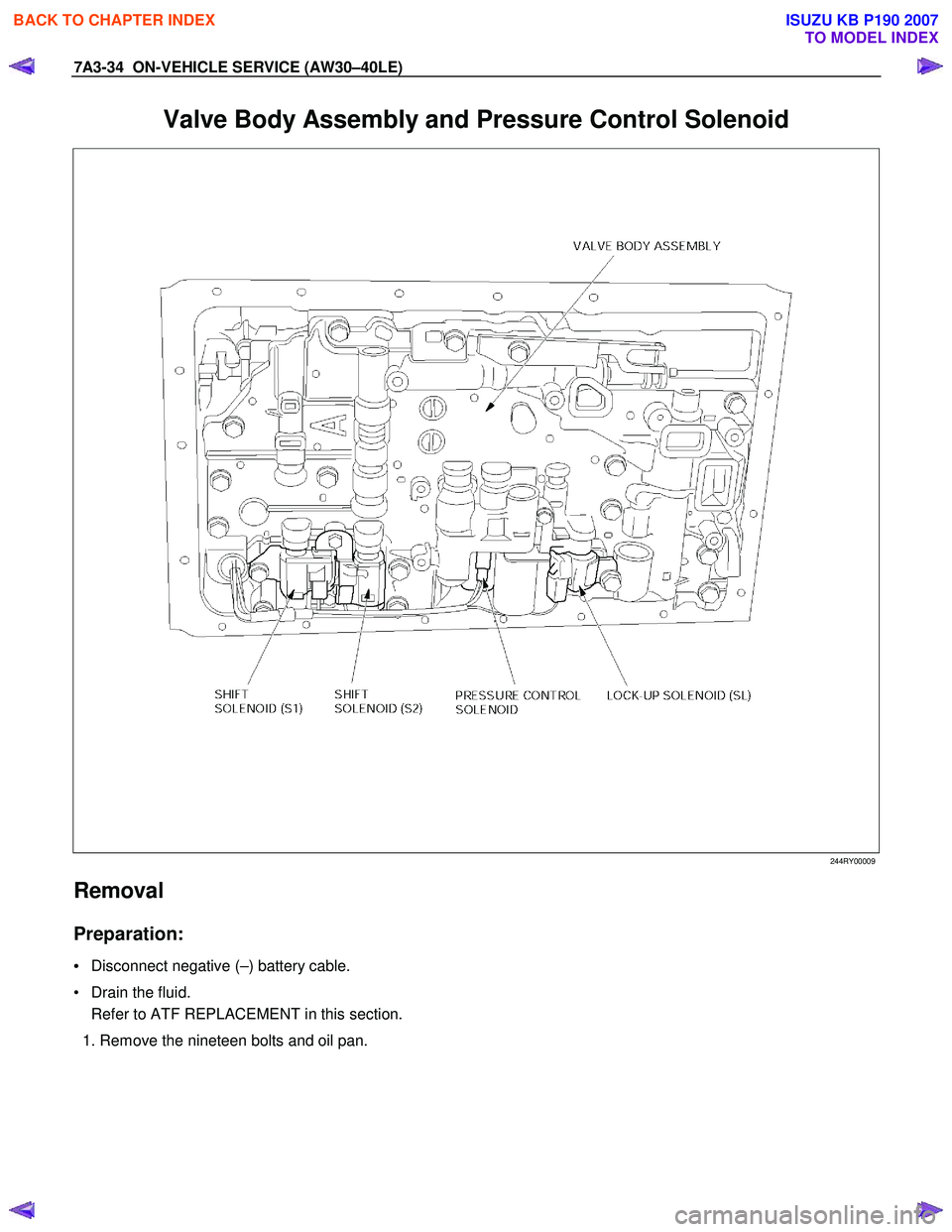
Valve Body Assembly and Pressure Control Solenoid
244RY00009
Removal
Preparation:
• Disconnect negative (–) battery cable.
• Drain the fluid. Refer to ATF REPLACEMENT in this section.
1. Remove the nineteen bolts and oil pan.
BACK TO CHAPTER INDEX
TO MODEL INDEX
ISUZU KB P190 2007
Page 4306 of 6020
7A2-22 TRANSMISSION CONTROL SYSTEM (JR405E)
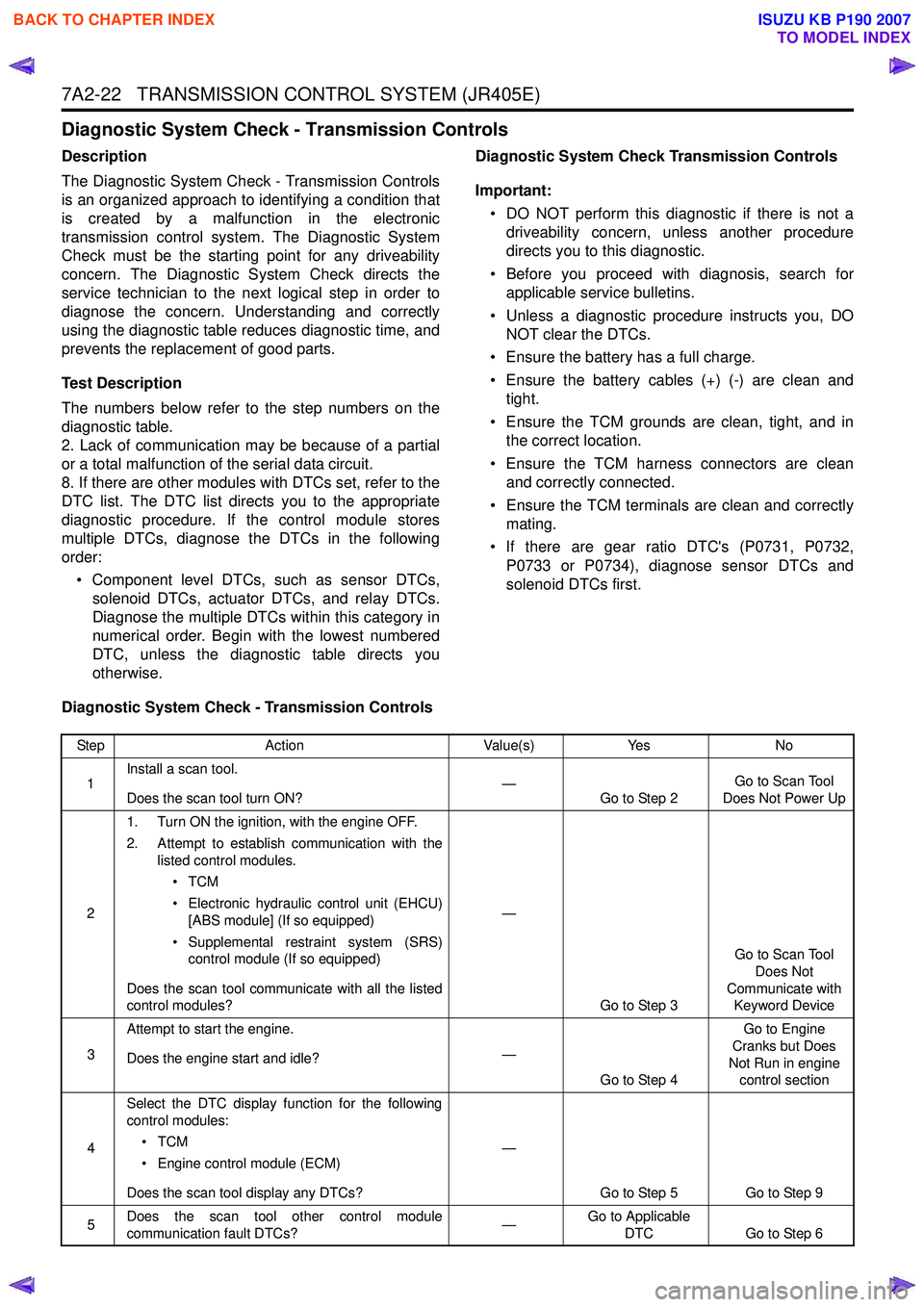
Diagnostic System Check - Transmission Controls
Description
The Diagnostic System Check - Transmission Controls
is an organized approach to identifying a condition that
is created by a malfunction in the electronic
transmission control system. The Diagnostic System
Check must be the starting point for any driveability
concern. The Diagnostic System Check directs the
service technician to the next logical step in order to
diagnose the concern. Understanding and correctly
using the diagnostic table reduces diagnostic time, and
prevents the replacement of good parts.
Test Description
The numbers below refer to the step numbers on the
diagnostic table.
2. Lack of communication may be because of a partial
or a total malfunction of the serial data circuit.
8. If there are other modules with DTCs set, refer to the
DTC list. The DTC list directs you to the appropriate
diagnostic procedure. If the control module stores
multiple DTCs, diagnose the DTCs in the following
order:
• Component level DTCs, such as sensor DTCs, solenoid DTCs, actuator DTCs, and relay DTCs.
Diagnose the multiple DTCs within this category in
numerical order. Begin with the lowest numbered
DTC, unless the diagnostic table directs you
otherwise. Diagnostic System Check Transmission Controls
Important: • DO NOT perform this diagnostic if there is not a driveability concern, unless another procedure
directs you to this diagnostic.
• Before you proceed with diagnosis, search for applicable service bulletins.
• Unless a diagnostic procedure instructs you, DO NOT clear the DTCs.
• Ensure the battery has a full charge.
• Ensure the battery cables (+) (-) are clean and tight.
• Ensure the TCM grounds are clean, tight, and in the correct location.
• Ensure the TCM harness connectors are clean and correctly connected.
• Ensure the TCM terminals are clean and correctly mating.
• If there are gear ratio DTC's (P0731, P0732, P0733 or P0734), diagnose sensor DTCs and
solenoid DTCs first.
Diagnostic System Check - Transmission Controls
Step Action Value(s)Yes No
1 Install a scan tool.
Does the scan tool turn ON? —
Go to Step 2 Go to Scan Tool
Does Not Power Up
2 1. Turn ON the ignition, with the engine OFF.
2. Attempt to establish communication with the listed control modules.
•TCM
• Electronic hydraulic control unit (EHCU) [ABS module] (If so equipped)
• Supplemental restraint system (SRS) control module (If so equipped)
Does the scan tool communicate with all the listed
control modules? —
Go to Step 3 Go to Scan Tool
Does Not
Communicate with Keyword Device
3 Attempt to start the engine.
Does the engine start and idle? —
Go to Step 4 Go to Engine
Cranks but Does
Not Run in engine control section
4 Select the DTC display function for the following
control modules:
•TCM
• Engine control module (ECM)
Does the scan tool display any DTCs? —
Go to Step 5 Go to Step 9
5 Does the scan tool other control module
communication fault DTCs? —Go to Applicable
DTC Go to Step 6
BACK TO CHAPTER INDEX
TO MODEL INDEX
ISUZU KB P190 2007
Page 4322 of 6020
7A2-38 TRANSMISSION CONTROL SYSTEM (JR405E)
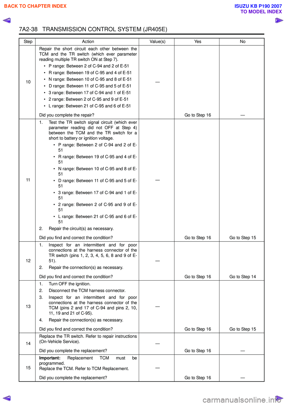
10Repair the short circuit each other between the
TCM and the TR switch (which ever parameter
reading multiple TR switch ON at Step 7).
• P range: Between 2 of C-94 and 2 of E-51
• R range: Between 19 of C-95 and 4 of E-51
• N range: Between 10 of C-95 and 8 of E-51
• D range: Between 11 of C-95 and 5 of E-51
• 3 range: Between 17 of C-94 and 1 of E-51
• 2 range: Between 2 of C-95 and 9 of E-51
• L range: Between 21 of C-95 and 6 of E-51
Did you complete the repair? —
Go to Step 16 —
11 1. Test the TR switch signal circuit (which ever
parameter reading did not OFF at Step 4)
between the TCM and the TR switch for a
short to battery or ignition voltage.
• P range: Between 2 of C-94 and 2 of E- 51
• R range: Between 19 of C-95 and 4 of E- 51
• N range: Between 10 of C-95 and 8 of E- 51
• D range: Between 11 of C-95 and 5 of E- 51
• 3 range: Between 17 of C-94 and 1 of E- 51
• 2 range: Between 2 of C-95 and 9 of E- 51
• L range: Between 21 of C-95 and 6 of E- 51
2. Repair the circuit(s) as necessary.
Did you find and correct the condition? —
Go to Step 16 Go to Step 15
12 1. Inspect for an intermittent and for poor
connections at the harness connector of the
TR switch (pins 1, 2, 3, 4, 5, 6, 8 and 9 of E-
51).
2. Repair the connection(s) as necessary.
Did you find and correct the condition? —
Go to Step 16 Go to Step 14
13 1. Turn OFF the ignition.
2. Disconnect the TCM harness connector.
3. Inspect for an intermittent and for poor connections at the harness connector of the
TCM (pins 2 and 17 of C-94 and pins 2, 10,
11, 19 and 21 of C-95).
4. Repair the connection(s) as necessary.
Did you find and correct the condition? —
Go to Step 16 Go to Step 15
14 Replace the TR switch. Refer to repair instructions
(On-Vehicle Service).
Did you complete the replacement? —
Go to Step 16 —
15 Important:
Replacement TCM must be
programmed.
Replace the TCM. Refer to TCM Replacement.
Did you complete the replacement? —
Go to Step 16 —
Step
Action Value(s)Yes No
BACK TO CHAPTER INDEX
TO MODEL INDEX
ISUZU KB P190 2007