2007 ISUZU KB P190 battery replacement
[x] Cancel search: battery replacementPage 1313 of 6020
Engine Control System (4JH1) 6E-279
Important:
Refer to Service Bulletins before service programming is
performed if the bulletins are listed along with the
calibration files.
Important:
Select Cancel if you receive a message stating that the
calibration selected is already the current calibration in
the scan tool and reprogramming with the same
download is not allowed.
14. Select Reprog.
15. The Transfer Data screen will appear until the progress bar reaches 100%.
Important:
The vehicle fitted with automatic transmission, Check
Trans lamp may blink while programming the ECM since
communication between the ECM and TCM is
interrupted. Clear DTC in any module afte
r
programming. 16. Select Close on the Programming Complete
screen.
17. Turn OFF the scan tool.
18. Disconnect the scan tool from the vehicle.
Accelerator Pedal Position (APP) Sensor
Replacement
Removal Procedure 1. Disconnect the negative battery cable.
2. Disconnect the APP sensor connector.
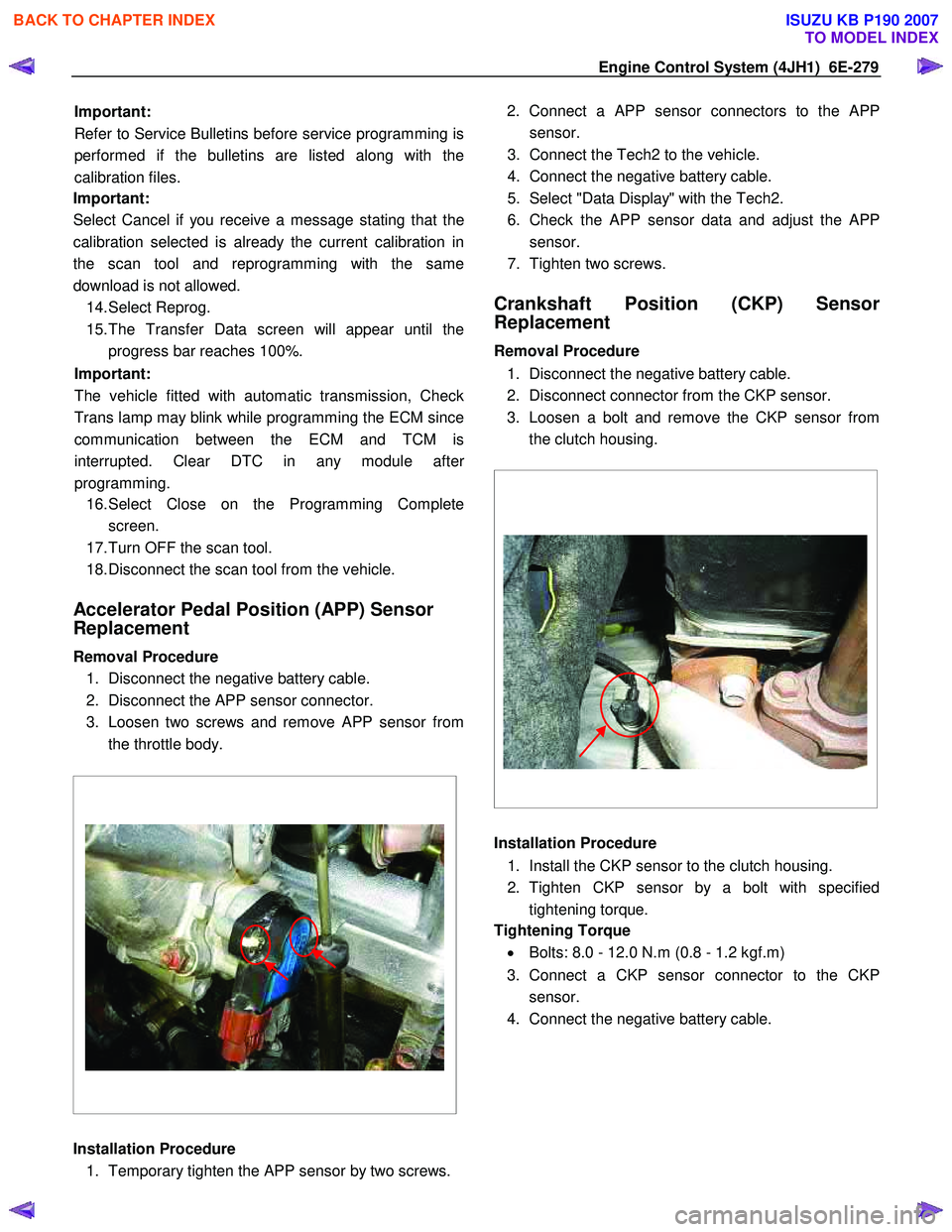
3. Loosen two screws and remove APP sensor from the throttle body.
Installation Procedure 1. Temporary tighten the APP sensor by two screws. 2. Connect a APP sensor connectors to the
APP
sensor.
3. Connect the Tech2 to the vehicle.
4. Connect the negative battery cable.
5. Select "Data Display" with the Tech2.
6. Check the APP sensor data and adjust the
APP
sensor.
7. Tighten two screws.
Crankshaft Position (CKP) Sensor
Replacement
Removal Procedure
1. Disconnect the negative battery cable.
2. Disconnect connector from the CKP sensor.
3. Loosen a bolt and remove the CKP sensor from the clutch housing.
Installation Procedure
1. Install the CKP sensor to the clutch housing.
2. Tighten CKP sensor by a bolt with specified tightening torque.
Tightening Torque
• Bolts: 8.0 - 12.0 N.m (0.8 - 1.2 kgf.m)
3. Connect a CKP sensor connector to the CKP sensor.
4. Connect the negative battery cable.
BACK TO CHAPTER INDEX
TO MODEL INDEX
ISUZU KB P190 2007
Page 1314 of 6020
6E-280 Engine Control System (4JH1)
EGR Solenid Valve Replacement
Removal Procedure 1. Disconenct the negative battery cable.
2. Disconnect a EGR solenoid valve harness connector.
3. Disconnect two hoses from the EGR solenoid valve.
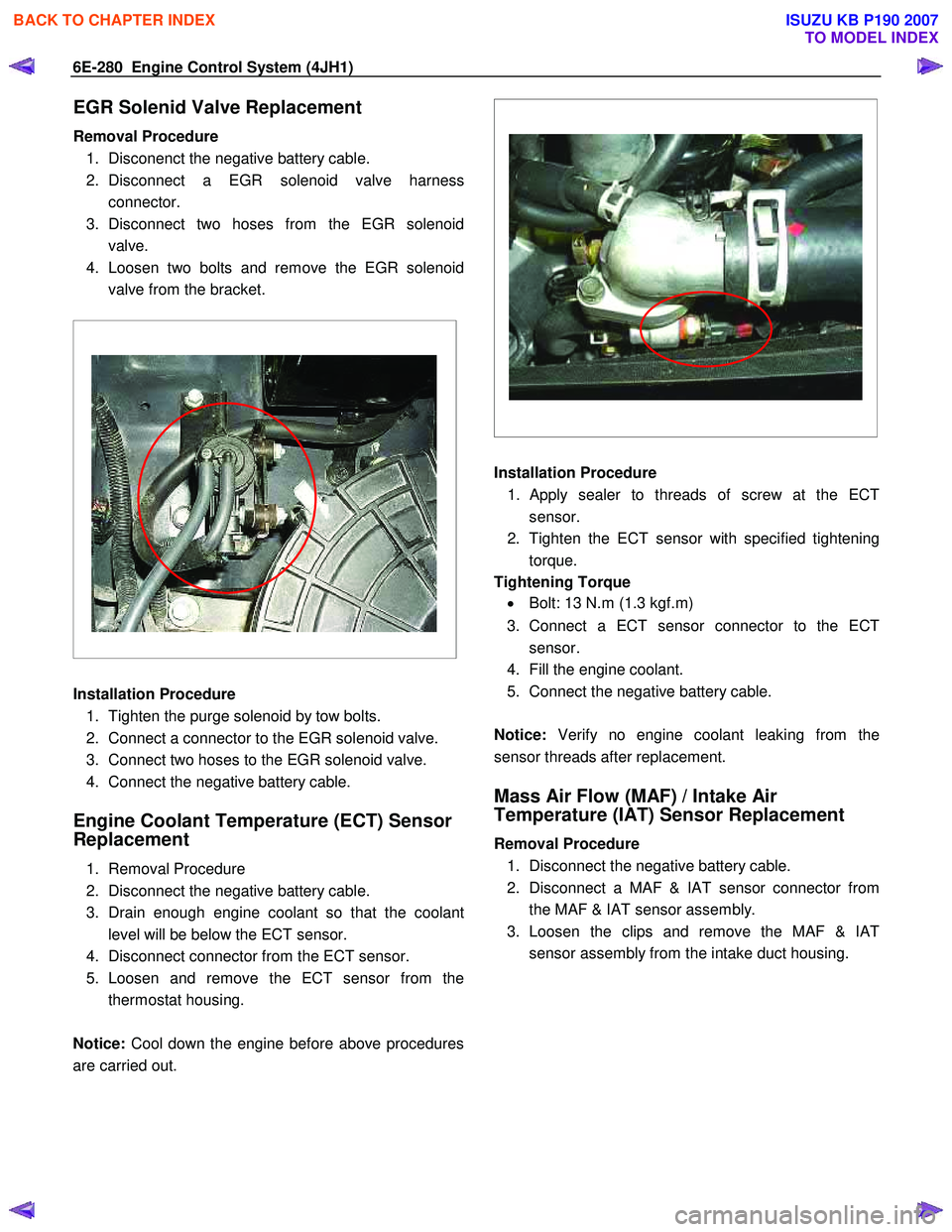
4. Loosen two bolts and remove the EGR solenoid valve from the bracket.
Installation Procedure
1. Tighten the purge solenoid by tow bolts.
2. Connect a connector to the EGR solenoid valve.
3. Connect two hoses to the EGR solenoid valve.
4. Connect the negative battery cable.
Engine Coolant Temperature (ECT) Sensor
Replacement
1. Removal Procedure
2. Disconnect the negative battery cable.
3. Drain enough engine coolant so that the coolant level will be below the ECT sensor.
4. Disconnect connector from the ECT sensor.
5. Loosen and remove the ECT sensor from the thermostat housing.
Notice: Cool down the engine before above procedures
are carried out.
Installation Procedure
1.
Apply sealer to threads of screw at the ECT
sensor.
2. Tighten the ECT sensor with specified tightening torque.
Tightening Torque • Bolt: 13 N.m (1.3 kgf.m)
3. Connect a ECT sensor connector to the ECT sensor.
4. Fill the engine coolant.
5. Connect the negative battery cable.
Notice: Verify no engine coolant leaking from the
sensor threads after replacement.
Mass Air Flow (MAF) / Intake Air
Temperature (IAT) Sensor Replacement
Removal Procedure
1. Disconnect the negative battery cable.
2. Disconnect a MAF & IAT sensor connector from the MAF & IAT sensor assembly.
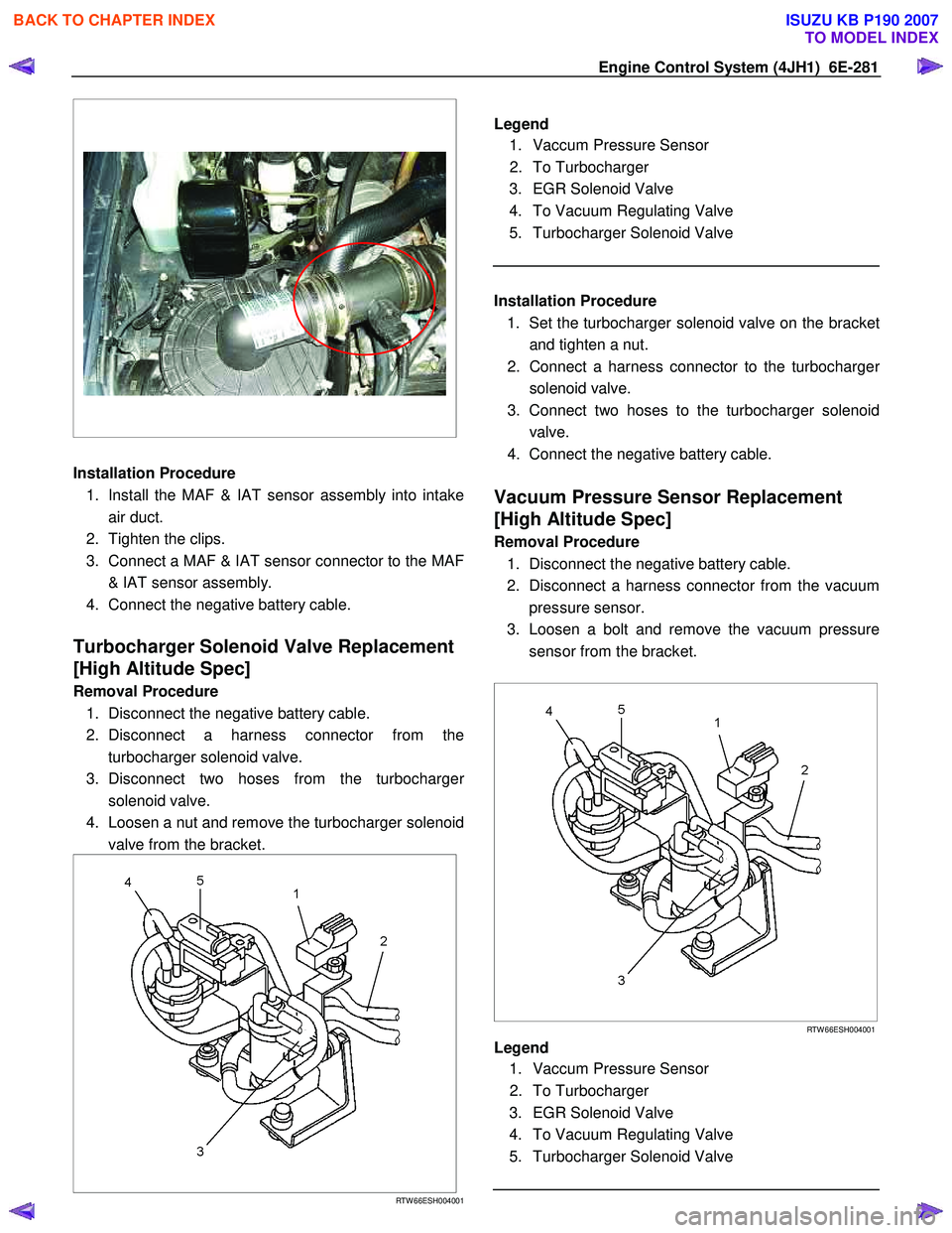
3. Loosen the clips and remove the MAF & IAT sensor assembly from the intake duct housing.
BACK TO CHAPTER INDEX
TO MODEL INDEX
ISUZU KB P190 2007
Page 1315 of 6020
Engine Control System (4JH1) 6E-281
Installation Procedure
1. Install the MAF & IAT sensor assembly into intake air duct.
2. Tighten the clips.
3. Connect a MAF & IAT sensor connector to the MAF & IAT sensor assembly.
4. Connect the negative battery cable.
Turbocharger Solenoid Valve Replacement
[High Altitude Spec]
Removal Procedure
1. Disconnect the negative battery cable.
2. Disconnect a harness connector from the turbocharger solenoid valve.
3. Disconnect two hoses from the turbocharge
r
solenoid valve.
4. Loosen a nut and remove the turbocharger solenoid valve from the bracket.
RTW 66ESH004001
Legend
1. Vaccum Pressure Sensor
2. To Turbocharger
3. EGR Solenoid Valve
4. To Vacuum Regulating Valve
5. Turbocharger Solenoid Valve
Installation Procedure
1. Set the turbocharger solenoid valve on the bracke
t
and tighten a nut.
2. Connect a harness connector to the turbocharge
r
solenoid valve.
3. Connect two hoses to the turbocharger solenoid valve.
4. Connect the negative battery cable.
Vacuum Pressure Sensor Replacement
[High Altitude Spec]
Removal Procedure
1. Disconnect the negative battery cable.
2. Disconnect a harness connector from the vacuum pressure sensor.
3. Loosen a bolt and remove the vacuum pressure sensor from the bracket.
RTW 66ESH004001
Legend
1. Vaccum Pressure Sensor
2. To Turbocharger
3. EGR Solenoid Valve
4. To Vacuum Regulating Valve
5. Turbocharger Solenoid Valve
BACK TO CHAPTER INDEX
TO MODEL INDEX
ISUZU KB P190 2007
Page 1316 of 6020

6E-282 Engine Control System (4JH1)
Installation Procedure 1. Set the vacuum pressure sensor on the bracket and tighten a bolt.
2. Connect a harness connector to the vacuum pressure sensor.
3. Connect the negative battery cable.
Vehicle Speed Sensor (VSS) Replacement
Removal Procedure
M/T & A/T (4W D) 1. Disconnect the negative battery cable.
2. Disconnect a harness connector from the vehicle speed sensor (VSS).
3. Remove the VSS from the transmission.
A/T (2W D)
1. Disconnect the negative battery cable.
2. Disconnect a harness connector from the vehicle speed sensor (VSS).
3. Loosen a bolt and remove the VSS from the transmission.
Installation Procedure
M/T & A/T (4W D) 1. Install the VSS at the transmission.
2. Connect a harness connector to the VSS.
3. Connect the negative battery cable.
M/T & A/T (4W D) 1. Set the VSS at the transmission and tighten a bolt.
2. Connect a harness connector to the VSS.
3. Connect the negative battery cable.
BACK TO CHAPTER INDEX
TO MODEL INDEX
ISUZU KB P190 2007
Page 1556 of 6020
FUEL SYSTEM (4JK1/4JJ1) 6C-15
The fuel system consists of many tiny holes and spaces
that allow the movement of fuel from one place to
another. These holes and spaces are milled to
extremely high precision. This is especially true of the
fuel injector.
The fuel injector is very sensitive to foreign material.
Foreign material will result in fuel system breakdown.
Exercise great care not to allow the entry of foreign
material into the fuel system or fuel injector during the
removal and installation procedure.
Note: To avoid electric shock;
Set the switch to the 'OFF' position and disconnect the
negative battery cable before checking or repairing the
fuel injector, wiring or/and connectors.
Removal
1. Remove the cylinder head cover.
Refer to the removal procedure for the cylinde
r
head cover in this manual.
Remove the attachment bolt of the engine oil gauge
guide tube.
2. Loosen the fuel injector clamp fixing bolts and
remove the fuel injector.
If the fuel injector is difficult to remove, use the remover. Use a screwdriver to force the fuel
injector clamp off the fuel injector.
Note: Do not remove the fuel injector sleeve.
Note: Cover the areas exposed during parts removal to
prevent the entry of foreign material into the fuel
system.
3. Mark each fuel injector with the number of the cylinder from which it was removed. Store the fuel
injector in a safe place. Position the fuel injector so
that the nozzle is protected.
Note: Do not tamper with the electromagnetic portion of
the fuel injector. Reduced electromagnetic function will
result in injector failure.
Note: After replacement of the fuel injector, perform the
following procedure.
• All fuel injectors are replaced:
Remove the fuel injector ID code label on the cylinder head cover.
• Any fuel injector(s) is replaced:
Black out the replaced cylinder of the fuel injecto
r
ID code on the fuel injector ID code label with a
marking pen or equivalent.
Installation
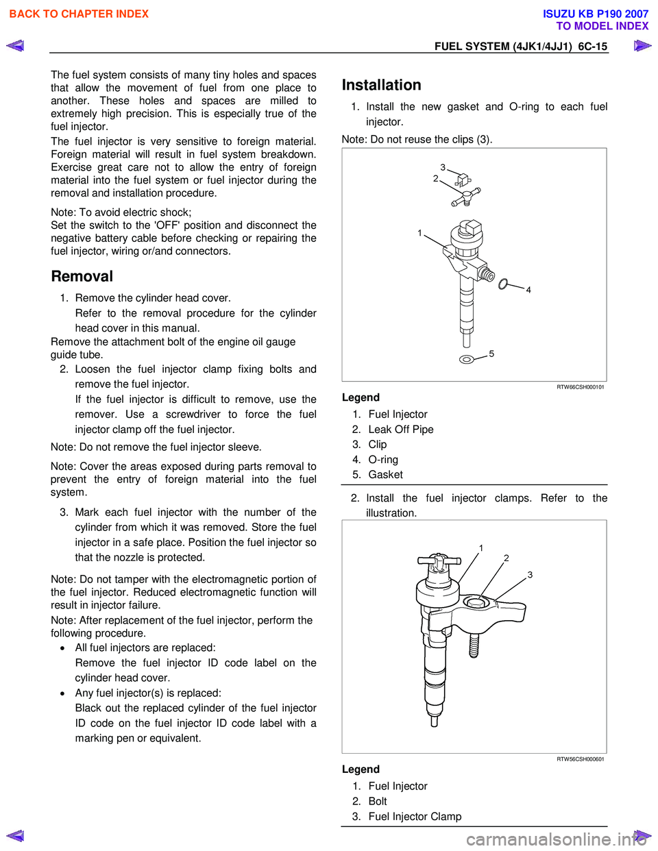
1. Install the new gasket and O-ring to each fuel
injector.
Note: Do not reuse the clips (3).
RTW 66CSH000101
Legend
1. Fuel Injector
2. Leak Off Pipe
3. Clip
4. O-ring
5. Gasket
2. Install the fuel injector clamps. Refer to the
illustration.
RTW 56CSH000601
Legend
1. Fuel Injector
2. Bolt
3. Fuel Injector Clamp
BACK TO CHAPTER INDEX
TO MODEL INDEX
ISUZU KB P190 2007
Page 1662 of 6020
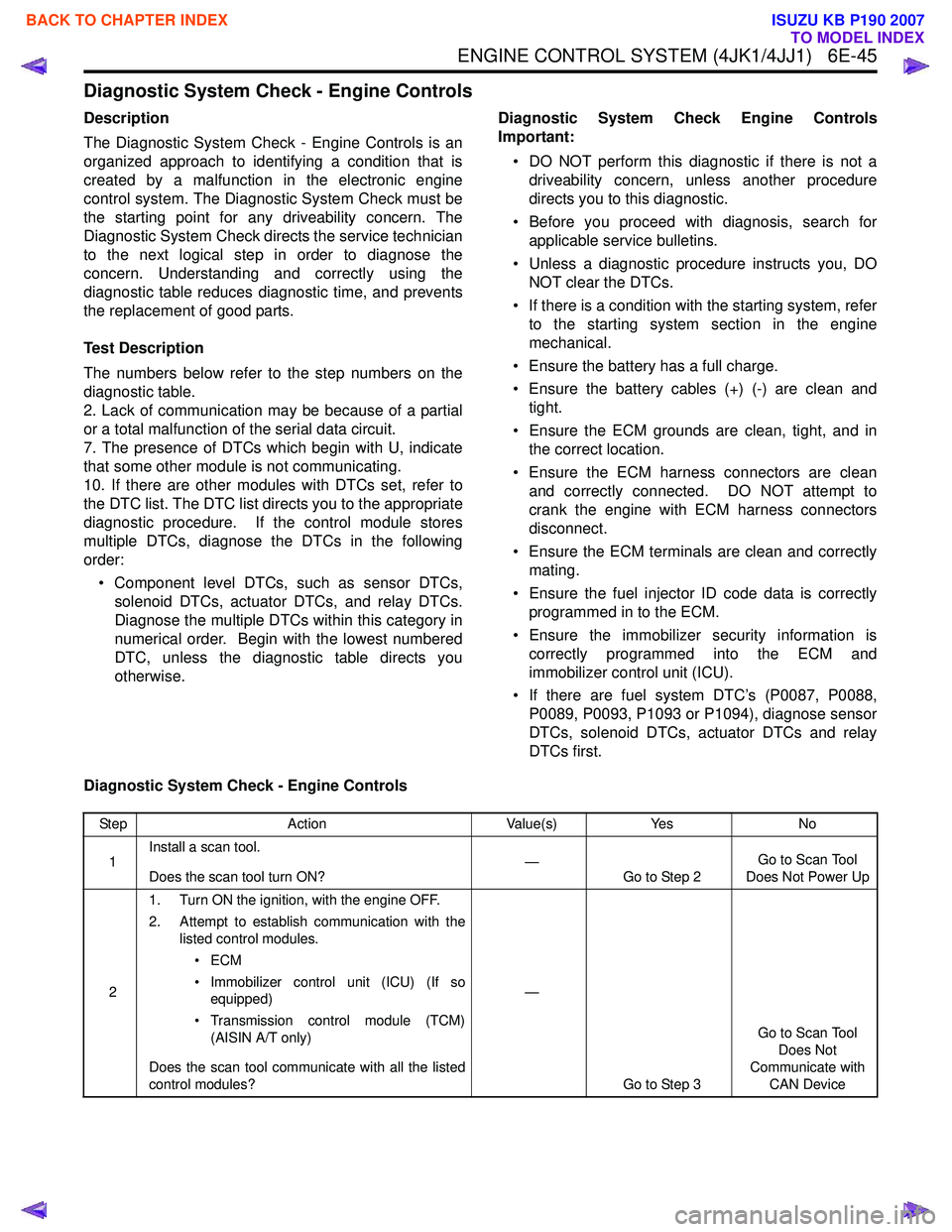
ENGINE CONTROL SYSTEM (4JK1/4JJ1) 6E-45
Diagnostic System Check - Engine Controls
Description
The Diagnostic System Check - Engine Controls is an
organized approach to identifying a condition that is
created by a malfunction in the electronic engine
control system. The Diagnostic System Check must be
the starting point for any driveability concern. The
Diagnostic System Check directs the service technician
to the next logical step in order to diagnose the
concern. Understanding and correctly using the
diagnostic table reduces diagnostic time, and prevents
the replacement of good parts.
Test Description
The numbers below refer to the step numbers on the
diagnostic table.
2. Lack of communication may be because of a partial
or a total malfunction of the serial data circuit.
7. The presence of DTCs which begin with U, indicate
that some other module is not communicating.
10. If there are other modules with DTCs set, refer to
the DTC list. The DTC list directs you to the appropriate
diagnostic procedure. If the control module stores
multiple DTCs, diagnose the DTCs in the following
order:
• Component level DTCs, such as sensor DTCs, solenoid DTCs, actuator DTCs, and relay DTCs.
Diagnose the multiple DTCs within this category in
numerical order. Begin with the lowest numbered
DTC, unless the diagnostic table directs you
otherwise. Diagnostic System Check Engine Controls
Important:
• DO NOT perform this diagnostic if there is not a driveability concern, unless another procedure
directs you to this diagnostic.
• Before you proceed with diagnosis, search for applicable service bulletins.
• Unless a diagnostic procedure instructs you, DO NOT clear the DTCs.
• If there is a condition with the starting system, refer to the starting system section in the engine
mechanical.
• Ensure the battery has a full charge.
• Ensure the battery cables (+) (-) are clean and tight.
• Ensure the ECM grounds are clean, tight, and in the correct location.
• Ensure the ECM harness connectors are clean and correctly connected. DO NOT attempt to
crank the engine with ECM harness connectors
disconnect.
• Ensure the ECM terminals are clean and correctly mating.
• Ensure the fuel injector ID code data is correctly programmed in to the ECM.
• Ensure the immobilizer security information is correctly programmed into the ECM and
immobilizer control unit (ICU).
• If there are fuel system DTC’s (P0087, P0088, P0089, P0093, P1093 or P1094), diagnose sensor
DTCs, solenoid DTCs, actuator DTCs and relay
DTCs first.
Diagnostic System Check - Engine Controls
Step Action Value(s)Yes No
1 Install a scan tool.
Does the scan tool turn ON? —
Go to Step 2 Go to Scan Tool
Does Not Power Up
2 1. Turn ON the ignition, with the engine OFF.
2. Attempt to establish communication with the listed control modules.
•ECM
• Immobilizer control unit (ICU) (If so equipped)
• Transmission control module (TCM) (AISIN A/T only)
Does the scan tool communicate with all the listed
control modules? —
Go to Step 3 Go to Scan Tool
Does Not
Communicate with CAN Device
BACK TO CHAPTER INDEX
TO MODEL INDEX
ISUZU KB P190 2007
Page 1678 of 6020
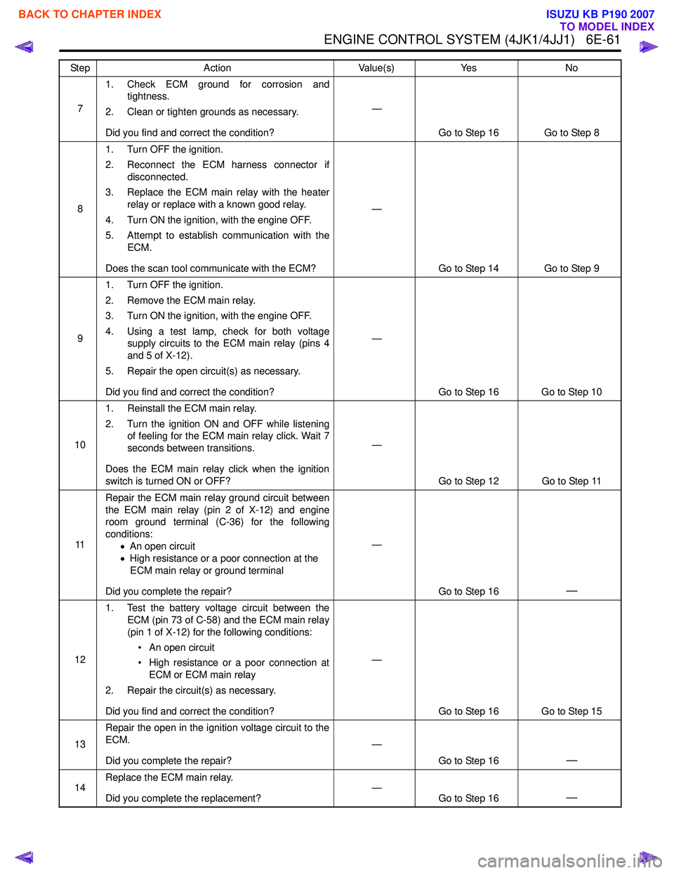
ENGINE CONTROL SYSTEM (4JK1/4JJ1) 6E-61
71. Check ECM ground for corrosion and
tightness.
2. Clean or tighten grounds as necessary.
Did you find and correct the condition? —
Go to Step 16 Go to Step 8
8 1. Turn OFF the ignition.
2. Reconnect the ECM harness connector if disconnected.
3. Replace the ECM main relay with the heater relay or replace with a known good relay.
4. Turn ON the ignition, with the engine OFF.
5. Attempt to establish communication with the ECM.
Does the scan tool communicate with the ECM? —
Go to Step 14 Go to Step 9
9 1. Turn OFF the ignition.
2. Remove the ECM main relay.
3. Turn ON the ignition, with the engine OFF.
4. Using a test lamp, check for both voltage supply circuits to the ECM main relay (pins 4
and 5 of X-12).
5. Repair the open circuit(s) as necessary.
Did you find and correct the condition? —
Go to Step 16 Go to Step 10
10 1. Reinstall the ECM main relay.
2. Turn the ignition ON and OFF while listening of feeling for the ECM main relay click. Wait 7
seconds between transitions.
Does the ECM main relay click when the ignition
switch is turned ON or OFF? —
Go to Step 12 Go to Step 11
11 Repair the ECM main relay ground circuit between
the ECM main relay (pin 2 of X-12) and engine
room ground terminal (C-36) for the following
conditions: •An open circuit
• High resistance or a poor connection at the
ECM main relay or ground terminal
Did you complete the repair? —
Go to Step 16
—
121. Test the battery voltage circuit between the
ECM (pin 73 of C-58) and the ECM main relay
(pin 1 of X-12) for the following conditions:
• An open circuit
• High resistance or a poor connection at ECM or ECM main relay
2. Repair the circuit(s) as necessary.
Did you find and correct the condition? —
Go to Step 16 Go to Step 15
13 Repair the open in the ignition voltage circuit to the
ECM.
Did you complete the repair? —
Go to Step 16
—
14Replace the ECM main relay.
Did you complete the replacement? —
Go to Step 16—
Step Action Value(s)Yes No
BACK TO CHAPTER INDEX
TO MODEL INDEX
ISUZU KB P190 2007
Page 1689 of 6020
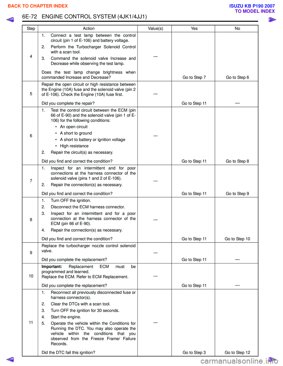
6E-72 ENGINE CONTROL SYSTEM (4JK1/4JJ1)
41. Connect a test lamp between the control
circuit (pin 1 of E-106) and battery voltage.
2. Perform the Turbocharger Solenoid Control with a scan tool.
3. Command the solenoid valve Increase and Decrease while observing the test lamp.
Does the test lamp change brightness when
commanded Increase and Decrease? —
Go to Step 7 Go to Step 6
5 Repair the open circuit or high resistance between
the Engine (10A) fuse and the solenoid valve (pin 2
of E-106). Check the Engine (10A) fuse first.
Did you complete the repair? —
Go to Step 11
—
61. Test the control circuit between the ECM (pin
66 of E-90) and the solenoid valve (pin 1 of E-
106) for the following conditions:
• An open circuit
• A short to ground
• A short to battery or ignition voltage
• High resistance
2. Repair the circuit(s) as necessary.
Did you find and correct the condition? —
Go to Step 11 Go to Step 8
7 1. Inspect for an intermittent and for poor
connections at the harness connector of the
solenoid valve (pins 1 and 2 of E-106).
2. Repair the connection(s) as necessary.
Did you find and correct the condition? —
Go to Step 11 Go to Step 9
8 1. Turn OFF the ignition.
2. Disconnect the ECM harness connector.
3. Inspect for an intermittent and for a poor connection at the harness connector of the
ECM (pin 66 of E-90).
4. Repair the connection(s) as necessary.
Did you find and correct the condition? —
Go to Step 11 Go to Step 10
9 Replace the turbocharger nozzle control solenoid
valve.
Did you complete the replacement? —
Go to Step 11
—
10Important:
Replacement ECM must be
programmed and learned.
Replace the ECM. Refer to ECM Replacement.
Did you complete the replacement? —
Go to Step 11
—
111. Reconnect all previously disconnected fuse or
harness connector(s).
2. Clear the DTCs with a scan tool.
3. Turn OFF the ignition for 30 seconds.
4. Start the engine.
5. Operate the vehicle within the Conditions for Running the DTC. You may also operate the
vehicle within the conditions that you
observed from the Freeze Frame/ Failure
Records.
Did the DTC fail this ignition? —
Go to Step 3 Go to Step 12
Step Action Value(s) Yes No
BACK TO CHAPTER INDEX
TO MODEL INDEX
ISUZU KB P190 2007