2007 ISUZU KB P190 Electrical
[x] Cancel search: ElectricalPage 1290 of 6020
6E-256 Engine Control System (4JH1)
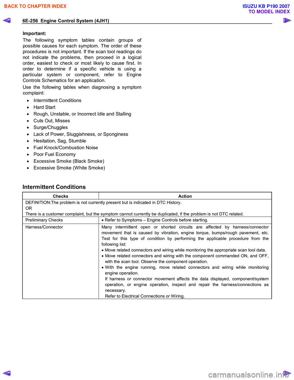
Important:
The following symptom tables contain groups o
f
possible causes for each symptom. The order of these
procedures is not important. If the scan tool readings do
not indicate the problems, then proceed in a logical
order, easiest to check or most likely to cause first. In
order to determine if a specific vehicle is using a
particular system or component, refer to Engine
Controls Schematics for an application.
Use the following tables when diagnosing a symptom
complaint:
• Intermittent Conditions
• Hard Start
• Rough, Unstable, or Incorrect Idle and Stalling
• Cuts Out, Misses
• Surge/Chuggles
• Lack of Power, Sluggishness, or Sponginess
• Hesitation, Sag, Stumble
• Fuel Knock/Combustion Noise
• Poor Fuel Economy
• Excessive Smoke (Black Smoke)
• Excessive Smoke (W hite Smoke)
Intermittent Conditions
Checks Action
DEFINITION:The problem is not currently present but is indicated in DTC History.
OR
There is a customer complaint, but the symptom cannot currently be duplicated, if the problem is not DTC related.
Preliminary Checks • Refer to Symptoms – Engine Controls before starting.
Harness/Connector Many intermittent open or shorted circuits are affected by harness/connector
movement that is caused by vibration, engine torque, bumps/rough pavement, etc.
Test for this type of condition by performing the applicable procedure from the
following list:
• Move related connectors and wiring while monitoring the appropriate scan tool data.
• Move related connectors and wiring with the component commanded ON, and OFF,
with the scan tool. Observe the component operation.
• W ith the engine running, move related connectors and wiring while monitoring
engine operation.
If harness or connector movement affects the data displayed, component/system
operation, or engine operation, inspect and repair the harness/connections as
necessary.
Refer to Electrical Connections or W iring.
BACK TO CHAPTER INDEX
TO MODEL INDEX
ISUZU KB P190 2007
Page 1291 of 6020

Engine Control System (4JH1) 6E-257
Checks Action
Electrical Connections or W iring Poor electrical connections, terminal tension or wiring problems cause most intermittent. To perform the following inspections:
• Inspect for poor mating of the connector halves, or terminals improperly seated in the
connector body.
• Inspect for improperly formed or damaged terminals. Test for poor terminal tension.
• Inspect for poor terminal to wire connections including terminals crimped over
insulation. This requires removing the terminal from the connector body.
• Inspect for corrosion/water intrusion. Pierced or damaged insulation can allow
moisture to enter the wiring. The conductor can corrode inside the insulation, with
little visible evidence. Look for swollen and stiff sections of wire in the suspect
circuits.
• Inspect for wires that are broken inside the insulation.
• Inspect the harness for pinched, cut or rubbed through wiring.
• Ensure that the wiring does not come in contact with hot exhaust components.
Control Module Power and Grounds
Component Power and Grounds Poor power or ground connections can cause widely varying symptoms.
• Test all control module power supply circuits. Many vehicles have multiple circuits
supplying power to the control module. Other components in the system may have
separate power supply circuits that may also need to be tested. Inspect connections
at the module/component connectors, fuses, and any intermediate connections
between the power source and the module/component. A test lamp or a DMM may
indicate that voltage is present, but neither tests the ability of the circuit to carry
sufficient current. Ensure that the circuit can carry the current necessary to operate
the component.
• Test all control module ground and system ground circuits. The control module may
have multiple ground circuits. Other components in the system may have separate
grounds that may also need to be tested. Inspect grounds for clean and tight
connections at the grounding point. Inspect the connections at the component and in
splice packs, where applicable. Ensure that the circuit can carry the current
necessary to operate the component.
Temperature Sensitivity • An intermittent condition may occur when a component/connection reaches normal
operating temperature. The condition may occur only when the
component/connection is cold, or only when the component/connection is hot.
• If the intermittent is related to heat, review the data for a relationship with the
following: - High ambient temperatures
- Under hood/engine generated heat
- Circuit generated heat due to a poor connection, or high electrical load
- Higher than normal load conditions, towing, etc.
• If the intermittent is related to cold, review the data for the following:
- Low ambient temperatures–In extremely low temperatures, ice may form in a connection or component. Test for water intrusion.
- The condition only occurs on a cold start.
- The condition goes away when the vehicle warms up.
• Information from the customer may help to determine if the trouble follows a pattern
that is temperature related.
BACK TO CHAPTER INDEX
TO MODEL INDEX
ISUZU KB P190 2007
Page 1292 of 6020
6E-258 Engine Control System (4JH1)
Checks Action
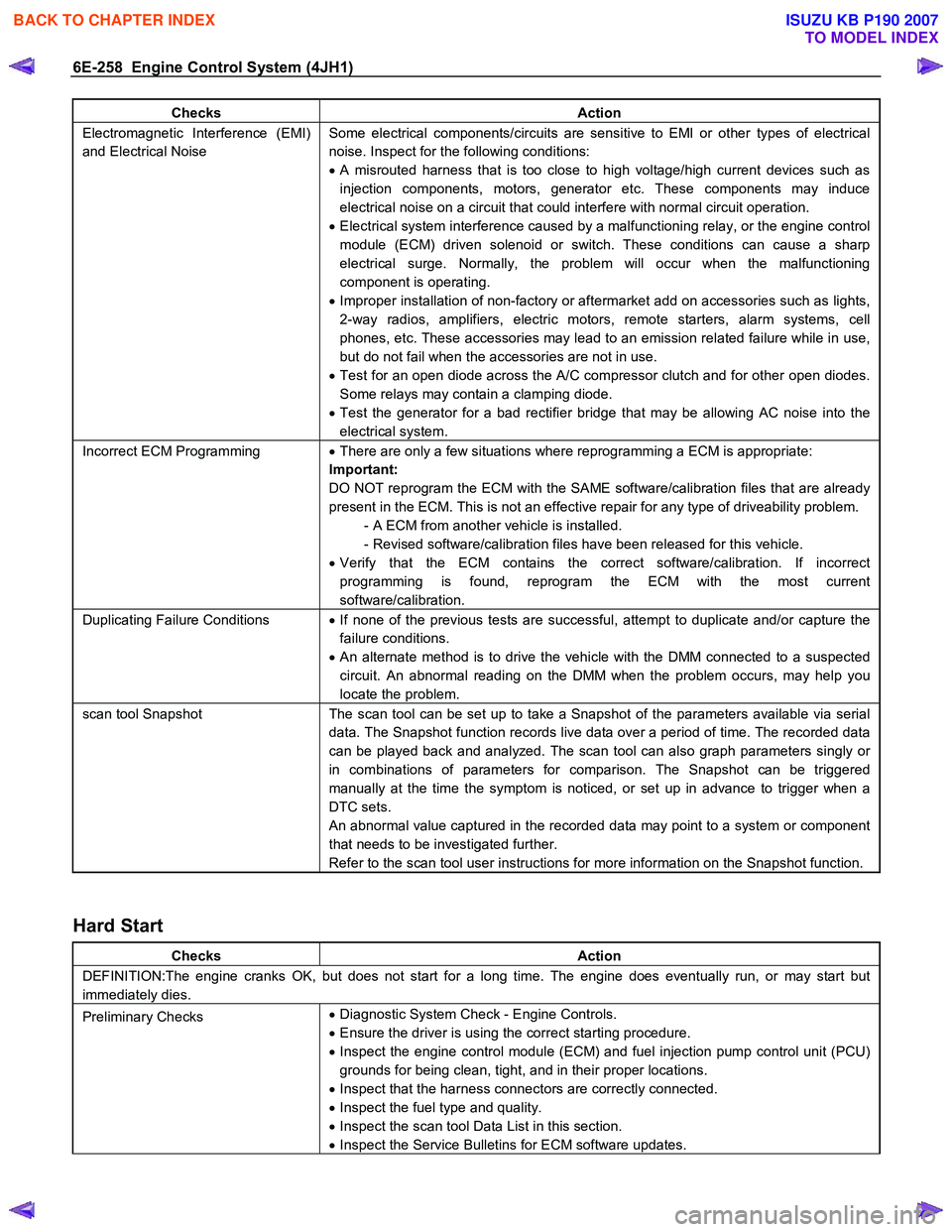
Electromagnetic Interference (EMI)
and Electrical Noise Some electrical components/circuits are sensitive to EMI or other types of electrical
noise. Inspect for the following conditions:
• A misrouted harness that is too close to high voltage/high current devices such as
injection components, motors, generator etc. These components may induce
electrical noise on a circuit that could interfere with normal circuit operation.
• Electrical system interference caused by a malfunctioning relay, or the engine control
module (ECM) driven solenoid or switch. These conditions can cause a sharp
electrical surge. Normally, the problem will occur when the malfunctioning
component is operating.
• Improper installation of non-factory or aftermarket add on accessories such as lights,
2-way radios, amplifiers, electric motors, remote starters, alarm systems, cell
phones, etc. These accessories may lead to an emission related failure while in use,
but do not fail when the accessories are not in use.
• Test for an open diode across the A/C compressor clutch and for other open diodes.
Some relays may contain a clamping diode.
• Test the generator for a bad rectifier bridge that may be allowing AC noise into the
electrical system.
Incorrect ECM Programming • There are only a few situations where reprogramming a ECM is appropriate:
Important:
DO NOT reprogram the ECM with the SAME software/calibration files that are already
present in the ECM. This is not an effective repair for any type of driveability problem. - A ECM from another vehicle is installed.
- Revised software/calibration files have been released for this vehicle.
• Verify that the ECM contains the correct software/calibration. If incorrect
programming is found, reprogram the ECM with the most current
software/calibration.
Duplicating Failure Conditions • If none of the previous tests are successful, attempt to duplicate and/or capture the
failure conditions.
• An alternate method is to drive the vehicle with the DMM connected to a suspected
circuit. An abnormal reading on the DMM when the problem occurs, may help you
locate the problem.
scan tool Snapshot The scan tool can be set up to take a Snapshot of the parameters available via serial
data. The Snapshot function records live data over a period of time. The recorded data
can be played back and analyzed. The scan tool can also graph parameters singly or
in combinations of parameters for comparison. The Snapshot can be triggered
manually at the time the symptom is noticed, or set up in advance to trigger when a
DTC sets.
An abnormal value captured in the recorded data may point to a system or component
that needs to be investigated further.
Refer to the scan tool user instructions for more information on the Snapshot function.
Hard Start
Checks Action
DEFINITION:The engine cranks OK, but does not start for a long time. The engine does eventually run, or may start but
immediately dies.
Preliminary Checks •
Diagnostic System Check - Engine Controls.
• Ensure the driver is using the correct starting procedure.
• Inspect the engine control module (ECM) and fuel injection pump control unit (PCU)
grounds for being clean, tight, and in their proper locations.
• Inspect that the harness connectors are correctly connected.
• Inspect the fuel type and quality.
• Inspect the scan tool Data List in this section.
• Inspect the Service Bulletins for ECM software updates.
BACK TO CHAPTER INDEX
TO MODEL INDEX
ISUZU KB P190 2007
Page 1294 of 6020
6E-260 Engine Control System (4JH1)
Checks Action
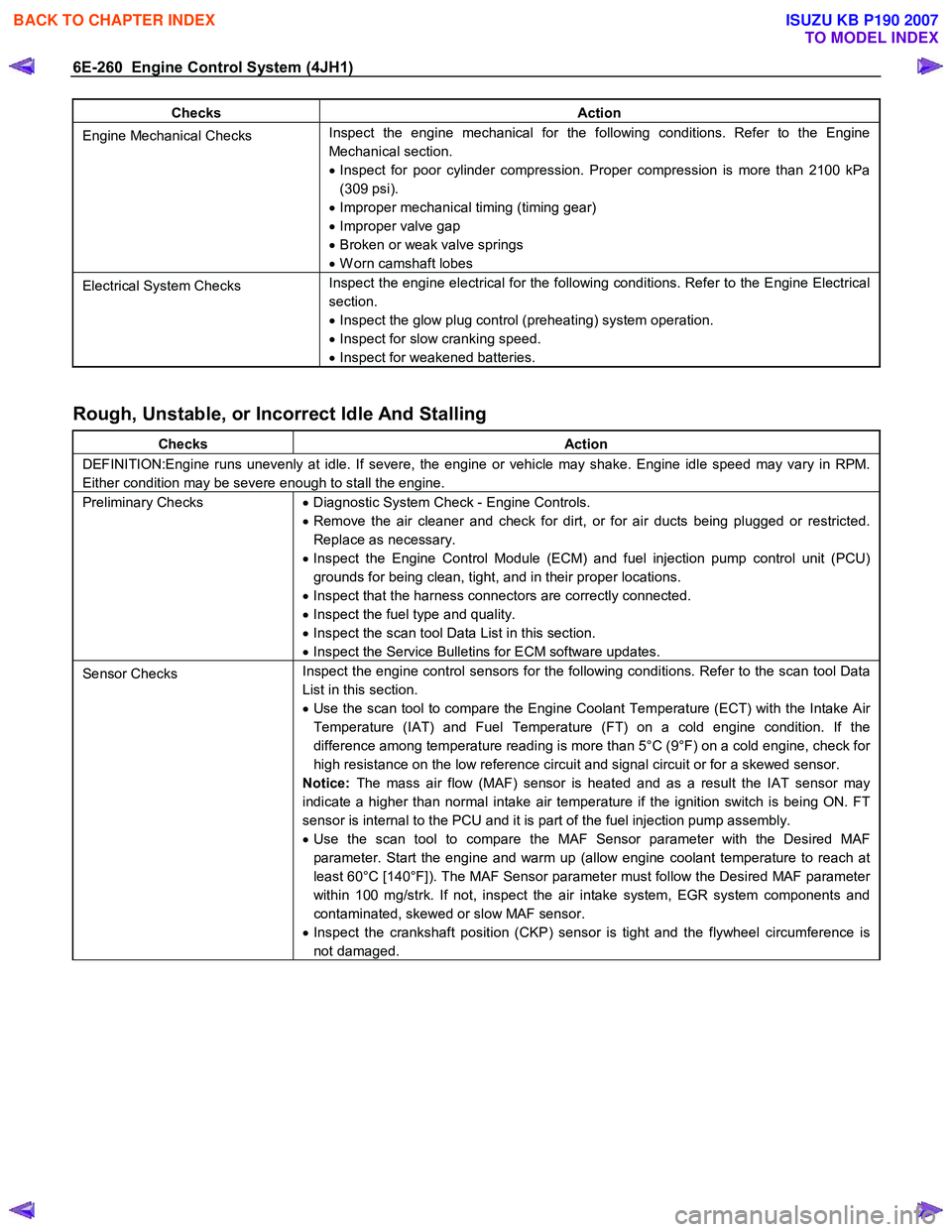
Engine Mechanical Checks Inspect the engine mechanical for the following conditions. Refer to the Engine
Mechanical section.
• Inspect for poor cylinder compression. Proper compression is more than 2100 kPa
(309 psi).
• Improper mechanical timing (timing gear)
• Improper valve gap
• Broken or weak valve springs
• W orn camshaft lobes
Electrical System Checks Inspect the engine electrical for the following conditions. Refer to the Engine Electrical
section.
• Inspect the glow plug control (preheating) system operation.
• Inspect for slow cranking speed.
• Inspect for weakened batteries.
Rough, Unstable, or Incorrect Idle And Stalling
Checks Action
DEFINITION:Engine runs unevenly at idle. If severe, the engine or vehicle may shake. Engine idle speed may vary in RPM.
Either condition may be severe enough to stall the engine.
Preliminary Checks • Diagnostic System Check - Engine Controls.
• Remove the air cleaner and check for dirt, or for air ducts being plugged or restricted.
Replace as necessary.
• Inspect the Engine Control Module (ECM) and fuel injection pump control unit (PCU)
grounds for being clean, tight, and in their proper locations.
• Inspect that the harness connectors are correctly connected.
• Inspect the fuel type and quality.
• Inspect the scan tool Data List in this section.
• Inspect the Service Bulletins for ECM software updates.
Sensor Checks Inspect the engine control sensors for the following conditions. Refer to the scan tool Data
List in this section.
• Use the scan tool to compare the Engine Coolant Temperature (ECT) with the Intake Air
Temperature (IAT) and Fuel Temperature (FT) on a cold engine condition. If the
difference among temperature reading is more than 5°C (9°F) on a cold engine, check for
high resistance on the low reference circuit and signal circuit or for a skewed sensor.
Notice: The mass air flow (MAF) sensor is heated and as a result the IAT sensor may
indicate a higher than normal intake air temperature if the ignition switch is being ON. FT
sensor is internal to the PCU and it is part of the fuel injection pump assembly.
• Use the scan tool to compare the MAF Sensor parameter with the Desired MAF
parameter. Start the engine and warm up (allow engine coolant temperature to reach at
least 60°C [140°F]). The MAF Sensor parameter must follow the Desired MAF parameter
within 100 mg/strk. If not, inspect the air intake system, EGR system components and
contaminated, skewed or slow MAF sensor.
• Inspect the crankshaft position (CKP) sensor is tight and the flywheel circumference is
not damaged.
BACK TO CHAPTER INDEX
TO MODEL INDEX
ISUZU KB P190 2007
Page 1308 of 6020
6E-274 Engine Control System (4JH1)
Checks Action
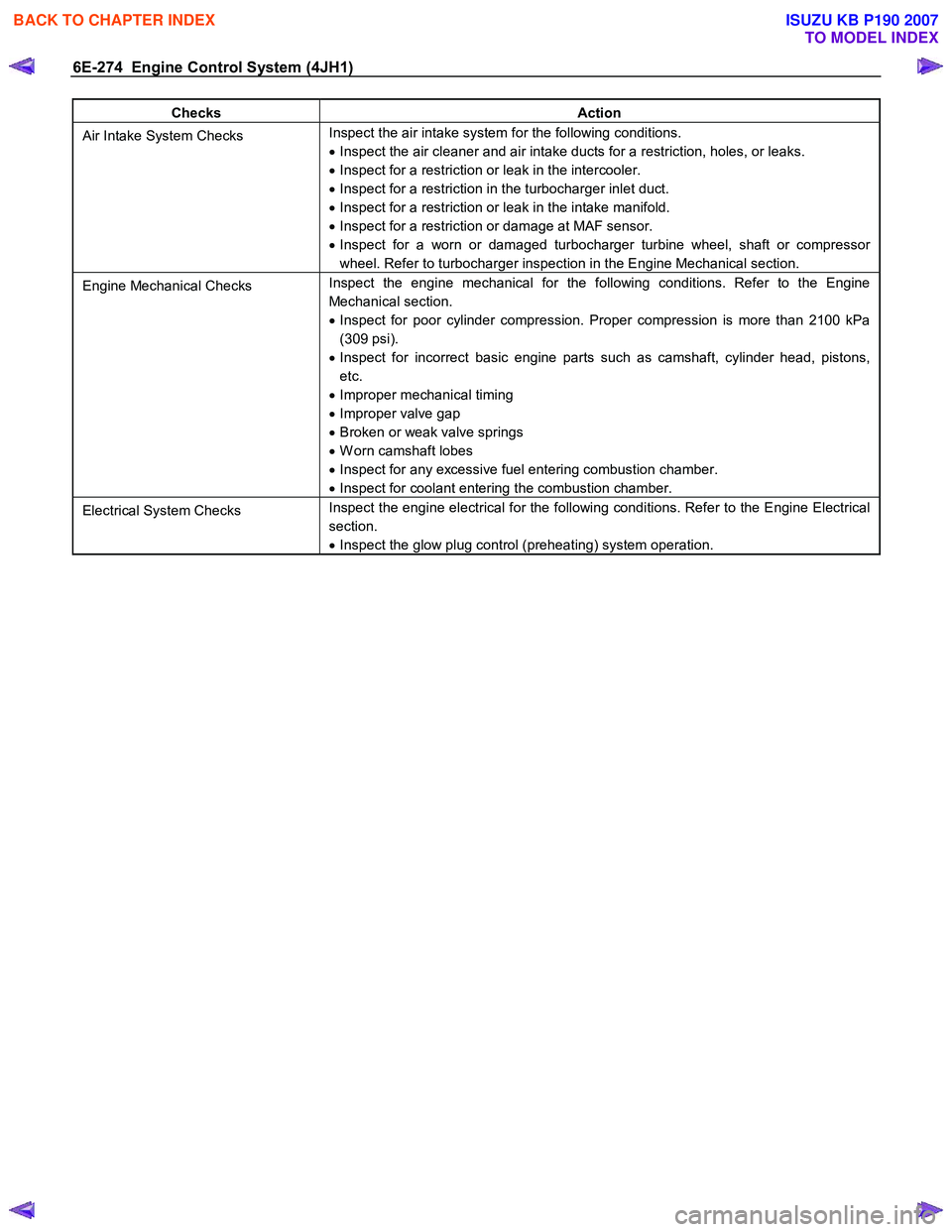
Air Intake System Checks Inspect the air intake system for the following conditions.
• Inspect the air cleaner and air intake ducts for a restriction, holes, or leaks.
• Inspect for a restriction or leak in the intercooler.
• Inspect for a restriction in the turbocharger inlet duct.
• Inspect for a restriction or leak in the intake manifold.
• Inspect for a restriction or damage at MAF sensor.
• Inspect for a worn or damaged turbocharger turbine wheel, shaft or compressor
wheel. Refer to turbocharger inspection in the Engine Mechanical section.
Engine Mechanical Checks Inspect the engine mechanical for the following conditions. Refer to the Engine
Mechanical section.
• Inspect for poor cylinder compression. Proper compression is more than 2100 kPa
(309 psi).
• Inspect for incorrect basic engine parts such as camshaft, cylinder head, pistons,
etc.
• Improper mechanical timing
• Improper valve gap
• Broken or weak valve springs
• W orn camshaft lobes
• Inspect for any excessive fuel entering combustion chamber.
• Inspect for coolant entering the combustion chamber.
Electrical System Checks Inspect the engine electrical for the following conditions. Refer to the Engine Electrical
section.
• Inspect the glow plug control (preheating) system operation.
BACK TO CHAPTER INDEX
TO MODEL INDEX
ISUZU KB P190 2007
Page 1310 of 6020
6E-276 Engine Control System (4JH1)
1. Connect the scan tool to the vehicle DLC, with theengine and the scan tool OFF.
2. Turn ON the scan tool.
3. Select Diagnostic > appropriate vehicle identification > Powertrain > 4JH1-TC >
Programming > Program VIN.
4. Input correct VIN reading from stamped VIN o
r
affixed VIN plate on the vehicle.
Select Lock ECU and lock the programmed VIN.
Service Programming System (SPS)
Description
The service programming system (SPS) allows a
technician to program a control module through the data
link connector (DLC). The information transfer circuit that
is used at the DLC is the same serial data circuit used be
the scan tool for retrieving diagnostic trouble codes
(DTCs), displaying data, clearing DTCs etc. This
procedure offers the ability to install software/calibrations
matched to a particular vehicle.
Most control modules have two types of memory. The
software/calibrations reside in the flash memory. The two
types of memory are listed below: • Electrically Erasable Programmable Read Onl
y
Memory (EEPROM).
This type of memory allows selected portions o
f
memory to be programmed while other portions
remain unchanged.
Certain learned values reside in the EEPROM, such as:
- The vehicle identification number (VIN)
- The software/calibrations identification numbers
- The control module security information
• Flash Read Only Memory-Flash Memory
Flash memory has increased memory storage capacity. During programming, all information within
this type of memory is erased, and then replaced
with entirely new information.
Service Programming Methods
The two methods of programming an engine control
module (ECM) are listed below: • Remote Programming
• Pass Thru Programming
For information on programming an ECM using one o
f
the methods listed above, refer to Service Programming
System (SPS) (Remote Procedure) or Service
Programming System (SPS) (Pass-Thru Procedure).
Before Programming a Control Module
Important:
DO NOT program an existing ECM with the identical
software/calibration package. This procedure is not a
short cut to correct the driveability condition. This is an
ineffective repair. An ECM should only be programmed
when the following occurs: • W hen a service procedure instructs you to replace
the ECM. W hen the ECM from another vehicle is
installed, VIN must be changed. And change
vehicle information as necessary such as type o
f
transmission.
• An updated software/calibrations is released.
Ensure that the following conditions are met before
programming an ECM: • The scan tool PCMCIA card is programmed with
the latest software.
• The TIS 2000 is installed with the latest software.
• The hardware key is plugged into the compute
r
port.
• Vehicle system voltage:
- There are no charging system concerns. All charging system concerns must be repaired
before programming the ECM.
- The battery voltage is greater than 12 volts bu
t
less than 16 volts. The battery must be fully
charged before programming the ECM.
-
A battery charger is NOT connected to the
vehicles battery. Incorrect system voltage o
r
voltage fluctuations from a battery charger may
cause programming failure or ECM damage.
- Turn OFF or disable any system that may put a load on the vehicles battery. Turn OFF o
r
disable systems such as:
◊ Heating, ventilation, and air conditioning
(HVAC) systems
◊ Headlights
◊ Room lights
◊ Accessory equipment
• The ignition switch is in the proper position. The
scan tool prompts you to turn ON the ignition, with
the engine OFF. DO NOT change the position o
f
the ignition switch during the programming
procedure unless instructed to do so.
• All tool connections are secure:
- The RS-232 cable
- The connection at the DLC
- The voltage supply circuits
BACK TO CHAPTER INDEX
TO MODEL INDEX
ISUZU KB P190 2007
Page 1317 of 6020
Engine Control System (4JH1) 6E-283
Description And Operation
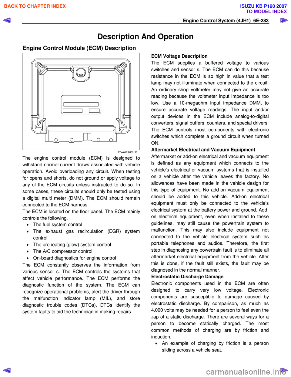
Engine Control Module (ECM) Description
RTW 66ESH001201
The engine control module (ECM) is designed to
withstand normal current draws associated with vehicle
operation. Avoid overloading any circuit. W hen testing
for opens and shorts, do not ground or apply voltage to
any of the ECM circuits unless instructed to do so. In
some cases, these circuits should only be tested using
a digital multi meter (DMM). The ECM should remain
connected to the ECM harness.
The ECM is located on the floor panel. The ECM mainl
y
controls the following.
• The fuel system control
• The exhaust gas recirculation (EGR) system
control
• The preheating (glow) system control
• The A/C compressor control
• On-board diagnostics for engine control
The ECM constantly observes the information from
various sensor s. The ECM controls the systems that
affect vehicle performance. The ECM performs the
diagnostic function of the system. The ECM can
recognize operational problems, alert the driver through
the malfunction indicator lamp (MIL), and store
diagnostic trouble codes (DTCs). DTCs identify the
system faults to aid the technician in making repairs.
ECM Voltage Description
The ECM supplies a buffered voltage to various
switches and sensor s. The ECM can do this because
resistance in the ECM is so high in value that a test
lamp may not illuminate when connected to the circuit.
An ordinary shop voltmeter may not give an accurate
reading because the voltmeter input impedance is too
low. Use a 10-megaohm input impedance DMM, to
ensure accurate voltage readings. The input and/o
r
output devices in the ECM include analog-to-digital
converters, signal buffers, counters, and special drivers.
The ECM controls most components with electronic
switches which complete a ground circuit when turned
ON.
Aftermarket Electrical and Vacuum Equipment
Aftermarket or add-on electrical and vacuum equipment
is defined as any equipment which connects to the
vehicle's electrical or vacuum systems that is installed
on a vehicle after the vehicle leaves the factory. No
allowances have been made in the vehicle design fo
r
this type of equipment. No add-on vacuum equipment
should be added to this vehicle. Add-on electrical
equipment must only be connected to the vehicle's
electrical system at the battery power and ground. Add-
on electrical equipment, even when installed to these
guidelines, may still cause the powertrain system to
malfunction. This may also include equipment not
connected to the vehicle electrical system such as
portable telephones and audios. Therefore, the first
step in diagnosing any powertrain fault is to eliminate all
aftermarket electrical equipment from the vehicle. Afte
r
this is done, if the fault still exists, the fault may be
diagnosed in the normal manner.
Electrostatic Discharge Damage
Electronic components used in the ECM are often
designed to carry very low voltage. Electronic
components are susceptible to damage caused b
y
electrostatic discharge. By comparison, as much as
4,000 volts may be needed for a person to feel even the
zap of a static discharge. There are several ways for a
person to become statically charged. The most
common methods of charging are by friction and
induction. •
An example of charging by friction is a person
sliding across a vehicle seat.
BACK TO CHAPTER INDEX
TO MODEL INDEX
ISUZU KB P190 2007
Page 1360 of 6020
PAGE
Section 6A Engine Mechanical .................................................................................... 1361
Section 6B Engine Cooling .......................................................................................... 1524
Section 6C Fuel System ............................................................................................... 1542
Section 6D Engine Electrical ....................................................................................... 1589
Section 6E Engine Control System ............................................................................ 1618
Section 6F Exhaust System ........................................................................................ 1986
Section 6H Engine Speed Control System ................................................................ 1998
SECTION 6
ENGINE
TA BLE OF CONTENTS
ENGINE 6
4JK
1/4J J1 MODELS
BACK TO CHAPTER INDEX
TO MODEL INDEX
ISUZU KB P190 2007