2007 ISUZU KB P190 Electrical
[x] Cancel search: ElectricalPage 1363 of 6020
ENGINE MECHANICAL (4JK1/4JJ1) 6A-3
ISUZU DIESEL ENGINE (4JK1/4JJ1)
Service Precautions
Matters that require attention in terms of
maintenance
To prevent damage to the engine and ensure reliabilit
y
of its performance, pay attention to the following in
maintaining the engine:
• W hen lifting up or supporting the engine, do not
apply a jack on the oil pan.
W hen taking down the engine on the ground, do not make the bearing surface of the oil pan touch
the ground directly. Use a wooden frame, fo
r
example, to support the engine with the engine
foot and the flywheel housing.
Because there is only a small clearance between the oil pan and the oil pump strainer, it can
damage the oil pan and the oil strainer.
• W hen the air duct or air cleaner is removed, cove
r
the air intake opening to prevent foreign matter
from getting into the cylinder. If it gets
contaminated, it can considerably damage the
cylinder and others while the engine is operating.
• W hen maintaining the engine, never fail to remove
the battery earth cable. If not, it may damage the
wire harness or electrical parts. If you need
electricity on for the purpose of inspection, fo
r
instance, watch out for short circuits and others.
•
Apply engine oil to the sliding contact surfaces of
the engine before reassembling it. This ensures
adequate lubrication when the engine is first
started.
• W hen valve train parts, pistons, piston rings,
connecting rods, connecting rod bearings o
r
crankshaft journal bearings are removed, put them
in order and keep them.
• W hen installing them, put them back in the same
location they were removed from.
• Gaskets, oil seals, O-rings, etc. must be replaced
with new ones when the engine is reassembled.
•
As for parts where a liquid gasket is used, remove
an old liquid gasket completely and clean it up
thoroughly so that no oil, water or dust is clinging
to them. Then, apply the designated liquid gasket
to each place anew before assembly.
• Surfaces covered with liquid gasket must be
assembled within 5 minutes of gasket application.
If more than 5 minutes has elapsed, remove the
existing liquid gasket and apply a new liquid
gasket.
• W hen assembling or installing parts, fasten them
with the prescribed tightening torque so that the
y
are installed properly.
Matters that require attention in specifically dealing
with this engine.
Holes or clearances in the fuel system, which serve as
a passage of fuel, including the inside of the injector,
are made with extreme precision. For this reason, the
y
are highly sensitive to foreign matter and, if it gets in, it
can lead to an accident on the road, for instance; thus,
make sure that foreign matter is prevented from getting
in.
W hen servicing the fuel system, every precaution must
be taken to prevent the entry of foreign material into the
system.
• Before beginning the service procedure, wash the
fuel line and the surrounding area.
• Perform the service procedures with clean hands.
Do not wear work gloves.
• Immediately after removing the fuel hose and/o
r
fuel pipe, carefully tape vinyl bags over the
exposed ends of the hose or pipe.
• If parts are to be replaced (fuel hose, fuel pipe,
etc.) do not open the new part packaging until
installation.
Work procedure
• The fuel opening must be quickly sealed when
removing the fuel pipe, injection pipe, fuel injector,
fuel supply pump, and fuel rail.
• The eyebolts and gasket must be stored in a clean
parts box with a lid to prevent adhesion of foreign
matter.
• Fuel leakage could cause fires. Therefore, afte
r
finishing the work, wipe off the fuel that has leaked
out and make sure there is no fuel leakage afte
r
starting the engine.
BACK TO CHAPTER INDEX
TO MODEL INDEX
ISUZU KB P190 2007
Page 1368 of 6020
6A-8 ENGINE MECHANICAL (4JK1/4JJ1)
Trouble Shooting
Engine does not turn over
Condition Possible Cause Correction
Dead or weak battery Charge battery
Replace battery
Incomplete circuit Connect
Repair
Starter motor brushes stuck, worn,
or broken Replace brushes
Starter motor does not rotate
Starter motor internal damage Repair motor
Ring gear abrasion Replace ring gear Starter motor not meshed with
flywheel Magnetic switch (starter motor) not
properly adjusted Adjust
Dead or weak battery
Charge battery
Replace battery
Insufficient contact pressure
between starter motor brushes and
commutator Adjust pressure
Armature (starter motor) stuck Repair armature
Starter motor pinion meshed with
ring gear but does not rotate
Engine internal damage (Seizure) Repair engine
Engine turns over but does not start
Condition Possible Cause Correction
Air in fuel system Bleed air from fuel system
Air entering fuel pipe Replace pipe and bleed air from
fuel system
Empty fuel tank Replenish fuel
Clogged strainer (fuel suction) Clean or replace strainer
Clogged fuel pipe Clean or replace pipe
Feed pump malfunction Replace pump
Use of wrong fuel for prevailing
temperatures Drain existing fuel and replace with
appropriate fuel
Fuel is not delivered to fuel supply
pump
Clogged fuel filter Replace filter
Loose injection pipe connections Tighten connections
Loose or broken electrical
connectors Tighten and/or replace connectors
Bad rotational sensor
Replace sensor
Fuel is delivered to fuel supply
pump
Engine control system malfunction System diagnosis
Air in fuel system Bleed air from fuel system
Feed pump malfunction Repair pump
Loose or broken electrical
connectors Tighten and/or replace connectors
Clogged fuel filter
Replace filter
Insufficient or unstable fuel delivery
volume
Engine control system malfunction System diagnosis
BACK TO CHAPTER INDEX
TO MODEL INDEX
ISUZU KB P190 2007
Page 1563 of 6020

6C-22 FUEL SYSTEM (4JK1/4JJ1)
Removal
1. Remove the starter motor.
• Refer to the removal procedure for engine
electricals in this manual.
2. Remove the fuel feed pipe (1) for supply pump.
Note: Cover the areas exposed during parts removal to
prevent the entry of foreign material into the fuel
system.
RTW 76CSH000501
3. Remove the fuel hose (1).
Note: Cover the areas exposed during parts removal to
prevent the entry of foreign material into the fuel
system.
RTW 76CSH000601
4. Remove the leak off pipe and hose (1).
Note: Cover the areas exposed during parts removal to
prevent the entry of foreign material into the fuel
system.
RTW 76CSH000301
5. Disconnect the fuel rail pressure sensor harness
connector (1).
LNW 76CSH001601
BACK TO CHAPTER INDEX
TO MODEL INDEX
ISUZU KB P190 2007
Page 1566 of 6020
FUEL SYSTEM (4JK1/4JJ1) 6C-25
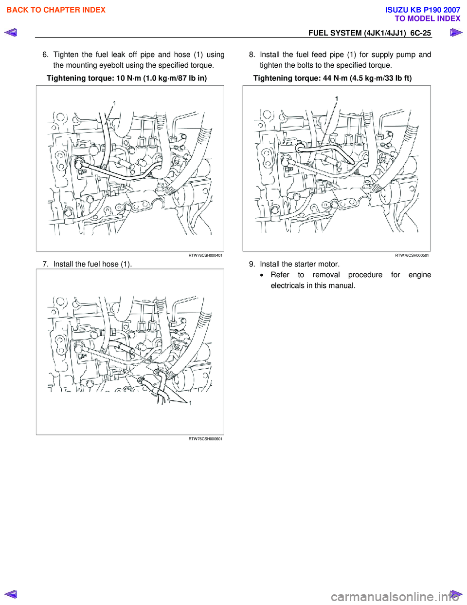
6. Tighten the fuel leak off pipe and hose (1) using
the mounting eyebolt using the specified torque.
Tightening torque: 10 N ⋅
⋅⋅
⋅
m (1.0 kg ⋅
⋅⋅
⋅
m/87 lb in)
RTW 76CSH000401
7. Install the fuel hose (1).
RTW 76CSH000601
8. Install the fuel feed pipe (1) for supply pump and
tighten the bolts to the specified torque.
Tightening torque: 44 N ⋅
⋅⋅
⋅
m (4.5 kg ⋅
⋅⋅
⋅
m/33 lb ft)
RTW 76CSH000501
9. Install the starter motor. • Refer to removal procedure for engine
electricals in this manual.
BACK TO CHAPTER INDEX
TO MODEL INDEX
ISUZU KB P190 2007
Page 1585 of 6020
6C-44 FUEL SYSTEM (4JK1/4JJ1)
Fuel Tube / Quick - Connector Fittings
Precautions
• Do not light a match or create a flame.
• Keep flames away from your work area to prevent
flammable materials from catching fire.
• Disconnect the battery ground cable to prevent
electrical shorts.
• Pre −treat the piping system or associated parts
from thermal damage or from spattering when
welding or similar heat −generating work.
Cautions During Work
Do not expose the assembly to battery electrolyte or do
not wipe the assembly with a cloth used to wipe off spilt
battery electrolyte.
Piping that has been splattered with battery electrolyte
or battery electrolyte soaked cloth that was wiped on the
piping cannot be used.
140R100032
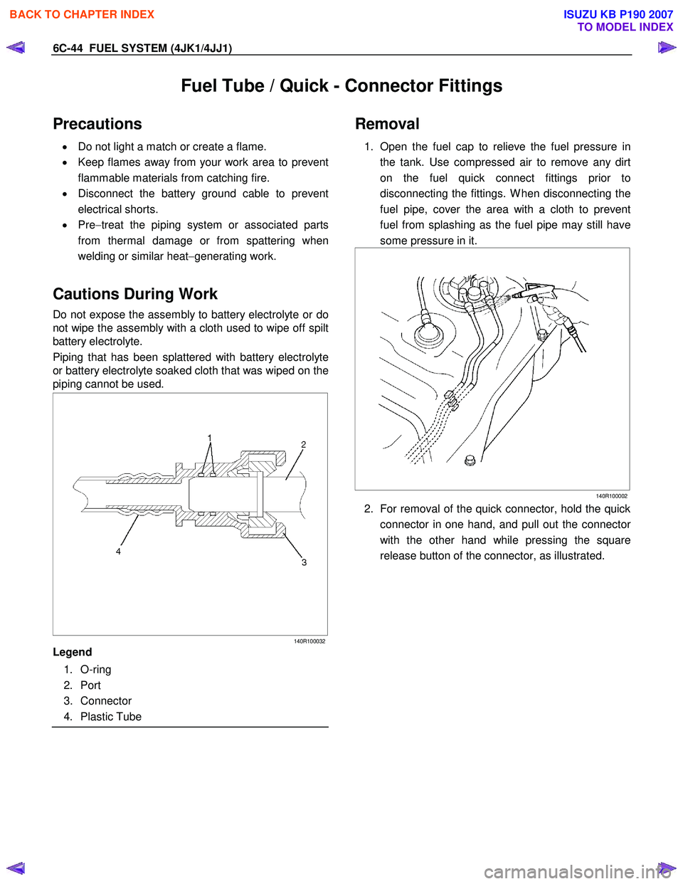
Legend
1. O-ring
2. Port
3. Connector
4. Plastic Tube
Removal
1. Open the fuel cap to relieve the fuel pressure in
the tank. Use compressed air to remove any dirt
on the fuel quick connect fittings prior to
disconnecting the fittings. W hen disconnecting the
fuel pipe, cover the area with a cloth to prevent
fuel from splashing as the fuel pipe may still have
some pressure in it.
140R100002
2. For removal of the quick connector, hold the quick
connector in one hand, and pull out the connecto
r
with the other hand while pressing the square
release button of the connector, as illustrated.
BACK TO CHAPTER INDEX
TO MODEL INDEX
ISUZU KB P190 2007
Page 1589 of 6020
ENGINE ELECTRICAL (4JK1/4JJ1) 6D-1
SECTION 6D
ENGINE ELECTRICAL
TABLE OF CONTENTS
Charging System ................................................ 6D-2
Servicing Cautions .......................................... 6D-2
Important Generator Components and
Function.......................................................... 6D-2
Troubleshooting .............................................. 6D-5
Diagnosis......................................................... 6D-7
Specifications .................................................. 6D-8
Unit Se rv ic ing (4 JJ 1) ....................................... .... ..6D -9
Disassembly .................................................... 6D-10
Inspection and Repair ..................................... 6D-11 Rotor Assembly ........................................... 6D-11
Stator Coil .................................................... 6D-12
Brushes ....................................................... 6D-12
Rectifier ....................................................... 6D-13
Regulator Assembly..................................... 6D-13
Measuring Procedure .................................. 6D-13
Reassembly..................................................... 6D-14
Final Assembly ................................................ 6D-14
Starter Motor ...................................................... 6D-15 Starting Circuit Diagram .................................. 6D-15
Removal and Installation ................................. 6D-15 Important Operations – Removal................. 6D-15
Important Operations – Installation.............. 6D-15
Disassembly .................................................... 6D-16 Disassembly Steps ...................................... 6D-16
Important Operations ................................... 6D-17
Inspection and Repair ..................................... 6D-20 Armature ...................................................... 6D-20
Yoke............................................................. 6D-21
Brush and Brush Holder .............................. 6D-22
Overrunning Clutch...................................... 6D-22
Bearing ........................................................ 6D-23
Reassembly..................................................... 6D-24 Reassembly Steps ....................................... 6D-24
Important Operations ................................... 6D-25
Inspection After Assembly ........................... 6D-26
Magnetic Switch .............................................. 6D-27
Torque Specifications...................................... 6D-28
Pre-Heating System ........................................... 6D-29 Inspection and Repair ..................................... 6D-29 Visual Check................................................ 6D-29
Glow Relay .................................................. 6D-29
Glow Plug .................................................... 6D-29
BACK TO CHAPTER INDEX
TO MODEL INDEX
ISUZU KB P190 2007
Page 1590 of 6020
6D-2 ENGINE ELECTRICAL (4JK1/4JJ1)
Charging System
Servicing Cautions
• Battery polarity is important. If the battery cables
are reversed, the generator diodes will be
destroyed.
• Do not remove the battery cables or the charging
circuit wiring when the engine is running.
• Confirm that the terminal wires are connected to
the proper terminals by checking the terminal
numbers (the number on the terminal wire and the
terminal must be the same).
• Disconnect the battery negative cable (-) before
inspecting the generator.
• Do not open or close the battery relay switch when
the engine is running.
• Disconnect the battery negative cable (-) when
using external equipment (Quick-Charge) to
charge the battery.
• W hen steam cleaning or washing the engine, do
not allow steam or water to come in direct contact
with the battery and other electrical system
components.
• Be sure to read the item on belt tension
adjustment before beginning the procedure.
Important Generator Components
and Function
• The generator used on 4JK1 engine cannot be
disassembled.
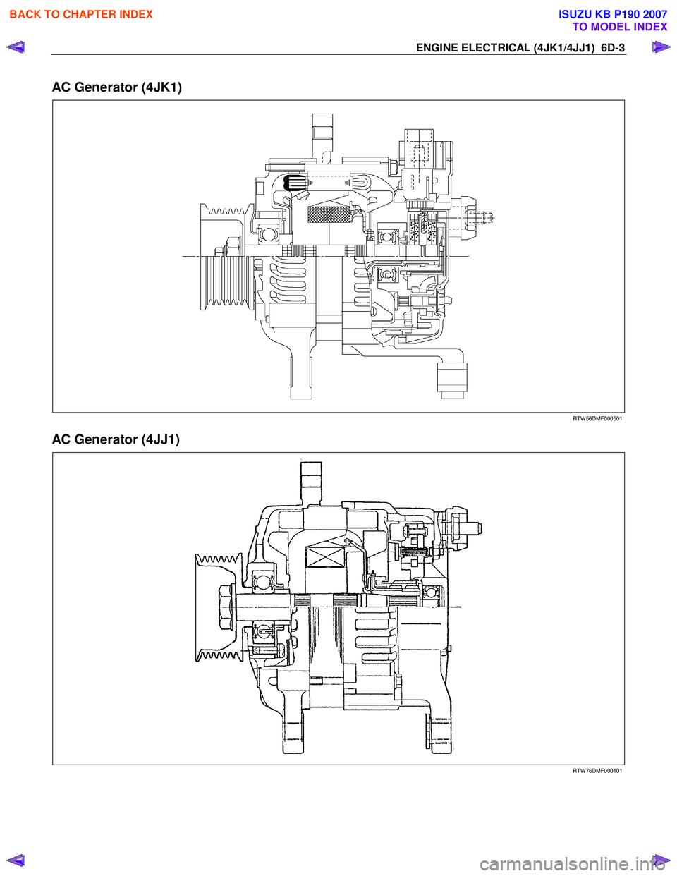
• The generator uses a built-in solid-state IC voltage
regulator. The regulator and other important
components together with their connections are
shown in the illustration.
• The voltage regulator is installed to the rear cove
r
assembly of the generator together with the brush
holder and the rectifier. The generator requires no
additional voltage regulation.
• 9 diodes are connected to the stator coil to convert
AC to DC. The DC voltage is delivered to the
generator output terminal.
BACK TO CHAPTER INDEX
TO MODEL INDEX
ISUZU KB P190 2007
Page 1591 of 6020
ENGINE ELECTRICAL (4JK1/4JJ1) 6D-3
AC Generator (4JK1)
RTW 56DMF000501
AC Generator (4JJ1)
RTW 76DMF000101
BACK TO CHAPTER INDEX
TO MODEL INDEX
ISUZU KB P190 2007