2007 ISUZU KB P190 lock
[x] Cancel search: lockPage 3780 of 6020

Automatic Transmission – 4L60E – General Information Page 7C1–20
8 Special Tools
The following pages list and illustrate the special service tools required. The tools are classified into the following
categories:
Mandatory:
W hen required to perform routine maintenance operations and adjustments, or are required to carry out
fault diagnosis procedures.
Desirable:
These tools should be considered for purchase since their use will greatly facilitate performing designated
tasks and permit achievement of standard times.
Unique: These tools are those that must be employed when overhauling major assemblies or performing relatively
large tasks.
Available: Are those tools that are of a general nature for which commercially available equivalents exist, or tools
which have had previous application.
Unless otherwise specified, all tools are available from:
SPX Australia PTY. LTD. Service Solutions 28 Clayton Road
Notting Hill, Victoria, 3168
Telephone: (03) 9544 6222
Facsimile: (03) 9544 5222
Tool Number Illustration Description Tool Classification
700-4208
Pass-Thru Connector Remover
Used to release the four locking tangs
on the Pass-Thru connector from the
transmission case.
Previously released Desirable
J6125-1B
Slide Hammer
Used for a number of bush removal
operations.
Previously released Unique
J8092
Driver Handle
Used for a number of bush installation
operations.
Previously released Unique
J8433 Puller
Used with J21427-01 to remove the
output speed sensor ring from the
main shaft.
Previously released Unique
J8763-02 Holding Fixture
Used in conjunction with holding
fixture base J3289-20 to hold
automatic transmission.
Previously released. Unique
BACK TO CHAPTER INDEX
TO MODEL INDEX
ISUZU KB P190 2007
Page 3796 of 6020
Automatic Transmission – 4L60E – Electrical Diagnosis Page 7C2–10
Limp Home Mode Description
If a major electrical system failure occurs which could affect vehicle safety or damage the transmission during normal
operation, the TCM enters a limp home mode. In the limp home mode, the transmission operates in the following
manner:
• The pressure control solenoid is off and the line pressure is at maximum to minimise clutch slippage.
• The TCC solenoid is off, therefore the torque converter clutch is disabled.
• The two shift solenoids are turned off. The transmission will operate in fourth gear if the vehicle has successfully
completed a 1-2 upshift in the current ignition cycle. If the vehicle has not completed a 1-2 upshift in the current
ignition cycle, the transmission will operate in third gear. If the transmission is operating in fourth gear, third gear
may be obtained if the engine is stopped briefly and re-started.
In limp home mode, the gear selector lever is ineffective at selecting forward gear ranges. In third or fourth gear, heat
builds up in the transmission quickly, particularly in stop and go traffic. Excessive heat build-up may cause transmission
failure if the vehicle is driven for extended distances in limp home mode.
1.3 Transmission Indicators and Messages
For information pertaining to the instrument cluster and the transmission information it displays, refer to the RA Rodeo
Owner Handbook.
1.4 Electronic Component Description
For all other electrical components not covered in this section, refer to General Motors Powertrain Group Electronically
Controlled Automatic Transmission Technician's Guide.
Transmission Control Module (TCM)
The Transmission Control Module (TCM) is located under the instrument panel, next to the brake pedal assembly and
connects directly to the transmission wiring harness. A single 49-way connector is used to make the connection between
the vehicle wiring harness and the TCM.
To access the connector for diagnosis:
1 Ensure the ignition switch is in the OFF position.
2 Disconnect the connector (1) from the transmission control module (TCM) (2) as follows, refer to Figure 7C2 – 2: a remove the securing pin (3),
b press the locking tab and swing the lever (4) to free the connector,
c remove the connector.
BACK TO CHAPTER INDEX
TO MODEL INDEX
ISUZU KB P190 2007
Page 3821 of 6020
Automatic Transmission – 4L60E – Electrical Diagnosis Page 7C2–35
Step Action Yes No
3 1 Inspect the engine cooling system and transmission cooling
system for the following conditions:
• Air flow restrictions
• Air flow blockage
• Debris
2 Inspect the transmission cooling system for damaged cooler lines.
3 Check the flow rate of the transmission fluid, refer to 7C4 Automatic Transmission – 4L60E – On-vehicle Servicing.
Did you find and correct the condition? Go to Step 6 Go to Step 4
4 Test for correct line pressure, refer to 7C3 Automatic Transmission –
4L60E – Hydraulic and Mechanical Diagnosis.
Did you find and correct the condition? Go to Step 6 Go to Step 5
5 Diagnose the torque converter stator, refer to 7C3 Automatic
Transmission – 4L60E – Hydraulic and Mechanical Diagnosis.
Did you find and correct the condition? Go to Step 6 Check for an
intermittent fault in the circuit, refer to
8A Electrical-Body
and Chassis
6 Perform the following procedure to verify the repair:
1 On Tech 2 select: Diagnostic Trouble Codes / Clear Engine & Transmission
DTCs.
2 Follow the instructions on Tech 2 and clear any DTCs.
3 Start and idle the engine until it reaches normal operating temperature.
4 On Tech 2 select: Data Display / Transmission Data.
5 Drive the vehicle for 10 minutes.
6 On Tech 2, monitor the Transmission Fluid Temp. and ensure
it has stabilised and is less than 129°C.
7 On Tech 2 select:
Diagnostic Trouble Codes / Read DTC Information.
Has DTC P0218 set? Go to Step 2 Go to Step 7
7 On Tech 2 select:
Diagnostic Trouble Codes / Read DTC Information.
Does Tech 2 display any DTCs you have not diagnosed? Refer to
4.8 Diagnostic Trouble Code List System OK
When all diagnosis and repairs are completed, check the
system for correct operation.
4.10 DTC P0562 – System Voltage Low
DTC Description
This diagnostic procedure supports DTC P0562 System Voltage Low.
Circuit Description
The transmission control module (TCM) continuously monitors the system voltage on the battery and ignition circuits.
Lower than normal voltage may be inadequate to operate the transmission control solenoids properly. Improper solenoid
operation may cause erratic transmission operation and tie-up conditions, which may result in internal damage.
BACK TO CHAPTER INDEX
TO MODEL INDEX
ISUZU KB P190 2007
Page 3832 of 6020
Automatic Transmission – 4L60E – Electrical Diagnosis Page 7C2–46
Step Action Yes No
3 Inspect the transmission and related components for the following:
• transmission fluid level,
• transmission fluid cooling system restrictions / blockages,
• debris in the transmission fluid,
• incorrect line pressure,
• torque converter stator operation, and
• transmission overload.
W as a fault found and rectified? Go to Step 10 Check for an
intermittent fault in
the circuit, refer to
8A Electrical-Body and Chassis
4 1 Switch off the ignition.
2 Disconnect connector E-95 from the transmission.
3 Using a multimeter set to measure voltage, probe between harness connector E-95 pin 16 and a known ground.
Does the multimeter display 4.8 – 5.2 V? Go to Step 6 Go to Step 5
5 Test the TFT sensor signal circuit (between connectors E-95 pin 16
and C-96 pin 35) for a high resistance, open circuit, short to ground or
short to voltage fault condition.
Did you find and correct the condition? Go to Step 10 Go to Step 9
6 1 Switch off the ignition.
2 Remove the TCM fuses C-8 and EB-4, refer to 8A Electrical- Body and Chassis.
3 Using a multimeter set to measure resistance, probe between connector E95 pin 15 and a known ground.
Does the multimeter display less than 5 Ω? Go to Step 8 Go to Step 7
7 Using a multimeter, test between E-95 pin 15 and C-96 pin 30 for high
resistance, open circuit, short to ground or short to voltage fault
condition.
W as any fault found and rectified? Go to Step 10 —
8 Replace the TFT sensor, refer to 7C4 Automatic Transmission –
4L60E – On-vehicle Servicing.
NOTE
Check for damaged wiring (short to ground, short to
voltage, high resistance or open circuit) or poor
connections inside the transmission assembly before
replacing the TFT sensor.
Was the repair complete? Go to Step 10 —
9 Replace the TCM, refer to 7C4 Automatic Transmission – 4L60E –
On-vehicle Servicing
Was the repair completed? Go to Step 10
—
BACK TO CHAPTER INDEX
TO MODEL INDEX
ISUZU KB P190 2007
Page 3844 of 6020
Automatic Transmission – 4L60E – Electrical Diagnosis Page 7C2–58
Conditions for Running the DTC
• No DTCs P0722, P0723, P0742, P2763 or P2764.
• The IMS range is D2, D3 or D4.
• Ignition voltage is 8 – 18 V.
• The transmission fluid temperature is greater than 20°C.
• The engine torque is 108 – 881 Nm.
• The throttle position is greater than 10 percent.
• The gear ratio is within the following ranges:
• 1.41:1 – 1.56:1 — 2nd gear,
• 0.95:1 – 1.05:1 — 3rd gear.
• The TCC is commanded on 0.1 seconds.
• The TCC duty cycle is greater than 60 percent for more than 3 seconds.
Conditions for Setting the DTC
The TCM commands the TCC on, and the TCC slip is greater than 250 r.p.m. for 3 seconds.
Action Taken When the DTC Sets
•
The TCM requests the ECM to illuminate the MIL during the second consecutive drive trip in which the conditions
for setting the DTC are met.
• The TCM inhibits TCC.
• The TCM inhibits 4th gear if the transmission is in Hot Mode.
• The TCM commands elevated line pressure.
• The TCM freezes transmission adaptive functions.
• At the time of the first failure, the TCM records the operating conditions when the conditions for setting the DTC are
met. The TCM stores this information as a Failure Record.
• At the time of the second failure, the ECM records the operating conditions when the conditions for setting the DTC
are met. The ECM stores this information as a Freeze Frame.
• The TCM stores DTC P0741 in TCM history.
Conditions for Clearing the DTC
• The ECM turns off the MIL after the sixth consecutive drive trip in which the TCM does not send a MIL illumination
request.
• Tech 2 can clear the DTC.
• The TCM clears the DTC from TCM history if the vehicle completes 40 warm-up cycles without a non-emission
related diagnostic fault occurring.
• The TCM cancels the default actions when the ignition is off long enough to power down the TCM.
Diagnostic Aids
• Inspect the transmission fluid lines to the radiator. The lines may be pinched, blocked or twisted.
• Contamination may cause the TCC apply valve to stick in the valve body.
• Internal damage to the torque converter may prevent TCC application.
Test Description
The following numbers refer to the step numbers in the diagnostic table:
BACK TO CHAPTER INDEX
TO MODEL INDEX
ISUZU KB P190 2007
Page 3848 of 6020
Automatic Transmission – 4L60E – Electrical Diagnosis Page 7C2–62
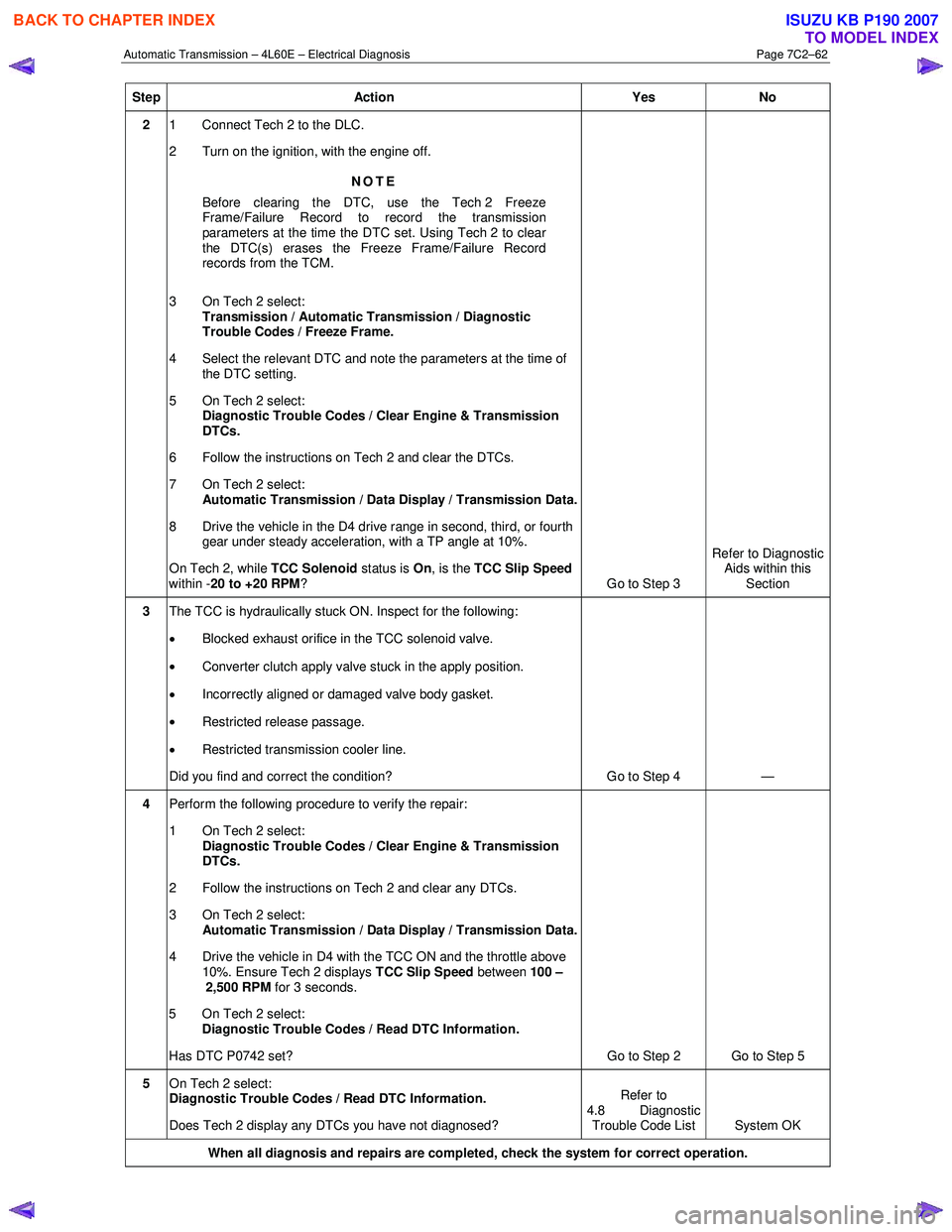
Step Action Yes No
2 1 Connect Tech 2 to the DLC.
2 Turn on the ignition, with the engine off.
NOTE
Before clearing the DTC, use the Tech 2 Freeze
Frame/Failure Record to record the transmission
parameters at the time the DTC set. Using Tech 2 to clear
the DTC(s) erases the Freeze Frame/Failure Record
records from the TCM.
3 On Tech 2 select: Transmission / Automatic Transmission / Diagnostic
Trouble Codes / Freeze Frame.
4 Select the relevant DTC and note the parameters at the time of the DTC setting.
5 On Tech 2 select:
Diagnostic Trouble Codes / Clear Engine & Transmission
DTCs.
6 Follow the instructions on Tech 2 and clear the DTCs.
7 On Tech 2 select: Automatic Transmission / Data Display / Transmission Data.
8 Drive the vehicle in the D4 drive range in second, third, or fourth gear under steady acceleration, with a TP angle at 10%.
On Tech 2, while TCC Solenoid status is On, is the TCC Slip Speed
within - 20 to +20 RPM ? Go to Step 3 Refer to Diagnostic
Aids within this Section
3 The TCC is hydraulically stuck ON. Inspect for the following:
• Blocked exhaust orifice in the TCC solenoid valve.
• Converter clutch apply valve stuck in the apply position.
• Incorrectly aligned or damaged valve body gasket.
• Restricted release passage.
• Restricted transmission cooler line.
Did you find and correct the condition? Go to Step 4 —
4 Perform the following procedure to verify the repair:
1 On Tech 2 select: Diagnostic Trouble Codes / Clear Engine & Transmission
DTCs.
2 Follow the instructions on Tech 2 and clear any DTCs.
3 On Tech 2 select: Automatic Transmission / Data Display / Transmission Data.
4 Drive the vehicle in D4 with the TCC ON and the throttle above 10%. Ensure Tech 2 displays TCC Slip Speed between 100 –
2,500 RPM for 3 seconds.
5 On Tech 2 select:
Diagnostic Trouble Codes / Read DTC Information.
Has DTC P0742 set? Go to Step 2 Go to Step 5
5 On Tech 2 select:
Diagnostic Trouble Codes / Read DTC Information.
Does Tech 2 display any DTCs you have not diagnosed? Refer to
4.8 Diagnostic Trouble Code List System OK
When all diagnosis and repairs are completed, check the system for correct operation.
BACK TO CHAPTER INDEX
TO MODEL INDEX
ISUZU KB P190 2007
Page 3850 of 6020
Automatic Transmission – 4L60E – Electrical Diagnosis Page 7C2–64
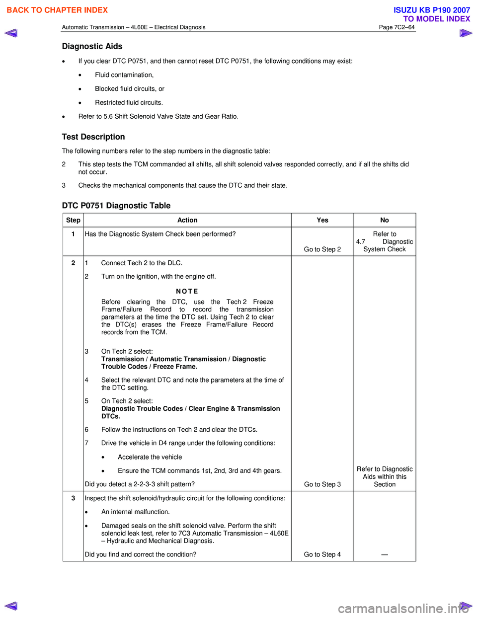
Diagnostic Aids
• If you clear DTC P0751, and then cannot reset DTC P0751, the following conditions may exist:
• Fluid contamination,
• Blocked fluid circuits, or
• Restricted fluid circuits.
• Refer to 5.6 Shift Solenoid Valve State and Gear Ratio.
Test Description
The following numbers refer to the step numbers in the diagnostic table:
2 This step tests the TCM commanded all shifts, all shift solenoid valves responded correctly, and if all the shifts did not occur.
3 Checks the mechanical components that cause the DTC and their state.
DTC P0751 Diagnostic Table
Step Action Yes No
1 Has the Diagnostic System Check been performed?
Go to Step 2 Refer to
4.7 Diagnostic System Check
2 1 Connect Tech 2 to the DLC.
2 Turn on the ignition, with the engine off.
NOTE
Before clearing the DTC, use the Tech 2 Freeze
Frame/Failure Record to record the transmission
parameters at the time the DTC set. Using Tech 2 to clear
the DTC(s) erases the Freeze Frame/Failure Record
records from the TCM.
3 On Tech 2 select: Transmission / Automatic Transmission / Diagnostic
Trouble Codes / Freeze Frame.
4 Select the relevant DTC and note the parameters at the time of the DTC setting.
5 On Tech 2 select:
Diagnostic Trouble Codes / Clear Engine & Transmission
DTCs.
6 Follow the instructions on Tech 2 and clear the DTCs.
7 Drive the vehicle in D4 range under the following conditions:
• Accelerate the vehicle
• Ensure the TCM commands 1st, 2nd, 3rd and 4th gears.
Did you detect a 2-2-3-3 shift pattern? Go to Step 3 Refer to Diagnostic
Aids within this Section
3 Inspect the shift solenoid/hydraulic circuit for the following conditions:
• An internal malfunction.
• Damaged seals on the shift solenoid valve. Perform the shift
solenoid leak test, refer to 7C3 Automatic Transmission – 4L60E
– Hydraulic and Mechanical Diagnosis.
Did you find and correct the condition? Go to Step 4 —
BACK TO CHAPTER INDEX
TO MODEL INDEX
ISUZU KB P190 2007
Page 3852 of 6020
Automatic Transmission – 4L60E – Electrical Diagnosis Page 7C2–66
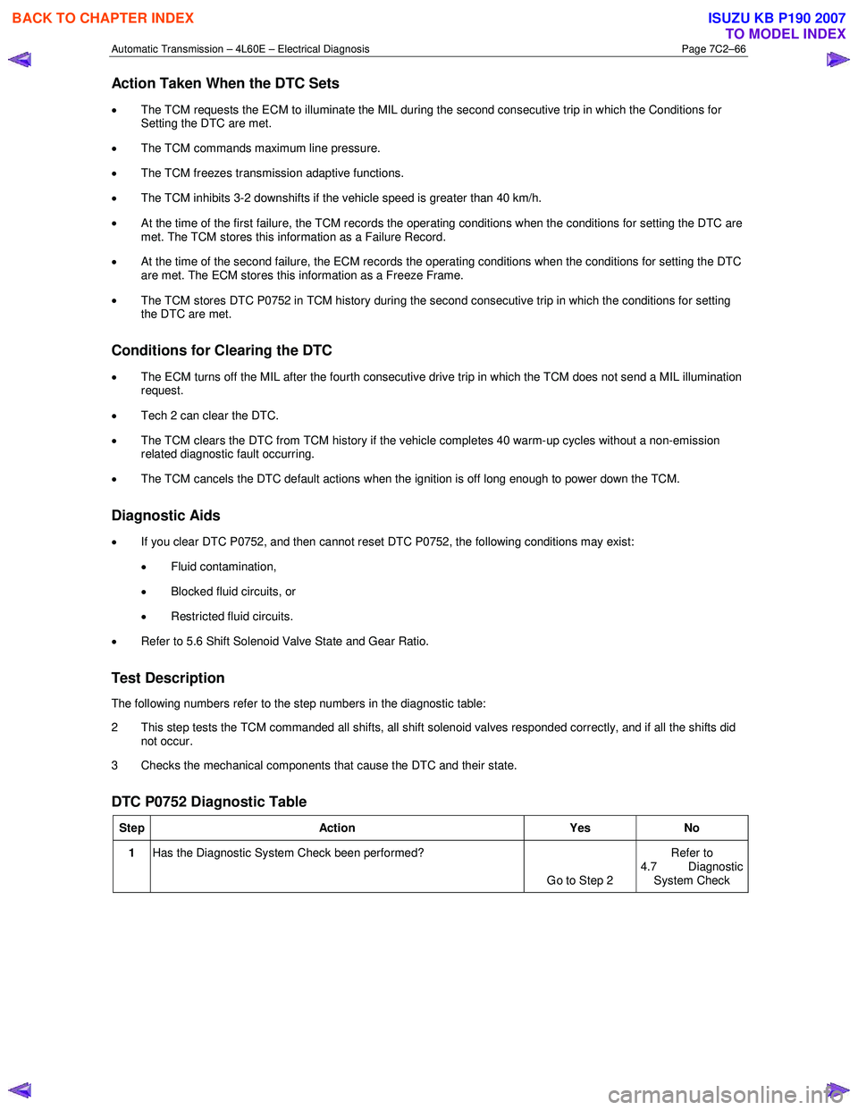
Action Taken When the DTC Sets
• The TCM requests the ECM to illuminate the MIL during the second consecutive trip in which the Conditions for
Setting the DTC are met.
• The TCM commands maximum line pressure.
• The TCM freezes transmission adaptive functions.
• The TCM inhibits 3-2 downshifts if the vehicle speed is greater than 40 km/h.
• At the time of the first failure, the TCM records the operating conditions when the conditions for setting the DTC are
met. The TCM stores this information as a Failure Record.
• At the time of the second failure, the ECM records the operating conditions when the conditions for setting the DTC
are met. The ECM stores this information as a Freeze Frame.
• The TCM stores DTC P0752 in TCM history during the second consecutive trip in which the conditions for setting
the DTC are met.
Conditions for Clearing the DTC
• The ECM turns off the MIL after the fourth consecutive drive trip in which the TCM does not send a MIL illumination
request.
• Tech 2 can clear the DTC.
• The TCM clears the DTC from TCM history if the vehicle completes 40 warm-up cycles without a non-emission
related diagnostic fault occurring.
• The TCM cancels the DTC default actions when the ignition is off long enough to power down the TCM.
Diagnostic Aids
• If you clear DTC P0752, and then cannot reset DTC P0752, the following conditions may exist:
• Fluid contamination,
• Blocked fluid circuits, or
• Restricted fluid circuits.
• Refer to 5.6 Shift Solenoid Valve State and Gear Ratio.
Test Description
The following numbers refer to the step numbers in the diagnostic table:
2 This step tests the TCM commanded all shifts, all shift solenoid valves responded correctly, and if all the shifts did not occur.
3 Checks the mechanical components that cause the DTC and their state.
DTC P0752 Diagnostic Table
Step Action Yes No
1 Has the Diagnostic System Check been performed?
Go to Step 2 Refer to
4.7 Diagnostic
System Check
BACK TO CHAPTER INDEX
TO MODEL INDEX
ISUZU KB P190 2007