2007 ISUZU KB P190 lock
[x] Cancel search: lockPage 3629 of 6020
Starting System – V6 Page 6D1-2–21
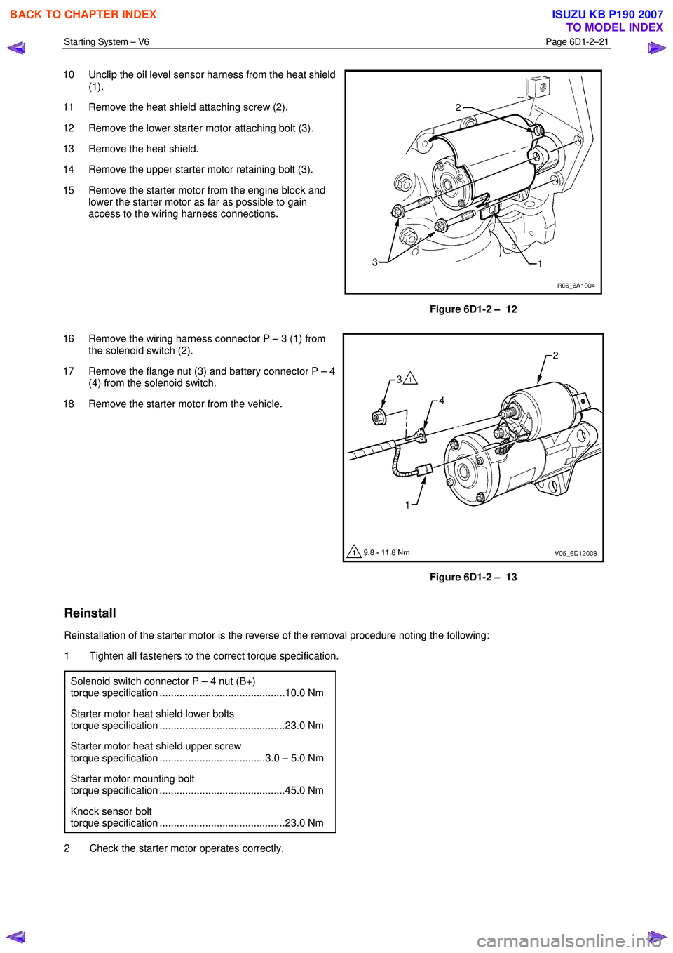
10 Unclip the oil level sensor harness from the heat shield
(1).
11 Remove the heat shield attaching screw (2).
12 Remove the lower starter motor attaching bolt (3).
13 Remove the heat shield.
14 Remove the upper starter motor retaining bolt (3).
15 Remove the starter motor from the engine block and lower the starter motor as far as possible to gain
access to the wiring harness connections.
Figure 6D1-2 – 12
16 Remove the wiring harness connector P – 3 (1) from the solenoid switch (2).
17 Remove the flange nut (3) and battery connector P – 4 (4) from the solenoid switch.
18 Remove the starter motor from the vehicle.
Figure 6D1-2 – 13
Reinstall
Reinstallation of the starter motor is the reverse of the removal procedure noting the following:
1 Tighten all fasteners to the correct torque specification.
Solenoid switch connector P – 4 nut (B+)
torque specification ............................................10.0 Nm
Starter motor heat shield lower bolts
torque specification ............................................23.0 Nm
Starter motor heat shield upper screw
torque specification .....................................3.0 – 5.0 Nm
Starter motor mounting bolt
torque specification ............................................45.0 Nm
Knock sensor bolt
torque specification ............................................23.0 Nm
2 Check the starter motor operates correctly.
BACK TO CHAPTER INDEX
TO MODEL INDEX
ISUZU KB P190 2007
Page 3638 of 6020
Starting System – V6 Page 6D1-2–30
5 Specifications
Type............................................... Six Pole Permanent Magnet, Four Brush, Planetary Drive
Rotation (Drive-End View) ....................................................................................... Clockwise
Number of Pinion Teeth ........................................................................................................ 1 0
No load:
Minimum RPM .................................................................................................................. 23 70
Maximum Current Draw ............................................................................ 65 A at 12.0 ± 0.1 V
M Terminal Voltage..................................................................................................... 12 ± 1 V
Locked:
Maximum Current (Including Solenoid Switch) ............................................................... 780 A
M Terminal Voltage............................................................................................................. 4 V
Minimum Torque ............................................................................................................ 20 Nm
Solenoid detached:
Pull-in Winding Resistance @ 20°C ................................................................... 0.33 – 0.37 Ω
Hold-in Winding Resistance @ 20°C .................................................................. 0.75 – 0.87 Ω
Pull-in Voltage @ 20°C .......................................................................................... 8 V @ 20 °C
Hold-in Voltage @ 20°C.......................................................................................... 1.7 – 3.0 V
BACK TO CHAPTER INDEX
TO MODEL INDEX
ISUZU KB P190 2007
Page 3652 of 6020
Battery Page 6D1-3–12
9 Lock the doors and activate the theft deterrent system to arm the vehicle.
10 If the multimeter contains fuses, check they are serviceable.
Test Procedure
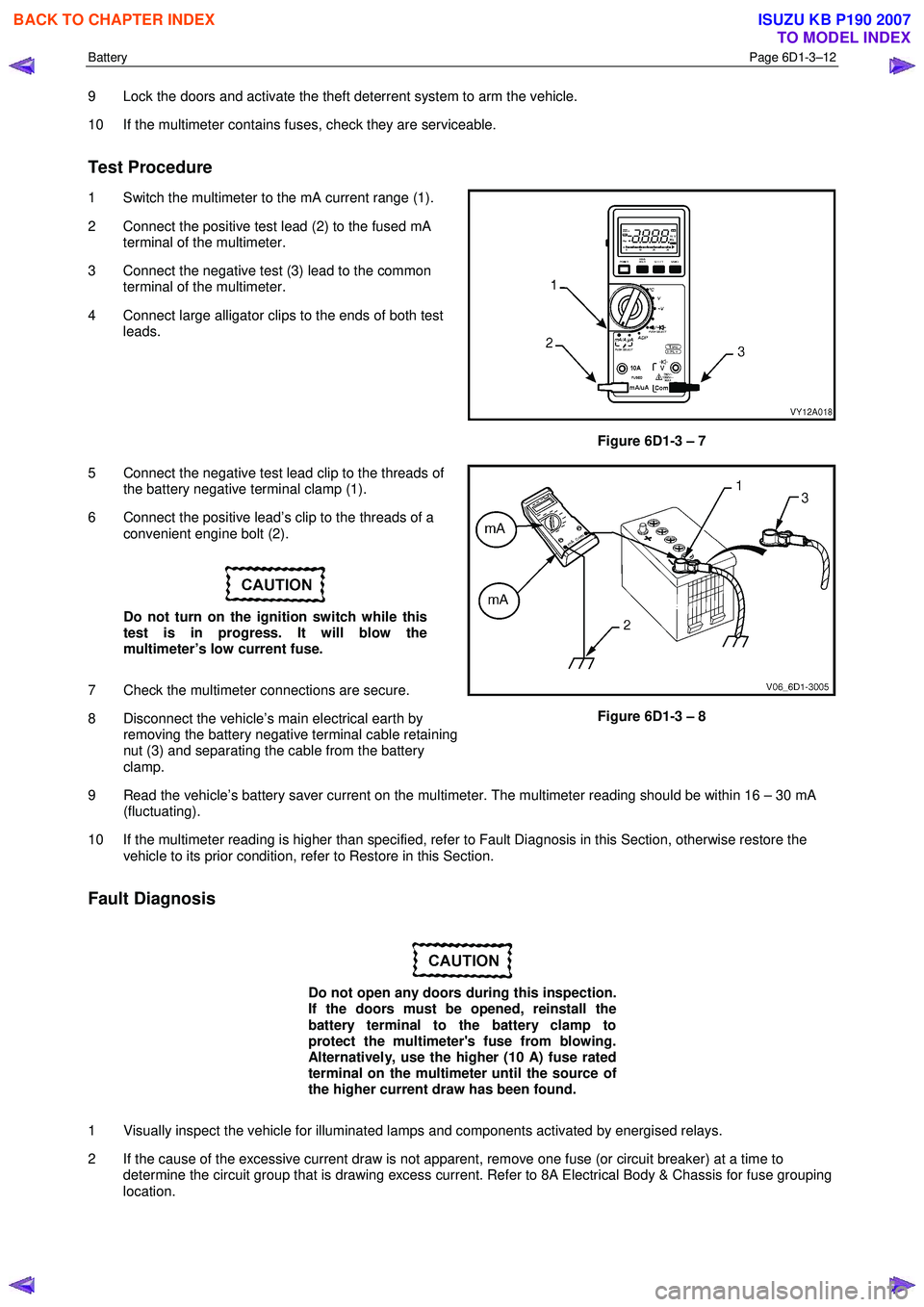
1 Switch the multimeter to the mA current range (1).
2 Connect the positive test lead (2) to the fused mA terminal of the multimeter.
3 Connect the negative test (3) lead to the common terminal of the multimeter.
4 Connect large alligator clips to the ends of both test leads.
Figure 6D1-3 – 7
5 Connect the negative test lead clip to the threads of the battery negative terminal clamp (1).
6 Connect the positive lead’s clip to the threads of a convenient engine bolt (2).
Do not turn on the ignition switch while this
test is in progress. It will blow the
multimeter’s low current fuse.
7 Check the multimeter connections are secure.
8 Disconnect the vehicle’s main electrical earth by removing the battery negative terminal cable retaining
nut (3) and separating the cable from the battery
clamp.
Figure 6D1-3 – 8
9 Read the vehicle’s battery saver current on the multimeter. The multimeter reading should be within 16 – 30 mA (fluctuating).
10 If the multimeter reading is higher than specified, refer to Fault Diagnosis in this Section, otherwise restore the vehicle to its prior condition, refer to Restore in this Section.
Fault Diagnosis
Do not open any doors during this inspection.
If the doors must be opened, reinstall the
battery terminal to the battery clamp to
protect the multimeter's fuse from blowing.
Alternatively, use the higher (10 A) fuse rated
terminal on the multimeter until the source of
the higher current draw has been found.
1 Visually inspect the vehicle for illuminated lamps and components activated by energised relays.
2 If the cause of the excessive current draw is not apparent, remove one fuse (or circuit breaker) at a time to determine the circuit group that is drawing excess current. Refer to 8A Electrical Body & Chassis for fuse grouping
location.
BACK TO CHAPTER INDEX
TO MODEL INDEX
ISUZU KB P190 2007
Page 3686 of 6020
Powertrain Interface Module – V6 Page 6E1–25
• Thorough inspection of the wiring circuits and connectors listed in the diagnostic procedures must be performed,
otherwise misdiagnosis may occur.
• Inspect the electrical circuitry or connector terminals that are suspected to be causing the complaint for the
following conditions:
• backed-out connector terminals,
• improper wiring connector mating,
• broken wiring connector locks,
• damaged connector terminals, and
• physical damage to the wiring harness.
• Before replacing a component, inspect its connector terminal for corrosion or deformation that may cause the fault
condition.
Preliminary Checks
The PIM preliminary check examines easily accessible components which may cause problems with the PIM. This visual
and physical inspection procedure may quickly identify the fault condition and eliminate the need for additional diagnosis.
• Refer to Service Techlines for relevant information regarding the fault condition.
• Ensure the battery is fully charged.
• Check the battery connections for corrosion or a loose terminal.
• Perform a visual and physical inspection of the following:
• PIM component wiring harness and terminals for proper connections, pinches or cuts, and
• PIM wiring harness routing which may be positioned very close to a high voltage or high current devices such
as aftermarket audio systems.
NOTE
High voltage or high current devices may induce
electrical noise on a circuit, which can interfere
with normal circuit operation.
• The PIM is sensitive to Electro Magnetic Interference (EMI). Check for incorrect aftermarket theft deterrent
devices, lights or mobile phone installations if an intermittent malfunction is suspected.
7.2 Diagnostic System Check
Step Action Yes No
1
Have you met the basic diagnostic requirements listed in the PIM
Diagnostic Starting Point?
Go to Step 2 Refer to
7.1 Diagnostic
Requirements,
Precautions and
Preliminary Checks
2 Have you read the Diagnostic Precautions?
Go to Step 3 Refer to
7.1 Diagnostic Requirements,
Precautions and
Preliminary Checks
3 Have you performed the Preliminary Checks?
Go to Step 4 Refer to
7.1 Diagnostic Requirements,
Precautions and
Preliminary Checks
BACK TO CHAPTER INDEX
TO MODEL INDEX
ISUZU KB P190 2007
Page 3718 of 6020
Powertrain Interface Module – V6 Page 6E1–57
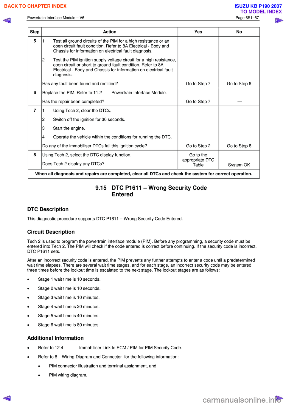
Step Action Yes No
5
1 Test all ground circuits of the PIM for a high resistance or an
open circuit fault condition. Refer to 8A Electrical - Body and
Chassis for information on electrical fault diagnosis.
2 Test the PIM ignition supply voltage circuit for a high resistance, open circuit or short to ground fault condition. Refer to 8A
Electrical - Body and Chassis for information on electrical fault
diagnosis.
Has any fault been found and rectified? Go to Step 7 Go to Step 6
6 Replace the PIM. Refer to 11.2 Powertrain Interface Module.
Has the repair been completed? Go to Step 7 —
7 1 Using Tech 2, clear the DTCs.
2 Switch off the ignition for 30 seconds.
3 Start the engine.
4 Operate the vehicle within the conditions for running the DTC.
Do any of the immobiliser DTCs fail this ignition cycle? Go to Step 2 Go to Step 8
8
Using Tech 2, select the DTC display function.
Does Tech 2 display any DTCs? Go to the
appropriate DTC Table System OK
When all diagnosis and repairs are completed, clear all DTCs and check the system for correct operation.
9.15 DTC P1611 – Wrong Security Code
Entered
DTC Description
This diagnostic procedure supports DTC P1611 – W rong Security Code Entered.
Circuit Description
Tech 2 is used to program the powertrain interface module (PIM). Before any programming, a security code must be
entered into Tech 2. The PIM will check if the code entered is correct before continuing. If the security code is incorrect,
DTC P1611 sets.
After an incorrect security code is entered, the PIM prevents any further attempts to enter a code until a predetermined
wait time elapses. There are several wait time stages, and for each stage, an incorrect security code may be entered
three times before the lockout time is escalated to the next stage. The lockout stages are as follows:
• Stage 1 wait time is 10 seconds.
• Stage 2 wait time is 10 seconds.
• Stage 3 wait time is 10 minutes.
• Stage 4 wait time is 20 minutes.
• Stage 5 wait time is 40 minutes.
• Stage 6 wait time is 80 minutes.
Additional Information
• Refer to 12.4 Immobiliser Link to ECM / PIM for PIM Security Code.
• Refer to 6 W iring Diagram and Connector for the following information:
• PIM connector illustration and terminal assignment, and
• PIM wiring diagram.
BACK TO CHAPTER INDEX
TO MODEL INDEX
ISUZU KB P190 2007
Page 3719 of 6020
Powertrain Interface Module – V6 Page 6E1–58
• For intermittent fault conditions, refer to Intermittent Fault Conditions.
• Since fault conditions in a wiring connector may trigger DTCs, always test the connectors related to this diagnostic
procedure for shorted terminals or poor wiring connection before replacing any component. Refer to 8A Electrical -
Body and Chassis for information on electrical fault diagnosis.
Conditions for Running the DTC
Conditions for running the DTC are:
• The ignition is switched on.
• The ignition voltage is 10.0 – 16.0 V.
Conditions for Setting the DTC
An incorrect security code is entered into Tech 2 when attempting to program the PIM.
Action Taken When the DTC Sets
W hen the DTC sets, the following action is taken:
• The vehicle will not start whilst the PIM is in a lock-out state.
NOTE
When the DTC sets, there is no warning lamp
displayed on the instrument cluster.
Conditions for Clearing the DTC
Refer to 4.1 Diagnostic General Descriptions for information on the conditions for clearing DTCs.
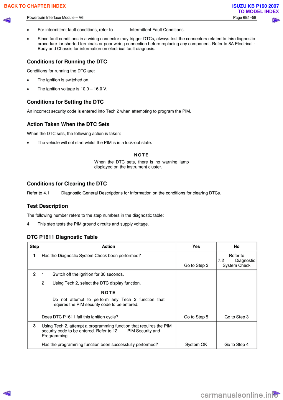
Test Description
The following number refers to the step numbers in the diagnostic table:
4 This step tests the PIM ground circuits and supply voltage.
DTC P1611 Diagnostic Table
Step Action Yes No
1
Has the Diagnostic System Check been performed?
Go to Step 2 Refer to
7.2 Diagnostic System Check
2 1 Switch off the ignition for 30 seconds.
2 Using Tech 2, select the DTC display function.
NOTE
Do not attempt to perform any Tech 2 function that
requires the PIM security code to be entered.
Does DTC P1611 fail this ignition cycle? Go to Step 5 Go to Step 3
3 Using Tech 2, attempt a programming function that requires the PIM
security code to be entered. Refer to 12 PIM Security and
Programming.
Has the programming function been successfully performed? System OK Go to Step 4
BACK TO CHAPTER INDEX
TO MODEL INDEX
ISUZU KB P190 2007
Page 3751 of 6020
Exhaust System – V6 Page 6F – 3
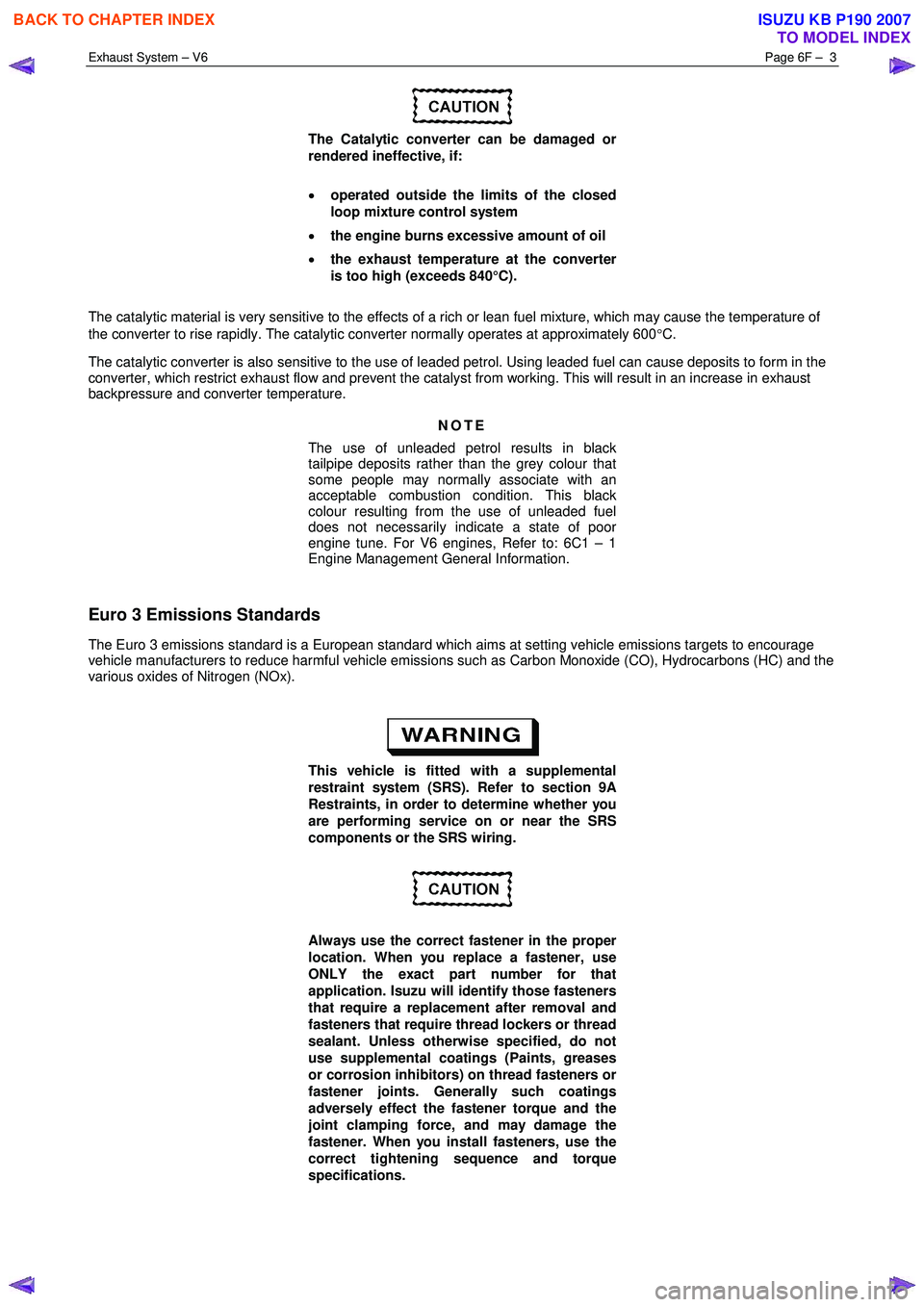
The Catalytic converter can be damaged or
rendered ineffective, if:
• operated outside the limits of the closed
loop mixture control system
• the engine burns excessive amount of oil
• the exhaust temperature at the converter
is too high (exceeds 840°C).
The catalytic material is very sensitive to the effects of a rich or lean fuel mixture, which may cause the temperature of
the converter to rise rapidly. The catalytic converter normally operates at approximately 600 °C.
The catalytic converter is also sensitive to the use of leaded petrol. Using leaded fuel can cause deposits to form in the
converter, which restrict exhaust flow and prevent the catalyst from working. This will result in an increase in exhaust
backpressure and converter temperature.
NOTE
The use of unleaded petrol results in black
tailpipe deposits rather than the grey colour that
some people may normally associate with an
acceptable combustion condition. This black
colour resulting from the use of unleaded fuel
does not necessarily indicate a state of poor
engine tune. For V6 engines, Refer to: 6C1 – 1
Engine Management General Information.
Euro 3 Emissions Standards
The Euro 3 emissions standard is a European standard which aims at setting vehicle emissions targets to encourage
vehicle manufacturers to reduce harmful vehicle emissions such as Carbon Monoxide (CO), Hydrocarbons (HC) and the
various oxides of Nitrogen (NOx).
This vehicle is fitted with a supplemental
restraint system (SRS). Refer to section 9A
Restraints, in order to determine whether you
are performing service on or near the SRS
components or the SRS wiring.
Always use the correct fastener in the proper
location. When you replace a fastener, use
ONLY the exact part number for that
application. Isuzu will identify those fasteners
that require a replacement after removal and
fasteners that require thread lockers or thread
sealant. Unless otherwise specified, do not
use supplemental coatings (Paints, greases
or corrosion inhibitors) on thread fasteners or
fastener joints. Generally such coatings
adversely effect the fastener torque and the
joint clamping force, and may damage the
fastener. When you install fasteners, use the
correct tightening sequence and torque
specifications.
BACK TO CHAPTER INDEX
TO MODEL INDEX
ISUZU KB P190 2007
Page 3752 of 6020
Exhaust System – V6 Page 6F – 4
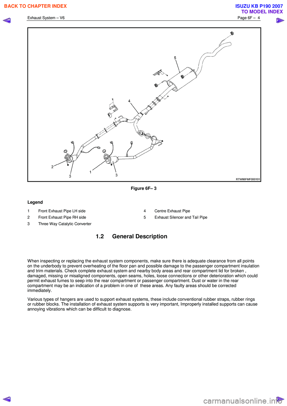
Figure 6F– 3
Legend
1 Front Exhaust Pipe LH side
2 Front Exhaust Pipe RH side
3 Three Way Catalytic Converter 4 Centre Exhaust Pipe
5 Exhaust Silencer and Tail Pipe
1.2 General Description
W hen inspecting or replacing the exhaust system components, make sure there is adequate clearance from all points
on the underbody to prevent overheating of the floor pan and possible damage to the passenger compartment insulation
and trim materials. Check complete exhaust system and nearby body areas and rear compartment lid for broken ,
damaged, missing or misaligned components, open seams, holes, loose connections or other deterioration which could
permit exhaust fumes to seep into the rear compartment or passenger compartment. Dust or water in the rear
compartment may be an indication of a problem in one of these areas. Any faulty areas should be corrected
immediately.
Various types of hangers are used to support exhaust systems, these include conventional rubber straps, rubber rings
or rubber blocks. The installation of exhaust system supports is very important, Improperly installed supports can cause
annoying vibrations which can be difficult to diagnose.
BACK TO CHAPTER INDEX
TO MODEL INDEX
ISUZU KB P190 2007