2007 ISUZU KB P190 lock
[x] Cancel search: lockPage 3348 of 6020
Engine Management – V6 – Diagnostics Page 6C1-2–70
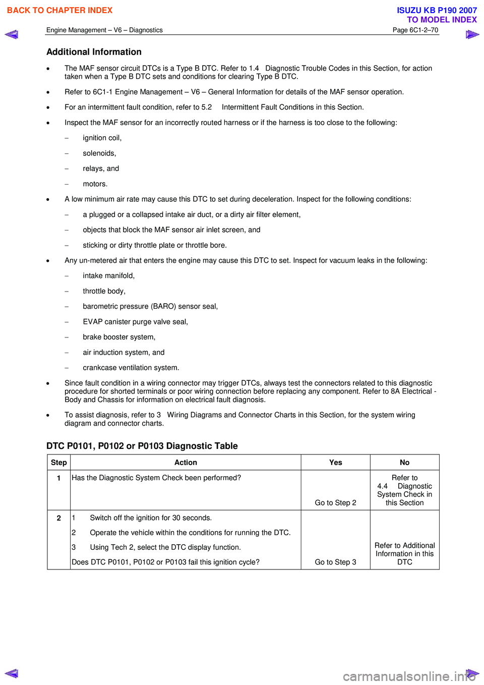
Additional Information
• The MAF sensor circuit DTCs is a Type B DTC. Refer to 1.4 Diagnostic Trouble Codes in this Section, for action
taken when a Type B DTC sets and conditions for clearing Type B DTC.
• Refer to 6C1-1 Engine Management – V6 – General Information for details of the MAF sensor operation.
• For an intermittent fault condition, refer to 5.2 Intermittent Fault Conditions in this Section.
• Inspect the MAF sensor for an incorrectly routed harness or if the harness is too close to the following:
− ignition coil,
− solenoids,
− relays, and
− motors.
• A low minimum air rate may cause this DTC to set during deceleration. Inspect for the following conditions:
− a plugged or a collapsed intake air duct, or a dirty air filter element,
− objects that block the MAF sensor air inlet screen, and
− sticking or dirty throttle plate or throttle bore.
• Any un-metered air that enters the engine may cause this DTC to set. Inspect for vacuum leaks in the following:
− intake manifold,
− throttle body,
− barometric pressure (BARO) sensor seal,
− EVAP canister purge valve seal,
− brake booster system,
− air induction system, and
− crankcase ventilation system.
• Since fault condition in a wiring connector may trigger DTCs, always test the connectors related to this diagnostic
procedure for shorted terminals or poor wiring connection before replacing any component. Refer to 8A Electrical -
Body and Chassis for information on electrical fault diagnosis.
• To assist diagnosis, refer to 3 W iring Diagrams and Connector Charts in this Section, for the system wiring
diagram and connector charts.
DTC P0101, P0102 or P0103 Diagnostic Table
Step Action Yes No
1 Has the Diagnostic System Check been performed?
Go to Step 2 Refer to
4.4 Diagnostic
System Check in this Section
2 1 Switch off the ignition for 30 seconds.
2 Operate the vehicle within the conditions for running the DTC.
3 Using Tech 2, select the DTC display function.
Does DTC P0101, P0102 or P0103 fail this ignition cycle? Go to Step 3 Refer to Additional
Information in this DTC
BACK TO CHAPTER INDEX
TO MODEL INDEX
ISUZU KB P190 2007
Page 3349 of 6020
Engine Management – V6 – Diagnostics Page 6C1-2–71
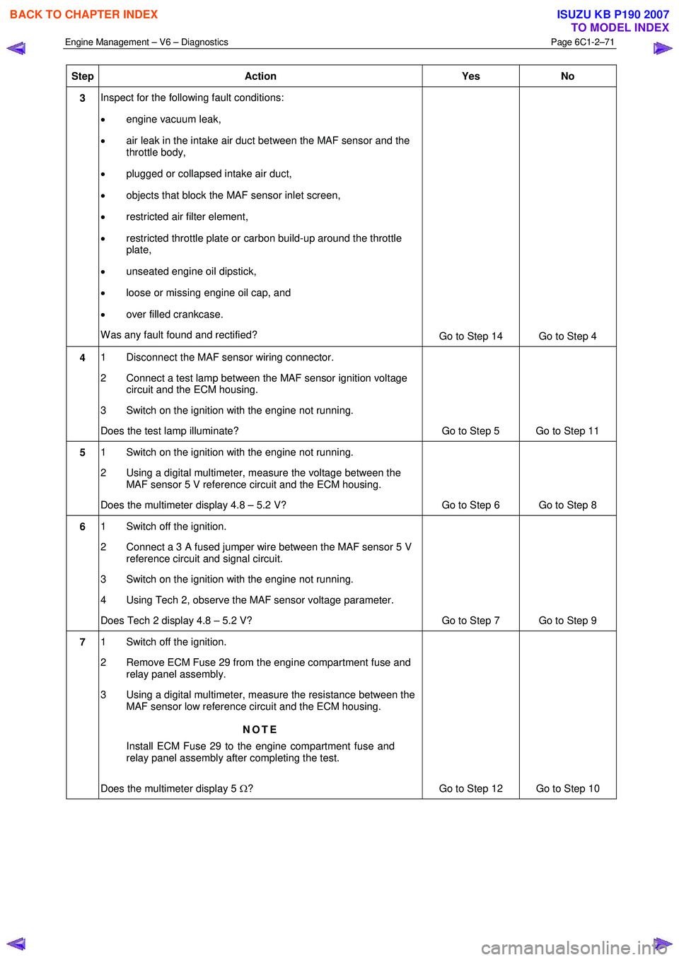
Step Action Yes No
3 Inspect for the following fault conditions:
• engine vacuum leak,
• air leak in the intake air duct between the MAF sensor and the
throttle body,
• plugged or collapsed intake air duct,
• objects that block the MAF sensor inlet screen,
• restricted air filter element,
• restricted throttle plate or carbon build-up around the throttle
plate,
• unseated engine oil dipstick,
• loose or missing engine oil cap, and
• over filled crankcase.
W as any fault found and rectified? Go to Step 14 Go to Step 4
4 1 Disconnect the MAF sensor wiring connector.
2 Connect a test lamp between the MAF sensor ignition voltage circuit and the ECM housing.
3 Switch on the ignition with the engine not running.
Does the test lamp illuminate? Go to Step 5 Go to Step 11
5 1 Switch on the ignition with the engine not running.
2 Using a digital multimeter, measure the voltage between the MAF sensor 5 V reference circuit and the ECM housing.
Does the multimeter display 4.8 – 5.2 V? Go to Step 6 Go to Step 8
6 1 Switch off the ignition.
2 Connect a 3 A fused jumper wire between the MAF sensor 5 V reference circuit and signal circuit.
3 Switch on the ignition with the engine not running.
4 Using Tech 2, observe the MAF sensor voltage parameter.
Does Tech 2 display 4.8 – 5.2 V? Go to Step 7 Go to Step 9
7 1 Switch off the ignition.
2 Remove ECM Fuse 29 from the engine compartment fuse and relay panel assembly.
3 Using a digital multimeter, measure the resistance between the MAF sensor low reference circuit and the ECM housing.
NOTE
Install ECM Fuse 29 to the engine compartment fuse and
relay panel assembly after completing the test.
Does the multimeter display 5 Ω? Go to Step 12 Go to Step 10
BACK TO CHAPTER INDEX
TO MODEL INDEX
ISUZU KB P190 2007
Page 3522 of 6020
Engine Management – V6 – Diagnostics Page 6C1-2–244
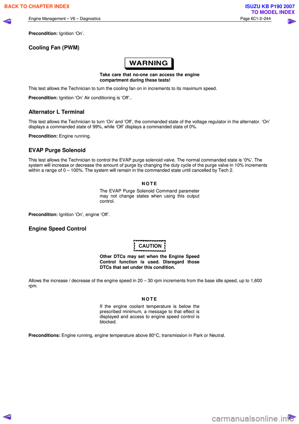
Precondition: Ignition ‘On’.
Cooling Fan (PWM)
Take care that no-one can access the engine
compartment during these tests!
This test allows the Technician to turn the cooling fan on in increments to its maximum speed.
Precondition: Ignition ‘On’ Air conditioning is ‘Off’..
Alternator L Terminal
This test allows the Technician to turn ‘On’ and ‘Off’, the commanded state of the voltage regulator in the alternator. ‘On’
displays a commanded state of 99%, while ‘Off’ displays a commanded state of 0%.
Precondition: Engine running.
EVAP Purge Solenoid
This test allows the Technician to control the EVAP purge solenoid valve. The normal commanded state is ‘0%’. The
system will increase or decrease the amount of purge by changing the duty cycle of the purge valve in 10% increments
within a range of 0 – 100%. The system will remain in the commanded state until cancelled by Tech 2.
NOTE
The EVAP Purge Solenoid Command parameter
may not change states when using this output
control.
Precondition: Ignition ‘On’, engine ‘Off’.
Engine Speed Control
Other DTCs may set when the Engine Speed
Control function is used. Disregard those
DTCs that set under this condition.
Allows the increase / decrease of the engine speed in 20 – 30 rpm increments from the base idle speed, up to 1,600
rpm.
NOTE
If the engine coolant temperature is below the
prescribed minimum, a message to that effect is
displayed and access to engine speed control is
blocked.
Preconditions: Engine running, engine temperature above 80 °C, transmission in Park or Neutral.
BACK TO CHAPTER INDEX
TO MODEL INDEX
ISUZU KB P190 2007
Page 3526 of 6020
Engine Management – V6 – Service Operations Page 6C1-3–2
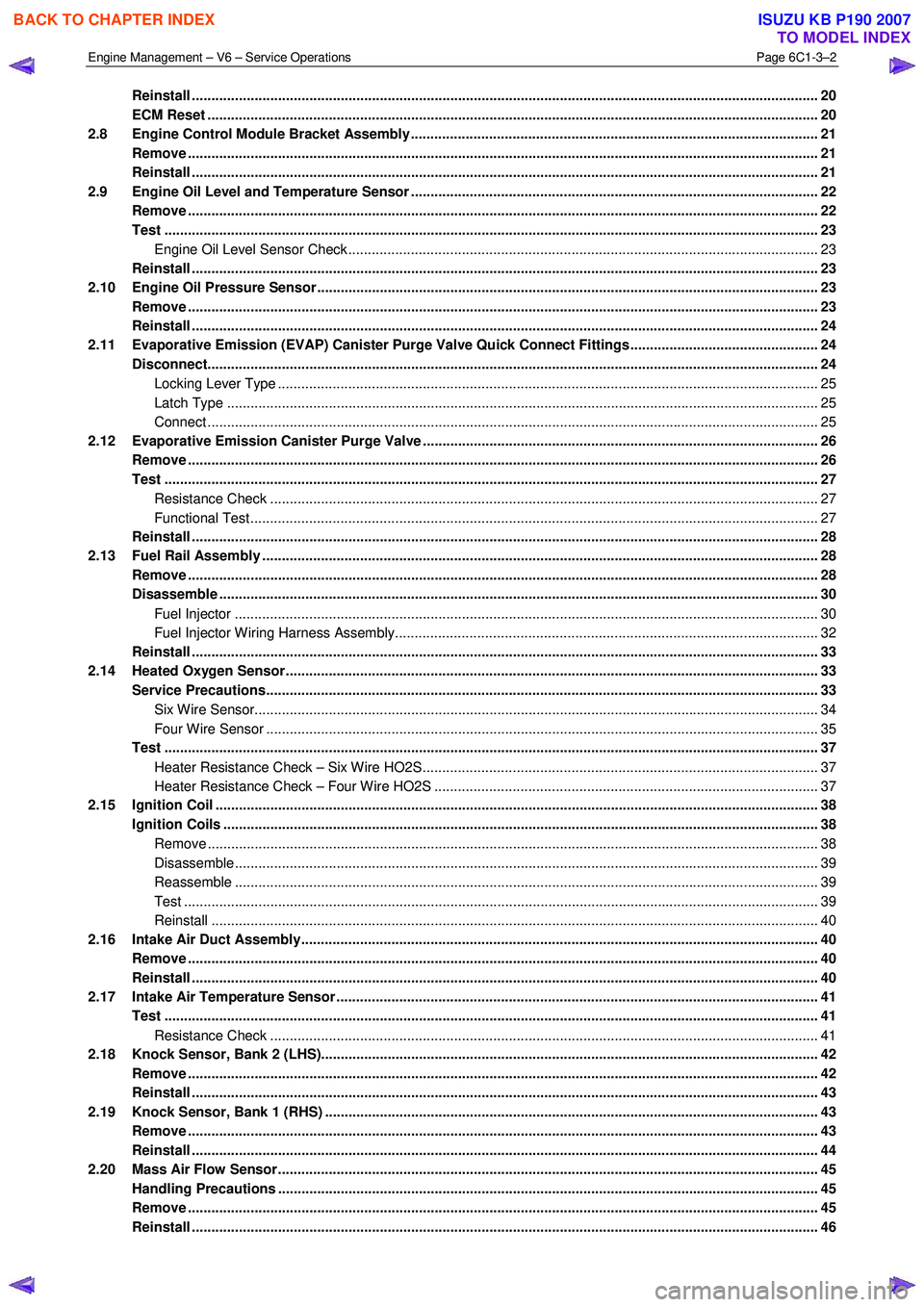
Reinstall ................................................................................................................................................................ 20
ECM Reset ...................................................................................................................... ...................................... 20
2.8 Engine Control Module Bracket Assembly......................................................................................... ............... 21
Remove ................................................................................................................................................................. 21
Reinstall ................................................................................................................................................................ 21
2.9 Engine Oil Level and Temperature Sensor ........................................................................................ ................ 22
Remove ................................................................................................................................................................. 22
Test ....................................................................................................................................................................... 23
Engine Oil Level Sensor Check .................................................................................................. ...................... 23
Reinstall ................................................................................................................................................................ 23
2.10 Engine Oil Pressure Sensor..................................................................................................... ........................... 23
Remove ................................................................................................................................................................. 23
Reinstall ................................................................................................................................................................ 24
2.11 Evaporative Emission (EVAP) Canister Purge Valve Quick Connect Fittings ................................................ 24
Disconnect..................................................................................................................... ....................................... 24
Locking Lever Type ............................................................................................................. ............................. 25
Latch Type ....................................................................................................................................................... 25
Connect ............................................................................................................................................................ 25
2.12 Evaporative Emission Canister Purge Valve ...................................................................................... ............... 26
Remove ................................................................................................................................................................. 26
Test ....................................................................................................................................................................... 27
Resistance Check ............................................................................................................... ............................. 27
Functional Test................................................................................................................................................. 27
Reinstall ................................................................................................................................................................ 28
2.13 Fuel Rail Assembly ............................................................................................................. ................................. 28
Remove ................................................................................................................................................................. 28
Disassemble ......................................................................................................................................................... 30
Fuel Injector ..................................................................................................................................................... 30
Fuel Injector Wiring Harness Assembly.......................................................................................... .................. 32
Reinstall ................................................................................................................................................................ 33
2.14 Heated Oxygen Sensor........................................................................................................... ............................. 33
Service Precautions............................................................................................................................................. 33
Six Wire Sensor................................................................................................................................................ 34
Four Wire Sensor ............................................................................................................... .............................. 35
Test ....................................................................................................................................................................... 37
Heater Resistance Check – Six Wire HO2S........................................................................................ ............. 37
Heater Resistance Check – Four Wire HO2S ....................................................................................... ........... 37
2.15 Ignition Coil .......................................................................................................................................................... 38
Ignition Coils ................................................................................................................. ....................................... 38
Remove ............................................................................................................................................................ 38
Disassemble..................................................................................................................................................... 39
Reassemble ..................................................................................................................................................... 39
Test .................................................................................................................................................................. 39
Reinstall ........................................................................................................................................................... 40
2.16 Intake Air Duct Assembly....................................................................................................... ............................. 40
Remove ................................................................................................................................................................. 40
Reinstall ................................................................................................................................................................ 40
2.17 Intake Air Temperature Sensor .................................................................................................. ......................... 41
Test ....................................................................................................................................................................... 41
Resistance Check ............................................................................................................... ............................. 41
2.18 Knock Sensor, Bank 2 (LHS)..................................................................................................... .......................... 42
Remove ................................................................................................................................................................. 42
Reinstall ................................................................................................................................................................ 43
2.19 Knock Sensor, Bank 1 (RHS) ..................................................................................................... ......................... 43
Remove ................................................................................................................................................................. 43
Reinstall ................................................................................................................................................................ 44
2.20 Mass Air Flow Sensor........................................................................................................... ............................... 45
Handling Precautions .......................................................................................................................................... 45
Remove ................................................................................................................................................................. 45
Reinstall ................................................................................................................................................................ 46
BACK TO CHAPTER INDEX
TO MODEL INDEX
ISUZU KB P190 2007
Page 3535 of 6020
Engine Management – V6 – Service Operations Page 6C1-3–11
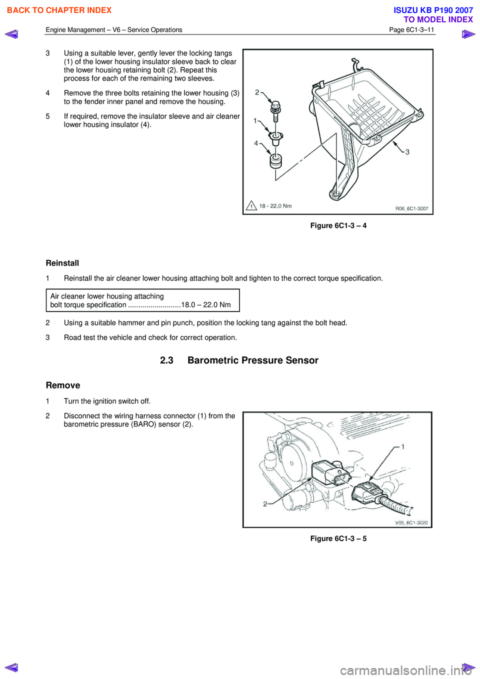
3 Using a suitable lever, gently lever the locking tangs
(1) of the lower housing insulator sleeve back to clear
the lower housing retaining bolt (2). Repeat this
process for each of the remaining two sleeves.
4 Remove the three bolts retaining the lower housing (3) to the fender inner panel and remove the housing.
5 If required, remove the insulator sleeve and air cleaner lower housing insulator (4).
Figure 6C1-3 – 4
Reinstall
1 Reinstall the air cleaner lower housing attaching bolt and tighten to the correct torque specification.
Air cleaner lower housing attaching
bolt torque specification ..........................18.0 – 22.0 Nm
2 Using a suitable hammer and pin punch, position the locking tang against the bolt head.
3 Road test the vehicle and check for correct operation.
2.3 Barometric Pressure Sensor
Remove
1 Turn the ignition switch off.
2 Disconnect the wiring harness connector (1) from the barometric pressure (BARO) sensor (2).
Figure 6C1-3 – 5
BACK TO CHAPTER INDEX
TO MODEL INDEX
ISUZU KB P190 2007
Page 3538 of 6020
Engine Management – V6 – Service Operations Page 6C1-3–14
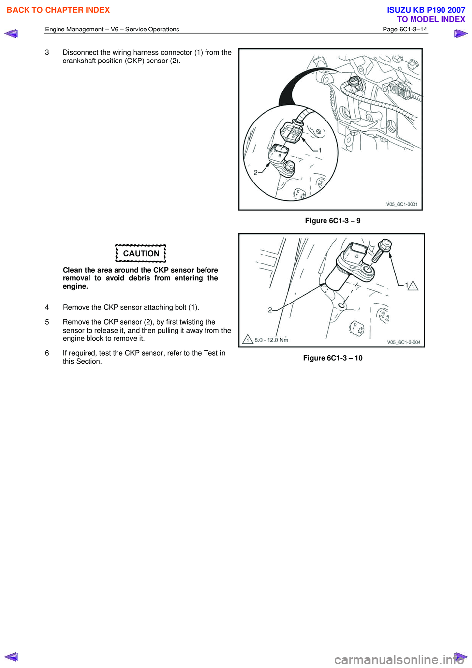
3 Disconnect the wiring harness connector (1) from the
crankshaft position (CKP) sensor (2).
Figure 6C1-3 – 9
Clean the area around the CKP sensor before
removal to avoid debris from entering the
engine.
4 Remove the CKP sensor attaching bolt (1).
5 Remove the CKP sensor (2), by first twisting the sensor to release it, and then pulling it away from the
engine block to remove it.
6 If required, test the CKP sensor, refer to the Test in this Section.
Figure 6C1-3 – 10
BACK TO CHAPTER INDEX
TO MODEL INDEX
ISUZU KB P190 2007
Page 3539 of 6020
Engine Management – V6 – Service Operations Page 6C1-3–15
Test
To prevent component and damage use
connector test adaptor kit J 35616-A.
Resistance Check
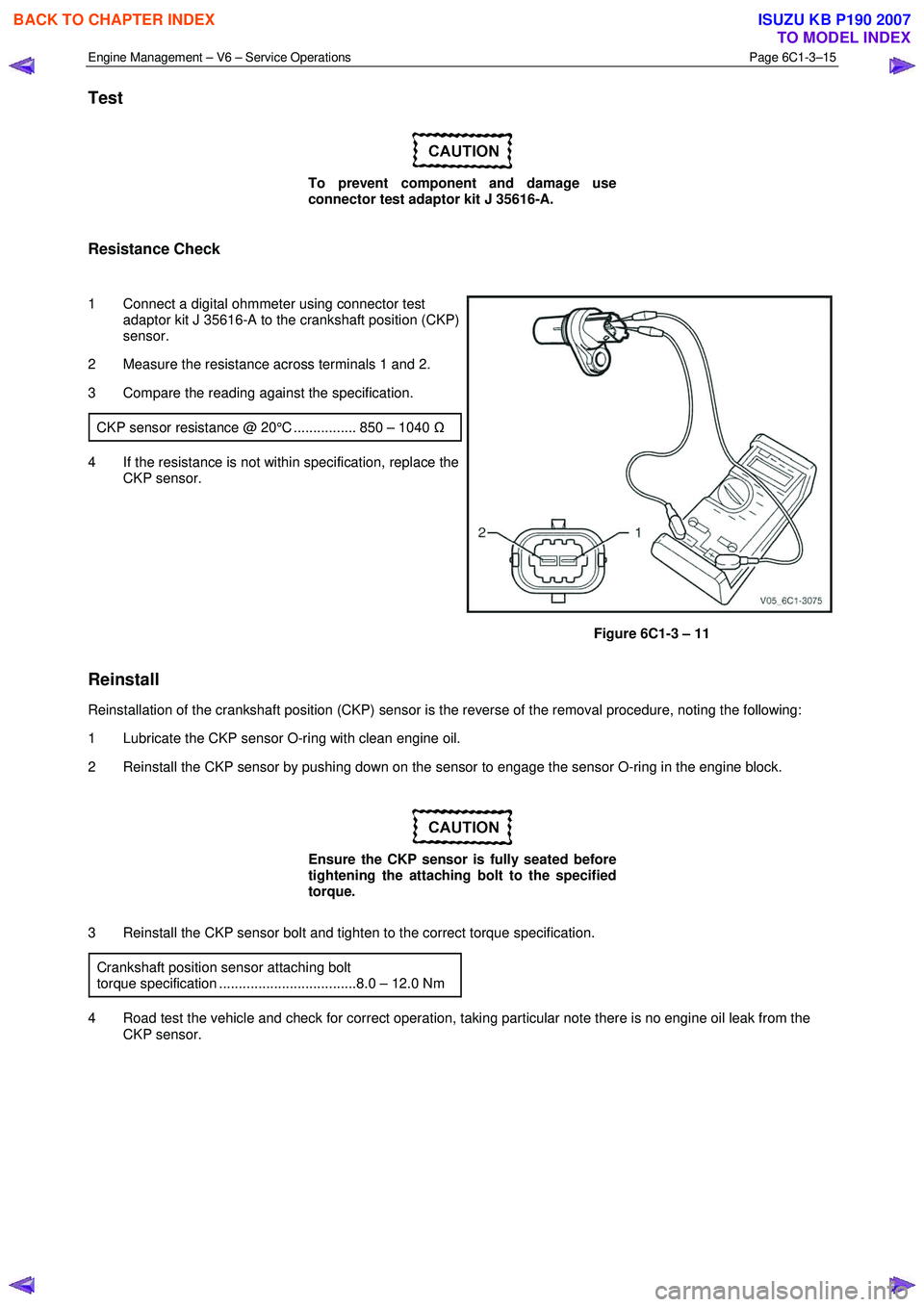
1 Connect a digital ohmmeter using connector test adaptor kit J 35616-A to the crankshaft position (CKP)
sensor.
2 Measure the resistance across terminals 1 and 2.
3 Compare the reading against the specification.
CKP sensor resistance @ 20°C ................ 850 – 1040 Ω
4 If the resistance is not within specification, replace the
CKP sensor.
Figure 6C1-3 – 11
Reinstall
Reinstallation of the crankshaft position (CKP) sensor is the reverse of the removal procedure, noting the following:
1 Lubricate the CKP sensor O-ring with clean engine oil.
2 Reinstall the CKP sensor by pushing down on the sensor to engage the sensor O-ring in the engine block.
Ensure the CKP sensor is fully seated before
tightening the attaching bolt to the specified
torque.
3 Reinstall the CKP sensor bolt and tighten to the correct torque specification. Crankshaft position sensor attaching bolt
torque specification ...................................8.0 – 12.0 Nm
4 Road test the vehicle and check for correct operation, taking particular note there is no engine oil leak from the CKP sensor.
BACK TO CHAPTER INDEX
TO MODEL INDEX
ISUZU KB P190 2007
Page 3543 of 6020
Engine Management – V6 – Service Operations Page 6C1-3–19
Remove
If replacing the ECM, it must be reset prior to
removal. Failure to perform this procedure
will result in the inability to test the ECM for
warranty purposes, refer to ECM Reset in this
Section.
1 Turn the ignition switch off.
2 Disconnect the battery.
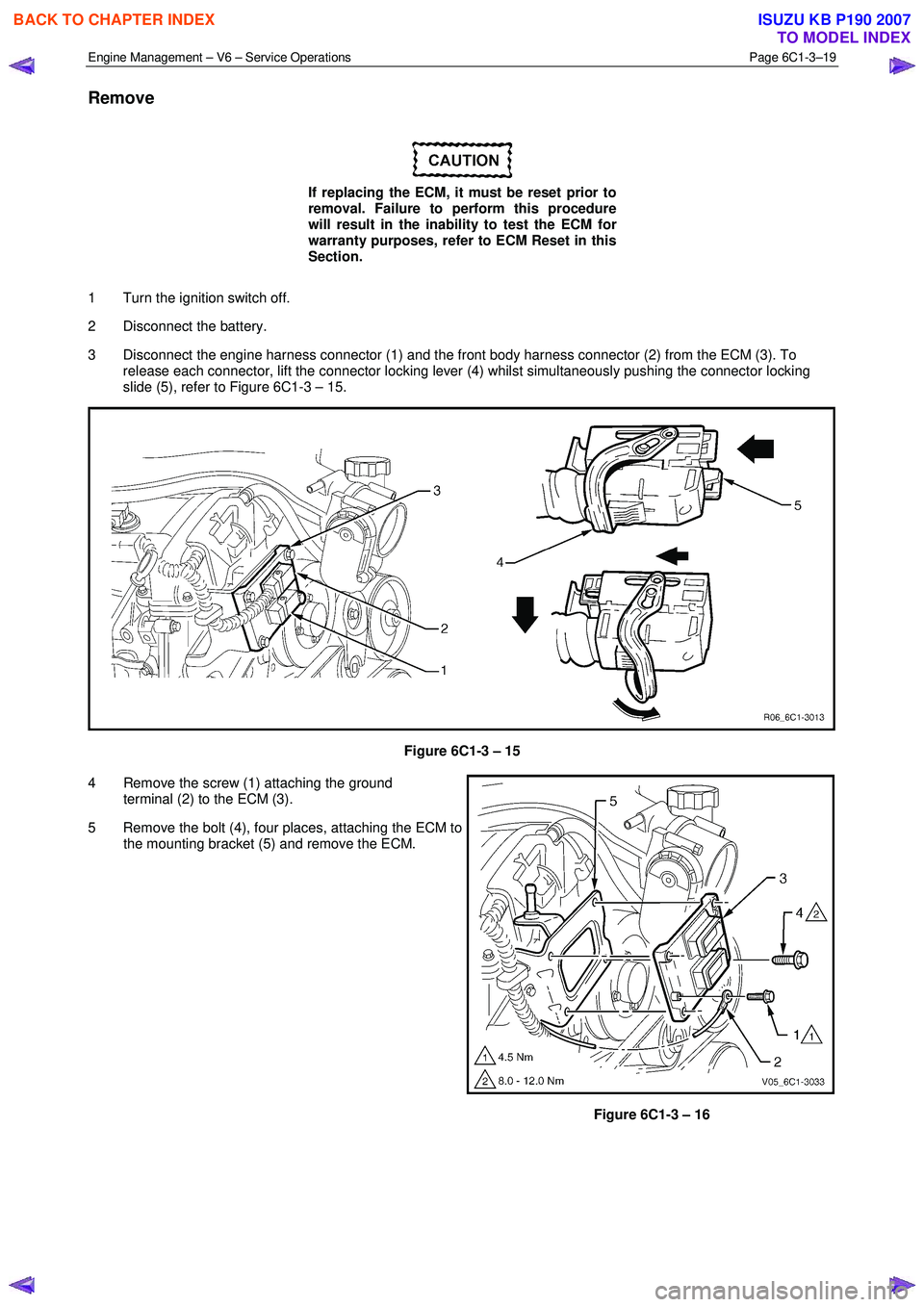
3 Disconnect the engine harness connector (1) and the front body harness connector (2) from the ECM (3). To release each connector, lift the connector locking lever (4) whilst simultaneously pushing the connector locking
slide (5), refer to Figure 6C1-3 – 15.
Figure 6C1-3 – 15
4 Remove the screw (1) attaching the ground terminal (2) to the ECM (3).
5 Remove the bolt (4), four places, attaching the ECM to the mounting bracket (5) and remove the ECM.
Figure 6C1-3 – 16
BACK TO CHAPTER INDEX
TO MODEL INDEX
ISUZU KB P190 2007