2007 ISUZU KB P190 lock
[x] Cancel search: lockPage 3855 of 6020
Automatic Transmission – 4L60E – Electrical Diagnosis Page 7C2–69
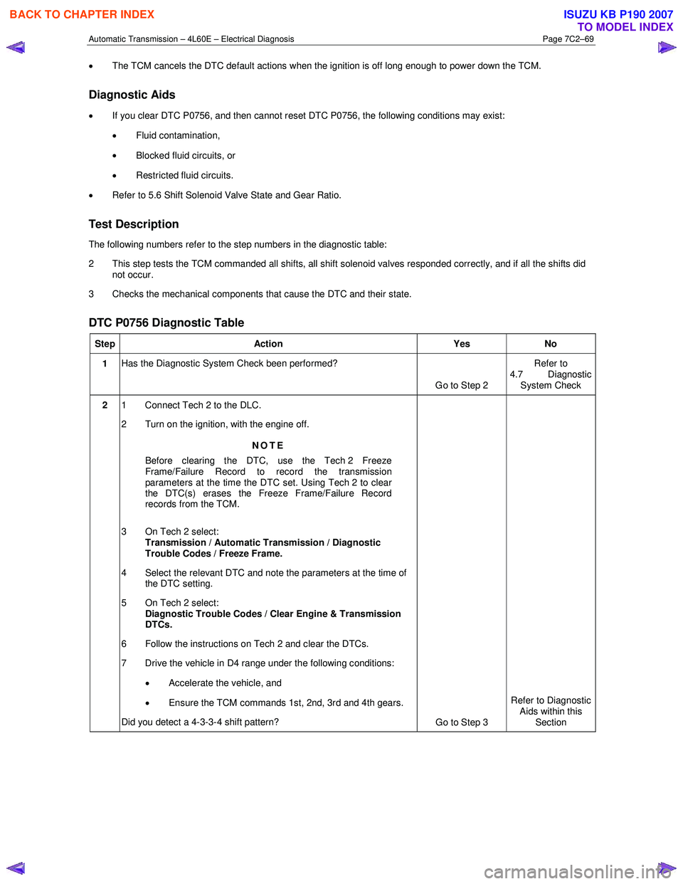
• The TCM cancels the DTC default actions when the ignition is off long enough to power down the TCM.
Diagnostic Aids
•
If you clear DTC P0756, and then cannot reset DTC P0756, the following conditions may exist:
• Fluid contamination,
• Blocked fluid circuits, or
• Restricted fluid circuits.
• Refer to 5.6 Shift Solenoid Valve State and Gear Ratio.
Test Description
The following numbers refer to the step numbers in the diagnostic table:
2 This step tests the TCM commanded all shifts, all shift solenoid valves responded correctly, and if all the shifts did not occur.
3 Checks the mechanical components that cause the DTC and their state.
DTC P0756 Diagnostic Table
Step Action Yes No
1 Has the Diagnostic System Check been performed?
Go to Step 2 Refer to
4.7 Diagnostic System Check
2 1 Connect Tech 2 to the DLC.
2 Turn on the ignition, with the engine off.
NOTE
Before clearing the DTC, use the Tech 2 Freeze
Frame/Failure Record to record the transmission
parameters at the time the DTC set. Using Tech 2 to clear
the DTC(s) erases the Freeze Frame/Failure Record
records from the TCM.
3 On Tech 2 select: Transmission / Automatic Transmission / Diagnostic
Trouble Codes / Freeze Frame.
4 Select the relevant DTC and note the parameters at the time of the DTC setting.
5 On Tech 2 select:
Diagnostic Trouble Codes / Clear Engine & Transmission
DTCs.
6 Follow the instructions on Tech 2 and clear the DTCs.
7 Drive the vehicle in D4 range under the following conditions:
• Accelerate the vehicle, and
• Ensure the TCM commands 1st, 2nd, 3rd and 4th gears.
Did you detect a 4-3-3-4 shift pattern? Go to Step 3 Refer to Diagnostic
Aids within this
Section
BACK TO CHAPTER INDEX
TO MODEL INDEX
ISUZU KB P190 2007
Page 3857 of 6020
Automatic Transmission – 4L60E – Electrical Diagnosis Page 7C2–71
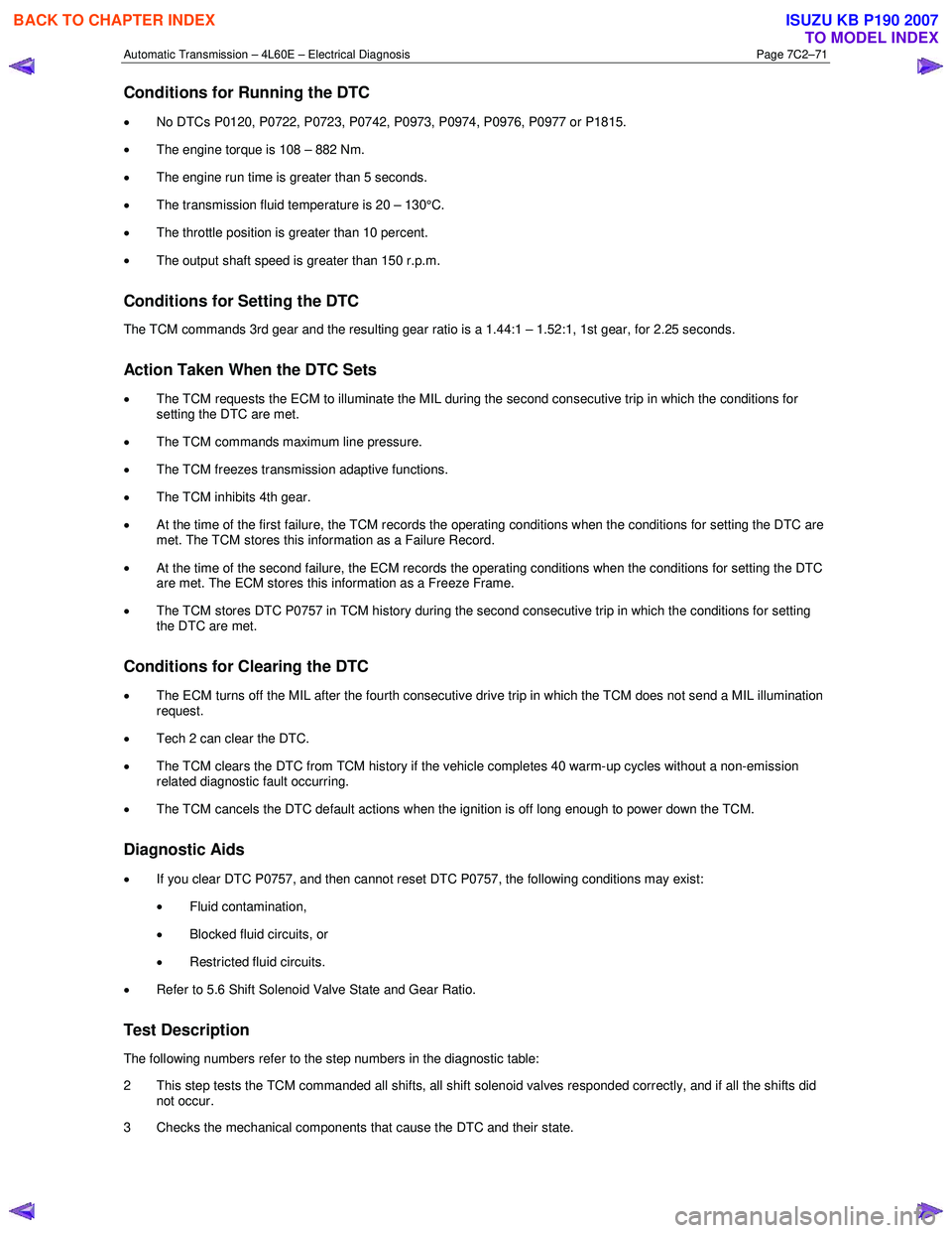
Conditions for Running the DTC
• No DTCs P0120, P0722, P0723, P0742, P0973, P0974, P0976, P0977 or P1815.
• The engine torque is 108 – 882 Nm.
• The engine run time is greater than 5 seconds.
• The transmission fluid temperature is 20 – 130°C.
• The throttle position is greater than 10 percent.
• The output shaft speed is greater than 150 r.p.m.
Conditions for Setting the DTC
The TCM commands 3rd gear and the resulting gear ratio is a 1.44:1 – 1.52:1, 1st gear, for 2.25 seconds.
Action Taken When the DTC Sets
• The TCM requests the ECM to illuminate the MIL during the second consecutive trip in which the conditions for
setting the DTC are met.
• The TCM commands maximum line pressure.
• The TCM freezes transmission adaptive functions.
• The TCM inhibits 4th gear.
• At the time of the first failure, the TCM records the operating conditions when the conditions for setting the DTC are
met. The TCM stores this information as a Failure Record.
• At the time of the second failure, the ECM records the operating conditions when the conditions for setting the DTC
are met. The ECM stores this information as a Freeze Frame.
• The TCM stores DTC P0757 in TCM history during the second consecutive trip in which the conditions for setting
the DTC are met.
Conditions for Clearing the DTC
• The ECM turns off the MIL after the fourth consecutive drive trip in which the TCM does not send a MIL illumination
request.
• Tech 2 can clear the DTC.
• The TCM clears the DTC from TCM history if the vehicle completes 40 warm-up cycles without a non-emission
related diagnostic fault occurring.
• The TCM cancels the DTC default actions when the ignition is off long enough to power down the TCM.
Diagnostic Aids
• If you clear DTC P0757, and then cannot reset DTC P0757, the following conditions may exist:
• Fluid contamination,
• Blocked fluid circuits, or
• Restricted fluid circuits.
• Refer to 5.6 Shift Solenoid Valve State and Gear Ratio.
Test Description
The following numbers refer to the step numbers in the diagnostic table:
2 This step tests the TCM commanded all shifts, all shift solenoid valves responded correctly, and if all the shifts did not occur.
3 Checks the mechanical components that cause the DTC and their state.
BACK TO CHAPTER INDEX
TO MODEL INDEX
ISUZU KB P190 2007
Page 3867 of 6020
Automatic Transmission – 4L60E – Electrical Diagnosis Page 7C2–81
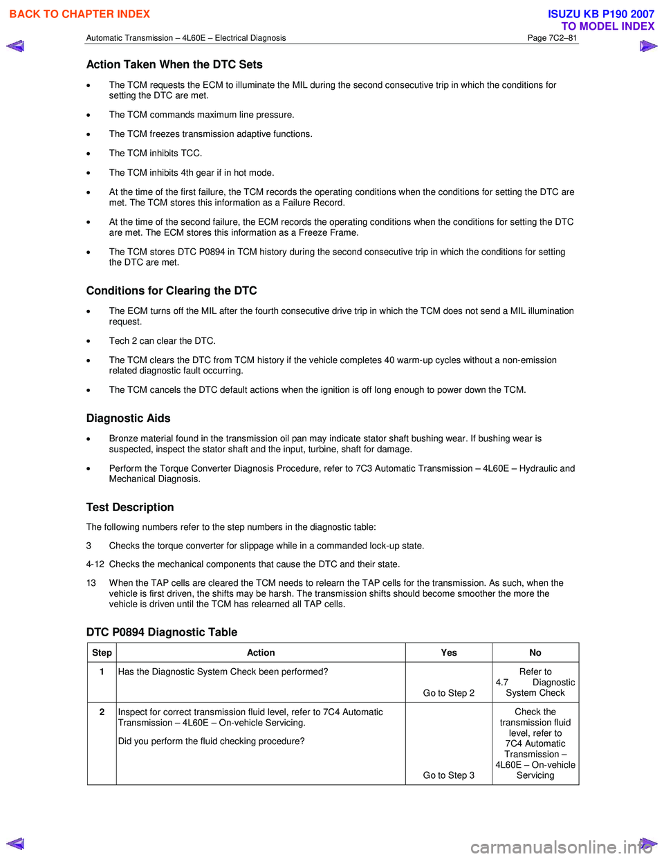
Action Taken When the DTC Sets
• The TCM requests the ECM to illuminate the MIL during the second consecutive trip in which the conditions for
setting the DTC are met.
• The TCM commands maximum line pressure.
• The TCM freezes transmission adaptive functions.
• The TCM inhibits TCC.
• The TCM inhibits 4th gear if in hot mode.
• At the time of the first failure, the TCM records the operating conditions when the conditions for setting the DTC are
met. The TCM stores this information as a Failure Record.
• At the time of the second failure, the ECM records the operating conditions when the conditions for setting the DTC
are met. The ECM stores this information as a Freeze Frame.
• The TCM stores DTC P0894 in TCM history during the second consecutive trip in which the conditions for setting
the DTC are met.
Conditions for Clearing the DTC
• The ECM turns off the MIL after the fourth consecutive drive trip in which the TCM does not send a MIL illumination
request.
• Tech 2 can clear the DTC.
• The TCM clears the DTC from TCM history if the vehicle completes 40 warm-up cycles without a non-emission
related diagnostic fault occurring.
• The TCM cancels the DTC default actions when the ignition is off long enough to power down the TCM.
Diagnostic Aids
•
Bronze material found in the transmission oil pan may indicate stator shaft bushing wear. If bushing wear is
suspected, inspect the stator shaft and the input, turbine, shaft for damage.
• Perform the Torque Converter Diagnosis Procedure, refer to 7C3 Automatic Transmission – 4L60E – Hydraulic and
Mechanical Diagnosis.
Test Description
The following numbers refer to the step numbers in the diagnostic table:
3 Checks the torque converter for slippage while in a commanded lock-up state.
4-12 Checks the mechanical components that cause the DTC and their state.
13 W hen the TAP cells are cleared the TCM needs to relearn the TAP cells for the transmission. As such, when the vehicle is first driven, the shifts may be harsh. The transmission shifts should become smoother the more the
vehicle is driven until the TCM has relearned all TAP cells.
DTC P0894 Diagnostic Table
Step Action Yes No
1 Has the Diagnostic System Check been performed?
Go to Step 2 Refer to
4.7 Diagnostic System Check
2 Inspect for correct transmission fluid level, refer to 7C4 Automatic
Transmission – 4L60E – On-vehicle Servicing.
Did you perform the fluid checking procedure?
Go to Step 3 Check the
transmission fluid level, refer to
7C4 Automatic
Transmission –
4L60E – On-vehicle Servicing
BACK TO CHAPTER INDEX
TO MODEL INDEX
ISUZU KB P190 2007
Page 3870 of 6020
Automatic Transmission – 4L60E – Electrical Diagnosis Page 7C2–84
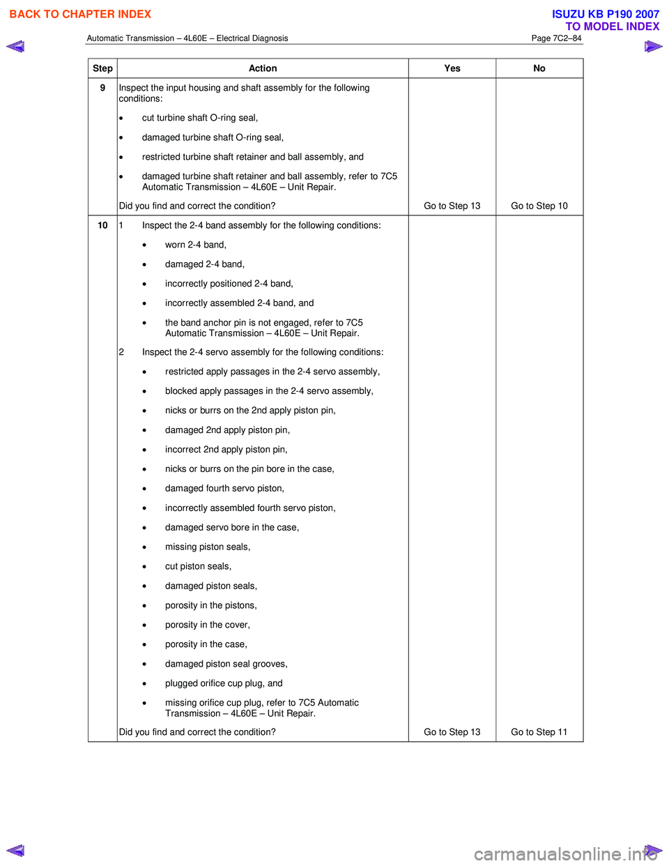
Step Action Yes No
9 Inspect the input housing and shaft assembly for the following
conditions:
• cut turbine shaft O-ring seal,
• damaged turbine shaft O-ring seal,
• restricted turbine shaft retainer and ball assembly, and
• damaged turbine shaft retainer and ball assembly, refer to 7C5
Automatic Transmission – 4L60E – Unit Repair.
Did you find and correct the condition? Go to Step 13 Go to Step 10
10 1 Inspect the 2-4 band assembly for the following conditions:
• worn 2-4 band,
• damaged 2-4 band,
• incorrectly positioned 2-4 band,
• incorrectly assembled 2-4 band, and
• the band anchor pin is not engaged, refer to 7C5
Automatic Transmission – 4L60E – Unit Repair.
2 Inspect the 2-4 servo assembly for the following conditions:
• restricted apply passages in the 2-4 servo assembly,
• blocked apply passages in the 2-4 servo assembly,
• nicks or burrs on the 2nd apply piston pin,
• damaged 2nd apply piston pin,
• incorrect 2nd apply piston pin,
• nicks or burrs on the pin bore in the case,
• damaged fourth servo piston,
• incorrectly assembled fourth servo piston,
• damaged servo bore in the case,
• missing piston seals,
• cut piston seals,
• damaged piston seals,
• porosity in the pistons,
• porosity in the cover,
• porosity in the case,
• damaged piston seal grooves,
• plugged orifice cup plug, and
• missing orifice cup plug, refer to 7C5 Automatic
Transmission – 4L60E – Unit Repair.
Did you find and correct the condition? Go to Step 13 Go to Step 11
BACK TO CHAPTER INDEX
TO MODEL INDEX
ISUZU KB P190 2007
Page 3871 of 6020
Automatic Transmission – 4L60E – Electrical Diagnosis Page 7C2–85
Step Action Yes No
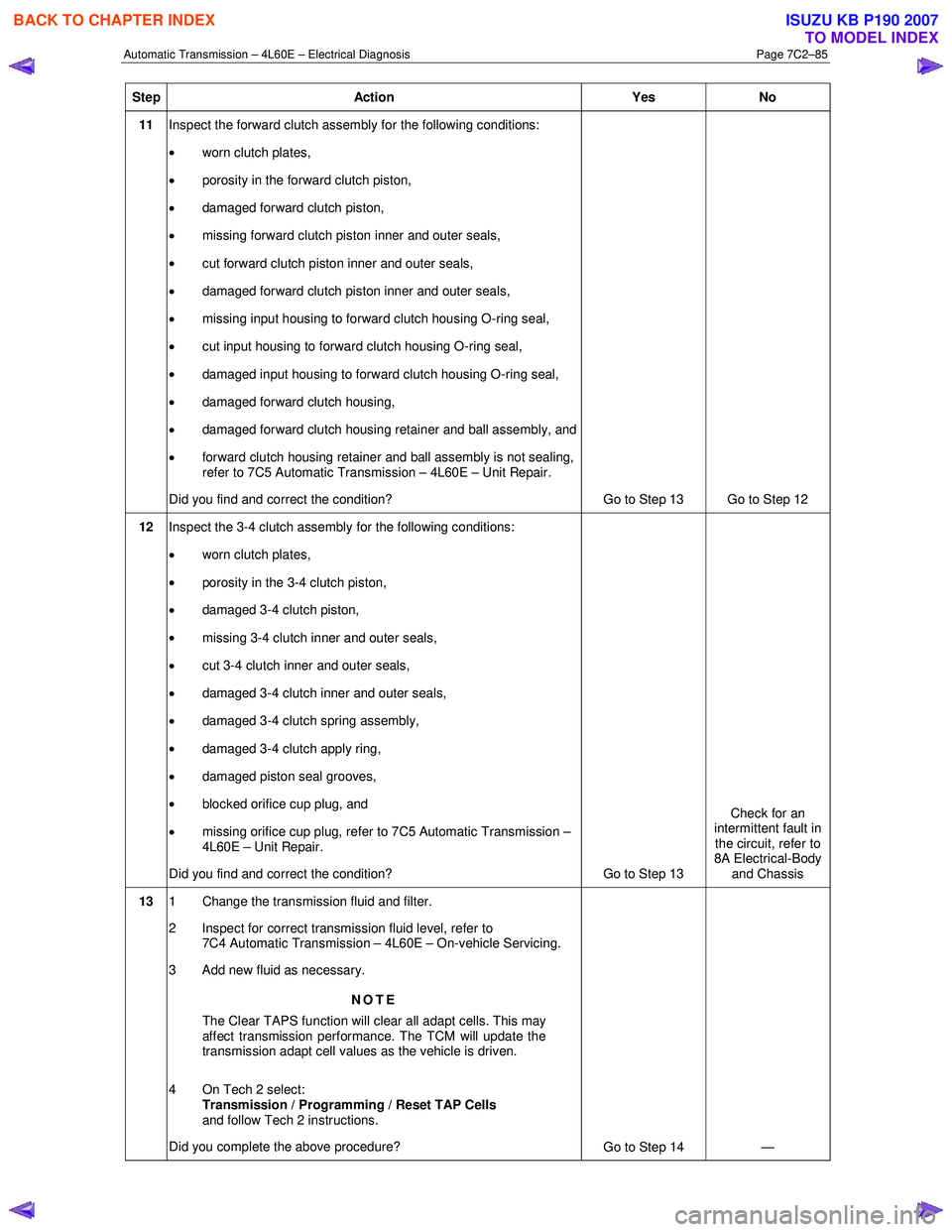
11 Inspect the forward clutch assembly for the following conditions:
• worn clutch plates,
• porosity in the forward clutch piston,
• damaged forward clutch piston,
• missing forward clutch piston inner and outer seals,
• cut forward clutch piston inner and outer seals,
• damaged forward clutch piston inner and outer seals,
• missing input housing to forward clutch housing O-ring seal,
• cut input housing to forward clutch housing O-ring seal,
• damaged input housing to forward clutch housing O-ring seal,
• damaged forward clutch housing,
• damaged forward clutch housing retainer and ball assembly, and
• forward clutch housing retainer and ball assembly is not sealing,
refer to 7C5 Automatic Transmission – 4L60E – Unit Repair.
Did you find and correct the condition? Go to Step 13 Go to Step 12
12 Inspect the 3-4 clutch assembly for the following conditions:
• worn clutch plates,
• porosity in the 3-4 clutch piston,
• damaged 3-4 clutch piston,
• missing 3-4 clutch inner and outer seals,
• cut 3-4 clutch inner and outer seals,
• damaged 3-4 clutch inner and outer seals,
• damaged 3-4 clutch spring assembly,
• damaged 3-4 clutch apply ring,
• damaged piston seal grooves,
• blocked orifice cup plug, and
• missing orifice cup plug, refer to 7C5 Automatic Transmission –
4L60E – Unit Repair.
Did you find and correct the condition? Go to Step 13 Check for an
intermittent fault in the circuit, refer to
8A Electrical-Body and Chassis
13 1 Change the transmission fluid and filter.
2 Inspect for correct transmission fluid level, refer to 7C4 Automatic Transmission – 4L60E – On-vehicle Servicing.
3 Add new fluid as necessary.
NOTE
The Clear TAPS function will clear all adapt cells. This may
affect transmission performance. The TCM will update the
transmission adapt cell values as the vehicle is driven.
4 On Tech 2 select: Transmission / Programming / Reset TAP Cells
and follow Tech 2 instructions.
Did you complete the above procedure? Go to Step 14 —
BACK TO CHAPTER INDEX
TO MODEL INDEX
ISUZU KB P190 2007
Page 3893 of 6020
Automatic Transmission – 4L60E – Electrical Diagnosis Page 7C2–107
Step Action Yes No
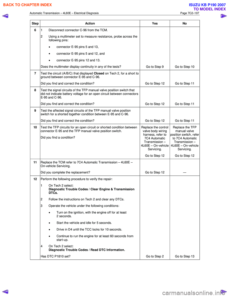
6 1 Disconnect connector C-96 from the TCM.
2 Using a multimeter set to measure resistance, probe across the following pins:
• connector E-95 pins 5 and 13,
• connector E-95 pins 5 and 12, and
• connector E-95 pins 12 and 13.
Does the multimeter display continuity in any of the tests? Go to Step 9 Go to Step 10
7 Test the circuit (A/B/C) that displayed Closed on Tech 2, for a short to
ground between connector E-95 and C-96.
Did you find and correct the condition? Go to Step 12 Go to Step 11
8 Test the signal circuits of the TFP manual valve position switch that
did not indicate battery voltage for an open circuit between connectors
E-95 and C-96.
Did you find and correct the condition? Go to Step 12 Go to Step 11
9 Test the affected signal circuits of the TFP manual valve position
switch for a shorted together condition between E-95 and C-96.
Did you find and correct the condition? Go to Step 12 Go to Step 11
10 Test the TFP circuits for an open circuit or shorted condition between
connector E-95 and the TFP manual valve position switch.
Did you find a condition? Replace the control
valve body wiring harness, refer to
7C4 Automatic
Transmission –
4L60E – On-vehicle Servicing.
Go to Step 12 Replace the TFP
manual valve
position switch, refer
to 7C4 Automatic Transmission –
4L60E – On-vehicle Servicing.
Go to Step 12
11 Replace the TCM refer to 7C4 Automatic Transmission – 4L60E –
On-vehicle Servicing.
Did you complete the replacement? Go to Step 12 —
12 Perform the following procedure to verify the repair:
1 On Tech 2 select: Diagnostic Trouble Codes / Clear Engine & Transmission
DTCs.
2 Follow the instructions on Tech 2 and clear any DTCs.
3 Operate the vehicle under the following conditions:
• Turn on the ignition, with the engine off for at least
2 seconds.
• Start the vehicle and idle for 5 seconds.
• Drive in D4 until the TCC locks for 10 seconds.
• Continue to run the engine for at least 60 seconds from
start-up.
4 On Tech 2 select:
Diagnostic Trouble Codes / Read DTC Information.
Has DTC P1810 set? Go to Step 2 Go to Step 13
BACK TO CHAPTER INDEX
TO MODEL INDEX
ISUZU KB P190 2007
Page 3919 of 6020

Automatic Transmission – 4L60E – On-vehicle Servicing Page 7C4–6
6 Lift the locking lever (1) on the transmission fluid
indicator, then remove the indicator from the filler
tube (2) and check the fluid colour, condition and level.
Do not overfill the transmission. Overfilling
can cause aeration resulting in fluid loss,
shift complaints and possible damage to the
transmission.
7 If the transmission fluid level is low, add only enough of the recommended fluid until
its level shows onto the
crosshatch hot area (3) of the fluid indicator.
Figure 7C4 – 1
2.2 Reverse Flush and Flow Rate Test
It is essential to perform a reverse flush and oil cooler flow rate test after any of the following:
• the transmission is repaired or replaced,
• fluid contamination is suspected, or
• whenever the oil pump and/or torque converter is replaced.
NOTE
The reverse flush must be completed prior to
conducting a flow rate test.
Reverse Flush
1 Disconnect both cooler hose/line assemblies at the transmission and at the radiator cooler, refer to 3.17 Transmission Cooler Line/Hose Assemblies.
2 Check the cooler hose/line to radiator cooler fittings for damage, replace as required.
To avoid personal injury, wear safety glasses
when using compressed air.
3 Carefully check the radiator cooler lower fitting to see if any foreign material is evident at this point. If foreign material is found, remove it with a suitable tool and/or compressed air at a reduced pressure of approximately
345 kPa blown in the reverse direction through the cooler.
4 Using compressed air at a reduced pressure of approximately 345 kPa blown in a reverse direction, clean the cooler hose/line assemblies.
5 Reconnect the cooler outlet line to the transmission and both cooler hose/line assemblies to the radiator cooler fittings, refer to 3.17 Transmission Cooler Line/Hose Assemblies.
NOTE
Do not reconnect the cooler inlet line at the
transmission end. This line needs to be left
disconnected to perform the flow rate test.
6 Perform the flow rate test, refer to Flow Rate Test in this Section.
BACK TO CHAPTER INDEX
TO MODEL INDEX
ISUZU KB P190 2007
Page 3925 of 6020
Automatic Transmission – 4L60E – On-vehicle Servicing Page 7C4–12
4 Remove the knob together with the button (5) and spring (6) from the selector lever assembly (7).
5 Turn the sleeve (8) counter clockwise to remove it, make note of the number of turns required to free it.
6 Remove the harness connectors from the base plate (9).
7 Remove the upper housing (10) which is held in place by four latched fasteners.
8 Remove the attaching screw (11) and spring plate (12).
9 Remove the grooved pin (13).
10 Using a small flat blade screwdriver, gently prise the upper end of the selector cable (14) from the pin on the selector lever linkage (15).
11 Remove the selector lever assembly by pressing the rod down (lever in the N position).
12 If required, remove the lamp (16) from its socket by aligning the groove in the socket and the protruding part of the lamp.
13 If required, remove the nut (17), four places, and the shift selector base plate.
Reinstall
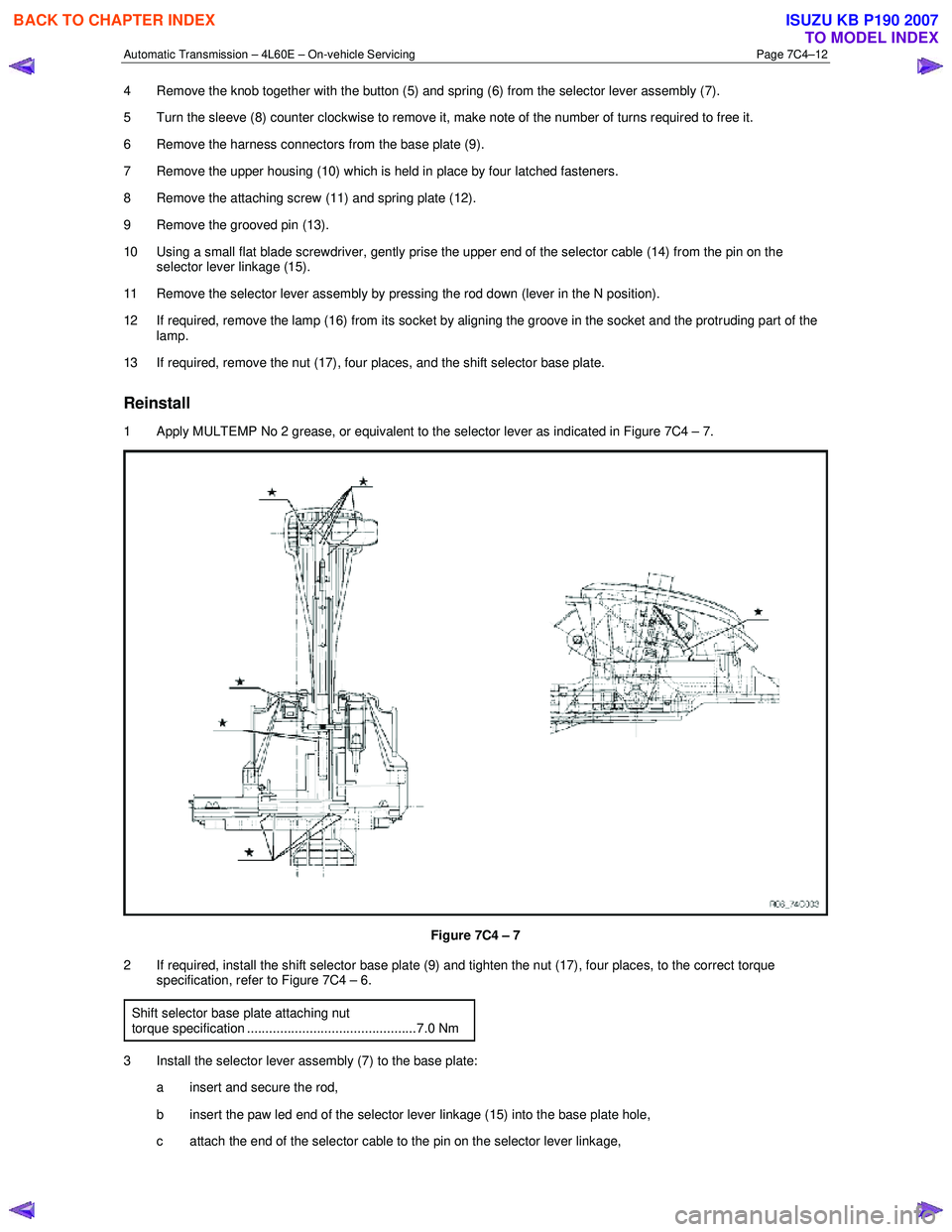
1 Apply MULTEMP No 2 grease, or equivalent to the selector lever as indicated in Figure 7C4 – 7.
Figure 7C4 – 7
2 If required, install the shift selector base plate (9) and tighten the nut (17), four places, to the correct torque specification, refer to Figure 7C4 – 6.
Shift selector base plate attaching nut
torque specification ..............................................7.0 Nm
3 Install the selector lever assembly (7) to the base plate: a insert and secure the rod,
b insert the paw led end of the selector lever linkage (15) into the base plate hole,
c attach the end of the selector cable to the pin on the selector lever linkage,
BACK TO CHAPTER INDEX
TO MODEL INDEX
ISUZU KB P190 2007