2007 ISUZU KB P190 engine
[x] Cancel search: enginePage 1366 of 6020
6A-6 ENGINE MECHANICAL (4JK1/4JJ1)
• Insert a 0.15 mm (0.006 in) thickness gauge
between the roller of the rocker arm and the
camshaft to tighten up the adjusting screw o
f
the rocker arm. W hen the movement of the
thickness gauge becomes tight, fasten the
adjusting screw nut of the rocker arm.
Valve clearance mm (in)
Intake valve 0.15 (0.006)
Exhaust valve 0.15 (0.006)
Note:
Adjust while cold.
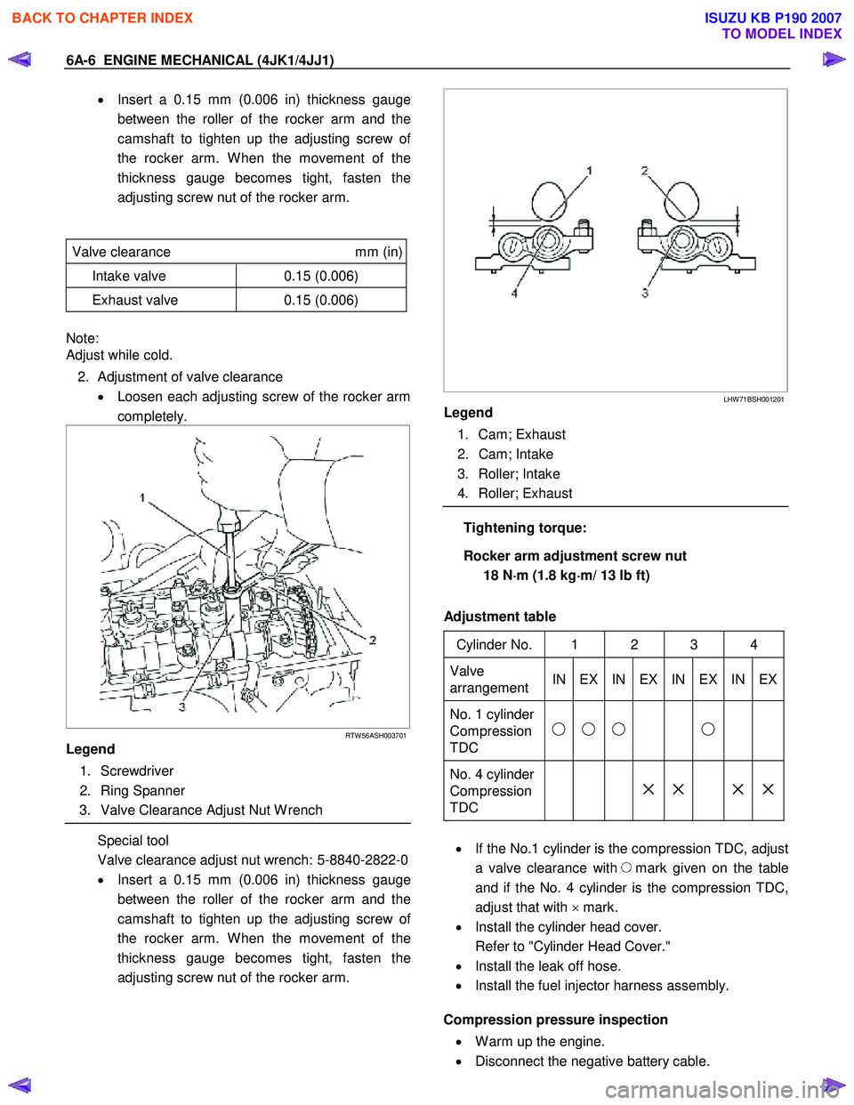
2. Adjustment of valve clearance • Loosen each adjusting screw of the rocker arm
completely.
RTW 56ASH003701
Legend
1. Screwdriver
2. Ring Spanner
3. Valve Clearance Adjust Nut W rench
Special tool
Valve clearance adjust nut wrench: 5-8840-2822-0
• Insert a 0.15 mm (0.006 in) thickness gauge
between the roller of the rocker arm and the
camshaft to tighten up the adjusting screw o
f
the rocker arm. W hen the movement of the
thickness gauge becomes tight, fasten the
adjusting screw nut of the rocker arm.
LHW 71BSH001201
Legend
1. Cam; Exhaust
2. Cam; Intake
3. Roller; Intake
4. Roller; Exhaust
Tightening torque:
Rocker arm adjustment screw nut 18 N ⋅
⋅⋅
⋅
m (1.8 kg ⋅
⋅⋅
⋅
m/ 13 lb ft)
Adjustment table
Cylinder No. 1 2 3 4
Valve
arrangement IN EX IN EX IN EX IN EX
No. 1 cylinder
Compression
TDC
No. 4 cylinder
Compression
TDC
× × × ×
• If the No.1 cylinder is the compression TDC, adjust
a valve clearance with
mark given on the table
and if the No. 4 cylinder is the compression TDC,
adjust that with × mark.
• Install the cylinder head cover.
Refer to "Cylinder Head Cover."
• Install the leak off hose.
• Install the fuel injector harness assembly.
Compression pressure inspection
• W arm up the engine.
• Disconnect the negative battery cable.
BACK TO CHAPTER INDEX
TO MODEL INDEX
ISUZU KB P190 2007
Page 1367 of 6020
ENGINE MECHANICAL (4JK1/4JJ1) 6A-7
• Remove the all glow plugs.
Note:
W hen the harness connector is removed, ECM judges
that it broke down and DTC is recorded. Upon
completion of measurement, never fail to clear the
memory of the ECM.
(For how to clear the memory of the ECM, refer to
“ENGINE CONTROL SYSTEM” Section)
• Connect the negative battery cable.
• Turn on the starter to emit foreign matter within the
cylinders.
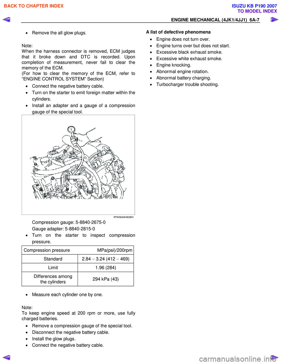
• Install an adapter and a gauge of a compression
gauge of the special tool.
RTW 56ASH003801
Compression gauge: 5-8840-2675-0
Gauge adapter: 5-8840-2815-0
• Turn on the starter to inspect compression
pressure.
Compression pressure MPa(psi)/200rpm
Standard 2.84 − 3.24 (412 − 469)
Limit 1.96 (284)
Differences among
the cylinders 294 kPa (43)
•
Measure each cylinder one by one.
Note:
To keep engine speed at 200 rpm or more, use full
y
charged batteries.
• Remove a compression gauge of the special tool.
• Disconnect the negative battery cable.
• Install the glow plugs.
• Connect the negative battery cable.
A list of defective phenomena
• Engine does not turn over.
• Engine turns over but does not start.
• Excessive black exhaust smoke.
• Excessive white exhaust smoke.
• Engine knocking.
• Abnormal engine rotation.
• Abnormal battery charging.
• Turbocharger trouble shooting.
BACK TO CHAPTER INDEX
TO MODEL INDEX
ISUZU KB P190 2007
Page 1368 of 6020
6A-8 ENGINE MECHANICAL (4JK1/4JJ1)
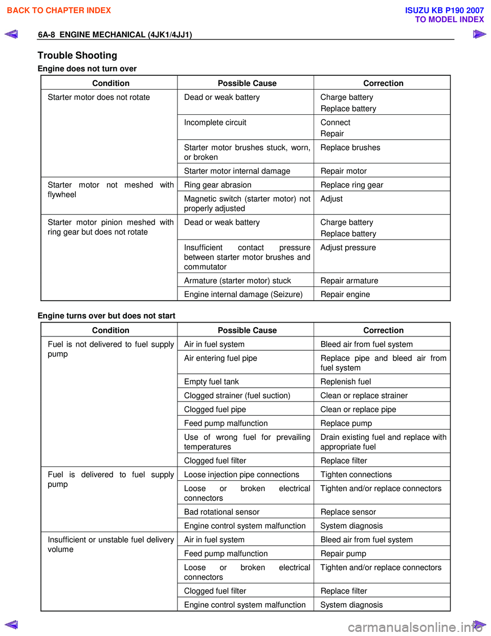
Trouble Shooting
Engine does not turn over
Condition Possible Cause Correction
Dead or weak battery Charge battery
Replace battery
Incomplete circuit Connect
Repair
Starter motor brushes stuck, worn,
or broken Replace brushes
Starter motor does not rotate
Starter motor internal damage Repair motor
Ring gear abrasion Replace ring gear Starter motor not meshed with
flywheel Magnetic switch (starter motor) not
properly adjusted Adjust
Dead or weak battery
Charge battery
Replace battery
Insufficient contact pressure
between starter motor brushes and
commutator Adjust pressure
Armature (starter motor) stuck Repair armature
Starter motor pinion meshed with
ring gear but does not rotate
Engine internal damage (Seizure) Repair engine
Engine turns over but does not start
Condition Possible Cause Correction
Air in fuel system Bleed air from fuel system
Air entering fuel pipe Replace pipe and bleed air from
fuel system
Empty fuel tank Replenish fuel
Clogged strainer (fuel suction) Clean or replace strainer
Clogged fuel pipe Clean or replace pipe
Feed pump malfunction Replace pump
Use of wrong fuel for prevailing
temperatures Drain existing fuel and replace with
appropriate fuel
Fuel is not delivered to fuel supply
pump
Clogged fuel filter Replace filter
Loose injection pipe connections Tighten connections
Loose or broken electrical
connectors Tighten and/or replace connectors
Bad rotational sensor
Replace sensor
Fuel is delivered to fuel supply
pump
Engine control system malfunction System diagnosis
Air in fuel system Bleed air from fuel system
Feed pump malfunction Repair pump
Loose or broken electrical
connectors Tighten and/or replace connectors
Clogged fuel filter
Replace filter
Insufficient or unstable fuel delivery
volume
Engine control system malfunction System diagnosis
BACK TO CHAPTER INDEX
TO MODEL INDEX
ISUZU KB P190 2007
Page 1369 of 6020

ENGINE MECHANICAL (4JK1/4JJ1) 6A-9
Excessive black exhaust smoke
Condition Possible Cause Correction
Bad injection timing Engine control system malfunction System diagnosis
Carbon deposit at nozzle tip Clean fuel injector assembly
Sticking nozzle Replace fuel injector assembly
Bad fuel injector condition
Engine control system malfunction System diagnosis
Excessive valve clearance Adjust clearance
Sticking valve stem (valve open) Repair or replace valve
Damaged valve spring Replace spring
Valve seat abrasion Repair valve seat
Compression leakage due to
damaged piston ring Replace piston ring
Damaged gasket
Replace gasket
Insufficient compression pressure
Piston scoring Replace piston
W ater in fuel Drain existing fuel and replace with
new fuel Fuel condition
Poor fuel quality Drain existing fuel and replace with
new fuel
Clogged intake pipes Clean or replace pipes Poor engine aspiration
Clogged air cleaner element Clean or replace element
Defective sensor Replace sensor Malfunction detected by engine
control system Engine control system malfunction System diagnosis
Intake throttle valve sticking Repair or replace valve
EGR valve sticking Repair or replace valve
EGR valve and/or intake throttle
valve malfunction
Engine control system malfunction System diagnosis
Damaged turbocharger blade Replace turbocharger
Rough turbocharger shaft rotation Replace turbocharger
Oil leakage from oil seal Replace turbocharger
Turbocharger malfunction
Broken actuator Replace turbocharger
BACK TO CHAPTER INDEX
TO MODEL INDEX
ISUZU KB P190 2007
Page 1370 of 6020
6A-10 ENGINE MECHANICAL (4JK1/4JJ1)
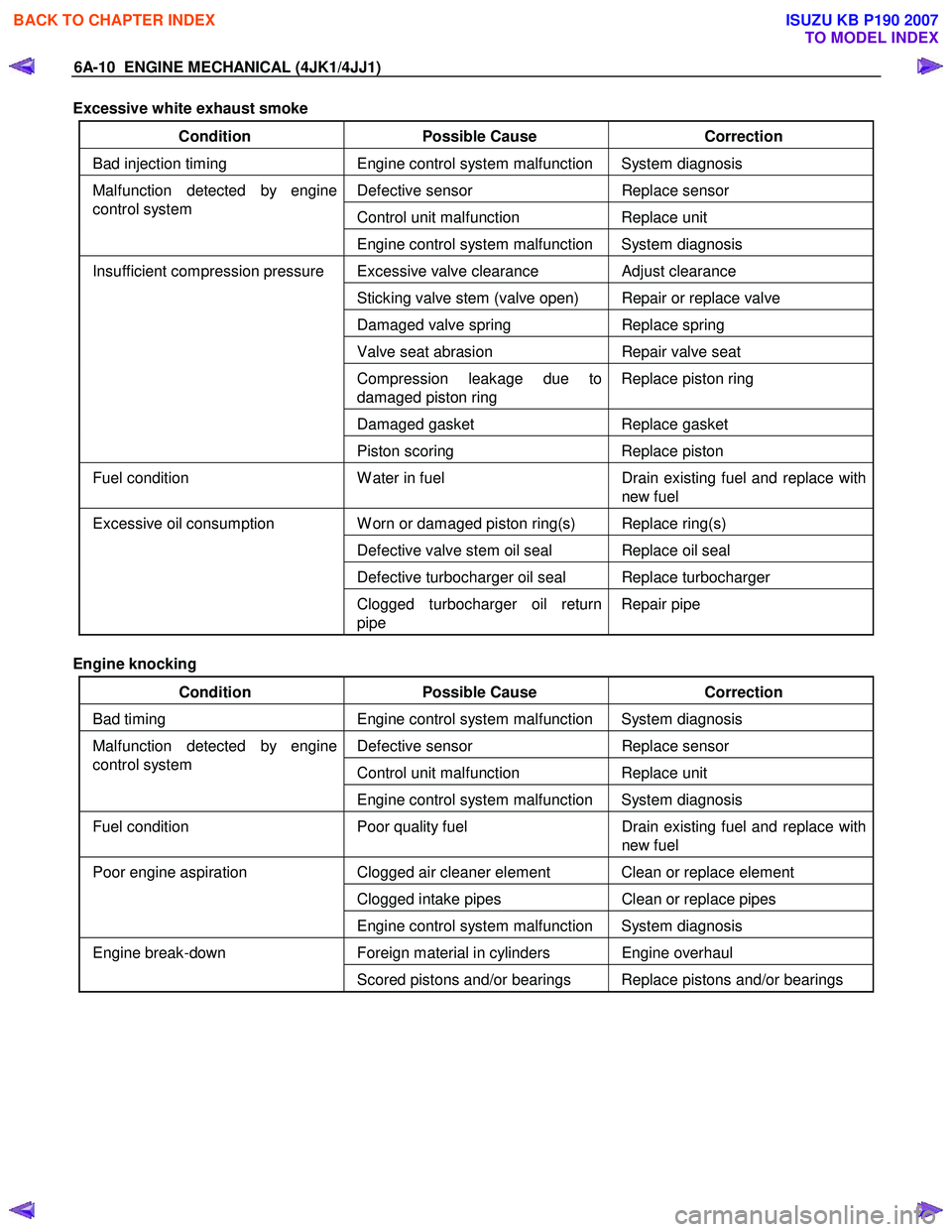
Excessive white exhaust smoke
Condition Possible Cause Correction
Bad injection timing Engine control system malfunction System diagnosis
Defective sensor Replace sensor
Control unit malfunction Replace unit
Malfunction detected by engine
control system
Engine control system malfunction System diagnosis
Excessive valve clearance Adjust clearance
Sticking valve stem (valve open) Repair or replace valve
Damaged valve spring Replace spring
Valve seat abrasion Repair valve seat
Compression leakage due to
damaged piston ring Replace piston ring
Damaged gasket
Replace gasket
Insufficient compression pressure
Piston scoring Replace piston
Fuel condition W ater in fuel Drain existing fuel and replace with
new fuel
W orn or damaged piston ring(s) Replace ring(s)
Defective valve stem oil seal Replace oil seal
Defective turbocharger oil seal Replace turbocharger
Excessive oil consumption
Clogged turbocharger oil return
pipe Repair pipe
Engine knocking
Condition Possible Cause Correction
Bad timing Engine control system malfunction System diagnosis
Defective sensor Replace sensor
Control unit malfunction Replace unit
Malfunction detected by engine
control system
Engine control system malfunction System diagnosis
Fuel condition Poor quality fuel Drain existing fuel and replace with
new fuel
Clogged air cleaner element Clean or replace element
Clogged intake pipes Clean or replace pipes
Poor engine aspiration
Engine control system malfunction System diagnosis
Foreign material in cylinders Engine overhaul Engine break-down Scored pistons and/or bearings Replace pistons and/or bearings
BACK TO CHAPTER INDEX
TO MODEL INDEX
ISUZU KB P190 2007
Page 1371 of 6020
ENGINE MECHANICAL (4JK1/4JJ1) 6A-11
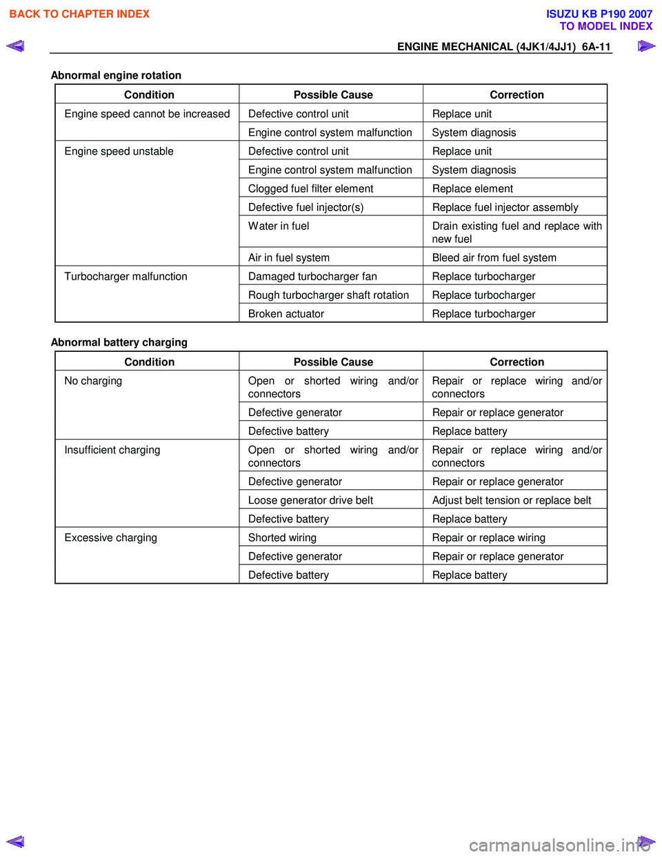
Abnormal engine rotation
Condition Possible Cause Correction
Defective control unit Replace unit Engine speed cannot be increased
Engine control system malfunction System diagnosis
Defective control unit Replace unit
Engine control system malfunction System diagnosis
Clogged fuel filter element Replace element
Defective fuel injector(s) Replace fuel injector assembly
W ater in fuel Drain existing fuel and replace with
new fuel
Engine speed unstable
Air in fuel system Bleed air from fuel system
Damaged turbocharger fan Replace turbocharger
Rough turbocharger shaft rotation Replace turbocharger
Turbocharger malfunction
Broken actuator Replace turbocharger
Abnormal battery charging
Condition Possible Cause Correction
Open or shorted wiring and/or
connectors Repair or replace wiring and/or
connectors
Defective generator Repair or replace generator
No charging
Defective battery Replace battery
Open or shorted wiring and/or
connectors Repair or replace wiring and/or
connectors
Defective generator Repair or replace generator
Loose generator drive belt Adjust belt tension or replace belt
Insufficient charging
Defective battery Replace battery
Shorted wiring Repair or replace wiring
Defective generator Repair or replace generator
Excessive charging
Defective battery Replace battery
BACK TO CHAPTER INDEX
TO MODEL INDEX
ISUZU KB P190 2007
Page 1372 of 6020
6A-12 ENGINE MECHANICAL (4JK1/4JJ1)
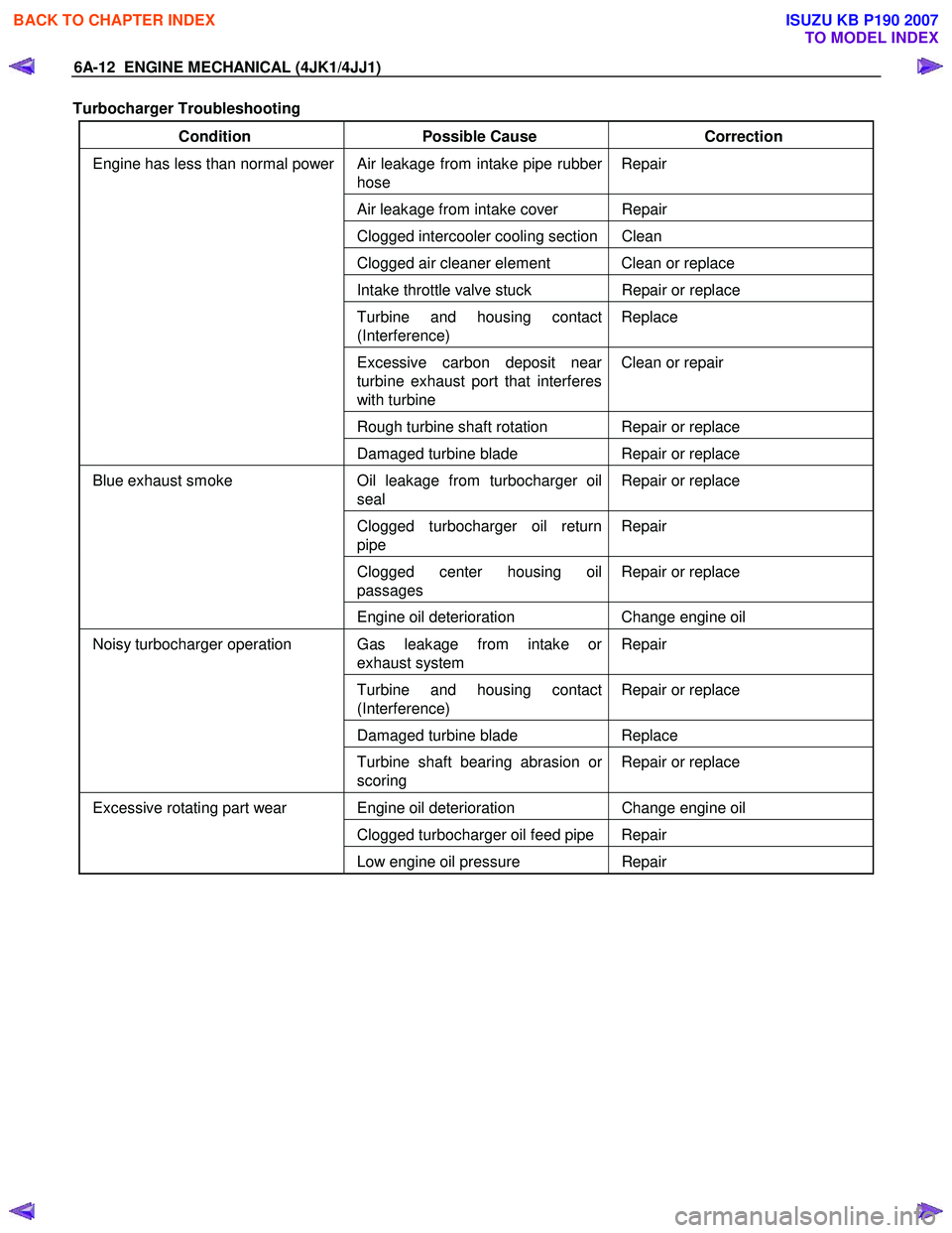
Turbocharger Troubleshooting
Condition Possible Cause Correction
Air leakage from intake pipe rubber
hose Repair
Air leakage from intake cover Repair
Clogged intercooler cooling section Clean
Clogged air cleaner element Clean or replace
Intake throttle valve stuck
Repair or replace
Turbine and housing contact
(Interference) Replace
Excessive carbon deposit near
turbine exhaust port that interferes
with turbine Clean or repair
Rough turbine shaft rotation Repair or replace
Engine has less than normal power
Damaged turbine blade Repair or replace
Oil leakage from turbocharger oil
seal Repair or replace
Clogged turbocharger oil return
pipe Repair
Clogged center housing oil
passages Repair or replace
Blue exhaust smoke
Engine oil deterioration Change engine oil
Gas leakage from intake or
exhaust system Repair
Turbine and housing contact
(Interference) Repair or replace
Damaged turbine blade
Replace
Noisy turbocharger operation
Turbine shaft bearing abrasion or
scoring Repair or replace
Engine oil deterioration
Change engine oil
Clogged turbocharger oil feed pipe Repair
Excessive rotating part wear
Low engine oil pressure Repair
BACK TO CHAPTER INDEX
TO MODEL INDEX
ISUZU KB P190 2007
Page 1373 of 6020
ENGINE MECHANICAL (4JK1/4JJ1) 6A-13
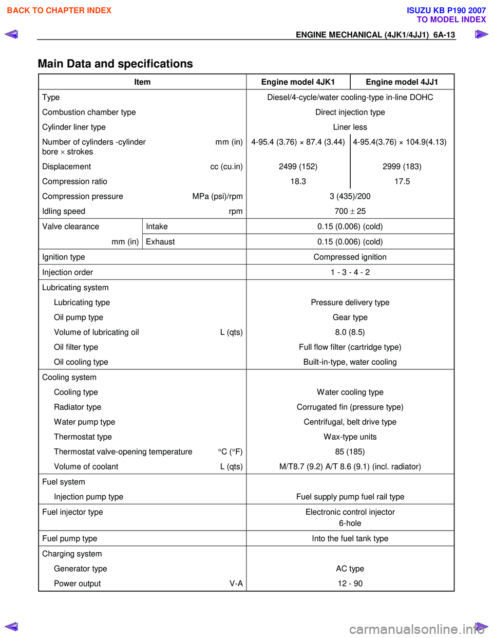
Main Data and specifications
Item Engine model 4JK1 Engine model 4JJ1
Type Diesel/4-cycle/water cooling-type in-line DOHC
Combustion chamber type Direct injection type
Cylinder liner type Liner less
Number of cylinders -cylinder
bore × strokes mm (in) 4-95.4 (3.76) × 87.4 (3.44) 4-95.4(3.76) × 104.9(4.13)
Displacement
cc (cu.in) 2499 (152) 2999 (183)
Compression ratio 18.3 17.5
Compression pressure MPa (psi)/rpm 3 (435)/200
Idling speed rpm 700 ± 25
Valve clearance Intake 0.15 (0.006) (cold)
mm (in) Exhaust 0.15 (0.006) (cold)
Ignition type Compressed ignition
Injection order 1 - 3 - 4 - 2
Lubricating system
Lubricating type Pressure delivery type
Oil pump type Gear type
Volume of lubricating oil L (qts) 8.0 (8.5)
Oil filter type Full flow filter (cartridge type)
Oil cooling type Built-in-type, water cooling
Cooling system
Cooling type W ater cooling type
Radiator type Corrugated fin (pressure type)
W ater pump type Centrifugal, belt drive type
Thermostat type W ax-type units
Thermostat valve-opening temperature °C ( °F) 85 (185)
Volume of coolant L (qts) M/T8.7 (9.2) A/T 8.6 (9.1) (incl. radiator)
Fuel system
Injection pump type Fuel supply pump fuel rail type
Fuel injector type Electronic control injector
6-hole
Fuel pump type Into the fuel tank type
Charging system
Generator type AC type
Power output V-A 12 - 90
BACK TO CHAPTER INDEX
TO MODEL INDEX
ISUZU KB P190 2007