Page 1332 of 6020

6E-298 Engine Control System (4JH1)
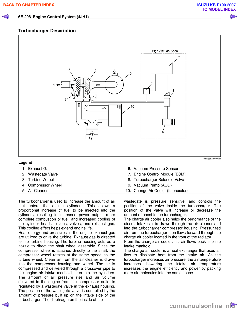
Turbocharger Description
RTW 66EMF000501
Legend
1. Exhaust Gas
2. W astegate Valve
3. Turbine W heel
4. Compressor W heel
5. Air Cleaner
6. Vacuum Pressure Sensor
7. Engine Control Module (ECM)
8. Turbocharger Solenoid Valve
9. Vacuum Pump (ACG)
10. Change Air Cooler (Intercooler)
The turbocharger is used to increase the amount of ai
r
that enters the engine cylinders. This allows a
proportional increase of fuel to be injected into the
cylinders, resulting in increased power output, more
complete combustion of fuel, and increased cooling o
f
the cylinder heads, pistons, valves, and exhaust gas.
This cooling effect helps extend engine life.
Heat energy and pressures in the engine exhaust gas
are utilized to drive the turbine. Exhaust gas is directed
to the turbine housing. The turbine housing acts as a
nozzle to direct the shaft wheel assembly. Since the
compressor wheel is attached directly to the shaft, the
compressor wheel rotates at the same speed as the
turbine wheel. Clean air from the air cleaner is drawn
into the compressor housing and wheel. The air is
compressed and delivered through a crossover pipe to
the engine air intake manifold, then into the cylinders.
The amount of air pressure rise and air volume
delivered to the engine from the compressor outlet is
regulated by a wastegate valve in the exhaust housing.
The position of the wastegate valve is controlled by the
amount of pressure built up on the intake side of the
turbocharger. The diaphragm on the inside of the
wastegate is pressure sensitive, and controls the
position of the valve inside the turbocharger. The
position of the valve will increase or decrease the
amount of boost to the turbocharger.
The charge air cooler also helps the performance of the
diesel. Intake air is drawn through the air cleaner and
into the turbocharger compressor housing. Pressurized
air from the turbocharger then flows forward through the
charge air cooler located in the front of the radiator.
From the charge air cooler, the air flows back into the
intake manifold.
The charge air cooler is a heat exchanger that uses ai
r
flow to dissipate heat from the intake air. As the
turbocharger increases air pressure, the air temperature
increases. Lowering the intake air temperature
increases the engine efficiency and power by packing
more air molecules into the same space.
BACK TO CHAPTER INDEX
TO MODEL INDEX
ISUZU KB P190 2007
Page 1333 of 6020
Engine Control System (4JH1) 6E-299
Special Tools and Equipment
Special Tools and Equipment
Illustration Tool Number/
Description
Illustration Tool Number/
Description
5-8840-2835-0 /
J-35616-A
Connector Test Adapter Kit
(W ith Test Lamp)
5-8840-0607-0 /
J-34142-B
Test Lamp
5-8840-0285-0 /
J-39200
Digital Multimeter
5-8840-0279-0 /
J-23738-A
Vacuum Pump
Tech2 Kit
Breaker Box
Adapter Harness
BACK TO CHAPTER INDEX
TO MODEL INDEX
ISUZU KB P190 2007
Page 1340 of 6020
EXHAUST SYSTEM 6F – 7
GENERAL DESCRIPTION
This system controls the formation of NOx emission by recirculating the exhaust gas into the combustion chamber
through the intake manifold.
4JA1T(L):
The two EGR valves are controlled by two Vacuum Switching Valve (VSV) controlled by EGR controller according to
signals from various sensors.
The amount of EGR depends on the number of engine rotations and the opening of the accelerator.
RTW 46ELF001201
BACK TO CHAPTER INDEX
TO MODEL INDEX
ISUZU KB P190 2007
Page 1341 of 6020
6F – 8 EXHAUST SYSTEM
4JA1TC/4JH1TC
The EGR system engine is controlled by ECM. Refer to “Engine driveability and emissions” section for detail.
RTW 46ELF001101
BACK TO CHAPTER INDEX
TO MODEL INDEX
ISUZU KB P190 2007
Page 1342 of 6020
EXHAUST SYSTEM 6F – 9
EGR SYSTEM DIAGRAM 4JA1T (L)
RTW 46AMF000301
EGR System Operation
Inspect EGR valve motion visually while changing engine RPM under no load condition after warming-up.
• Inspection point (Engine RPM)
RPM Idling 900 ∼ 960 2000 3250
Engine Front Side VSV-1
ON ON ON OFF
Engine Rear Side VSV-2 ON OFF ON OFF
ON means VSV should receive signal to move EGR valve.
OFF means VSV shouldn’t receive signal to move EGR valve.
BACK TO CHAPTER INDEX
TO MODEL INDEX
ISUZU KB P190 2007
Page 1343 of 6020
6F – 10 EXHAUST SYSTEM
4JA1TC/4JH1TC
The EGR system engine is controlled by ECM. Refer to “Engine driveability and emissions” section for detail.
RTW 46EMF000701
BACK TO CHAPTER INDEX
TO MODEL INDEX
ISUZU KB P190 2007
Page 1348 of 6020
EXHAUST SYSTEM 6F – 15
TURBOCHARGER
MAIN DATA AND SPECIFICATIONS
Engine 4JA1T(L) 4JA1TC 4JH1TC
Model IHI RHF4H IHI RHF4H IHI RHF5
Turbine type Mixed type
Compressor type Backword & rake type
Maximum permissible speed rpm 190,000 190,000 180,000
IHI : Ishikawajima Harima Heavy Industries., Ltd.
BACK TO CHAPTER INDEX
TO MODEL INDEX
ISUZU KB P190 2007
Page 1349 of 6020
6F – 16 EXHAUST SYSTEM
GENERAL DESCRIPTION
036LV002
The turbocharger internal mechanism consists of the turbine wheel, the compressor wheel, and the radial bearings.
These parts are supported by the bearing housing.
The turbocharger external mechanism consists of the compressor housing air intake port and the turbine housing
air exhaust port.
The turbocharger increases air intake efficiency. This results in increased engine power, reduced fuel consumption,
and minimal engine noise.
The turbocharger operates at very high speeds and temperatures. Part materials have been carefully selected and
machined to extremely high precision.
Turbocharger servicing requires great care and expertise.
If reduced performance is noted, check the engine for damage or wear. If there is no apparent engine damage or
wear, trouble with the turbocharger is indicated.
BACK TO CHAPTER INDEX
TO MODEL INDEX
ISUZU KB P190 2007