2007 ISUZU KB P190 engine
[x] Cancel search: enginePage 1324 of 6020
6E-290 Engine Control System (4JH1)
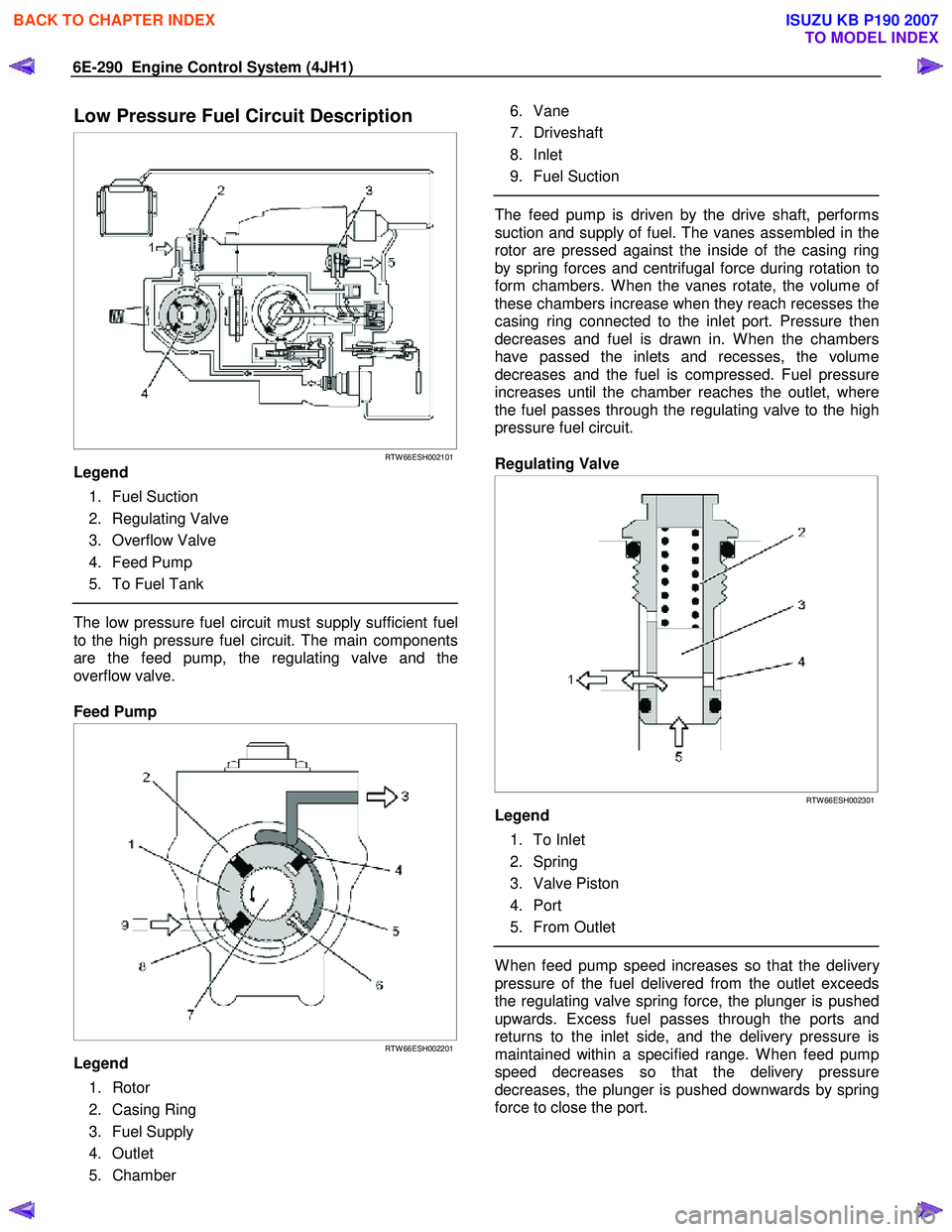
Low Pressure Fuel Circuit Description
RTW 66ESH002101
Legend
1. Fuel Suction
2. Regulating Valve
3. Overflow Valve
4. Feed Pump
5. To Fuel Tank
The low pressure fuel circuit must supply sufficient fuel
to the high pressure fuel circuit. The main components
are the feed pump, the regulating valve and the
overflow valve.
Feed Pump
RTW 66ESH002201
Legend
1. Rotor
2. Casing Ring
3. Fuel Supply
4. Outlet
5. Chamber
6. Vane
7. Driveshaft
8. Inlet
9. Fuel Suction
The feed pump is driven by the drive shaft, performs
suction and supply of fuel. The vanes assembled in the
rotor are pressed against the inside of the casing ring
by spring forces and centrifugal force during rotation to
form chambers. W hen the vanes rotate, the volume o
f
these chambers increase when they reach recesses the
casing ring connected to the inlet port. Pressure then
decreases and fuel is drawn in. W hen the chambers
have passed the inlets and recesses, the volume
decreases and the fuel is compressed. Fuel pressure
increases until the chamber reaches the outlet, where
the fuel passes through the regulating valve to the high
pressure fuel circuit.
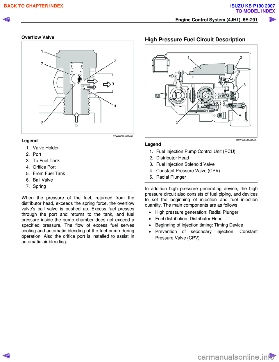
Regulating Valve
RTW 66ESH002301
Legend
1. To Inlet
2. Spring
3. Valve Piston
4. Port
5. From Outlet
W hen feed pump speed increases so that the delivery
pressure of the fuel delivered from the outlet exceeds
the regulating valve spring force, the plunger is pushed
upwards. Excess fuel passes through the ports and
returns to the inlet side, and the delivery pressure is
maintained within a specified range. W hen feed pump
speed decreases so that the delivery pressure
decreases, the plunger is pushed downwards by spring
force to close the port.
BACK TO CHAPTER INDEX
TO MODEL INDEX
ISUZU KB P190 2007
Page 1325 of 6020
Engine Control System (4JH1) 6E-291
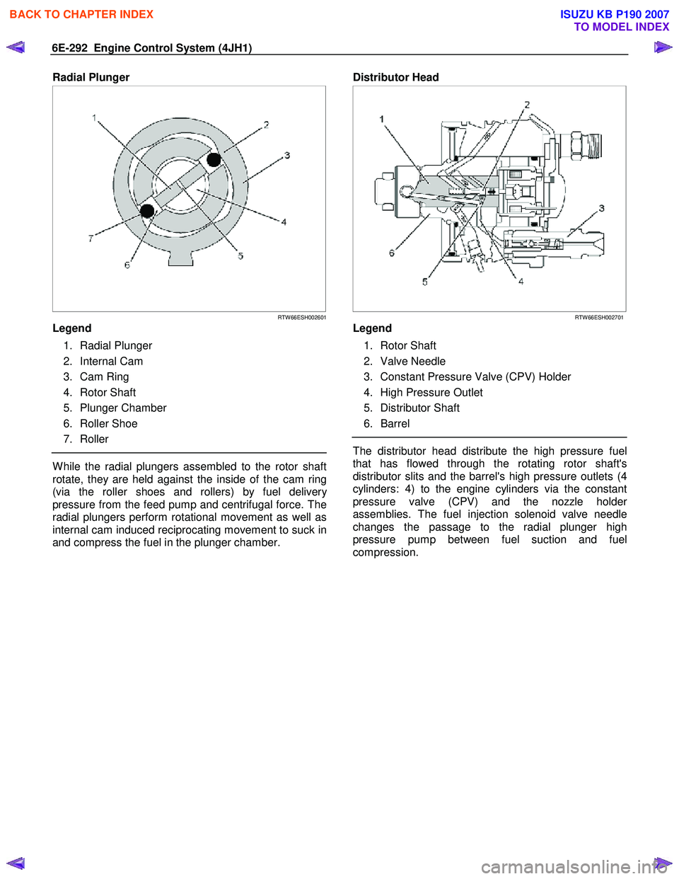
Overflow Valve
RTW 66ESH002401
Legend
1. Valve Holder
2. Port
3. To Fuel Tank
4. Orifice Port
5. From Fuel Tank
6. Ball Valve
7. Spring
W hen the pressure of the fuel, returned from the
distributor head, exceeds the spring force, the overflo
w
valve's ball valve is pushed up. Excess fuel presses
through the port and returns to the tank, and fuel
pressure inside the pump chamber does not exceed a
specified pressure. The flow of excess fuel serves
cooling and automatic bleeding of the fuel pump during
operation. Also the orifice port is installed to assist in
automatic air bleeding.
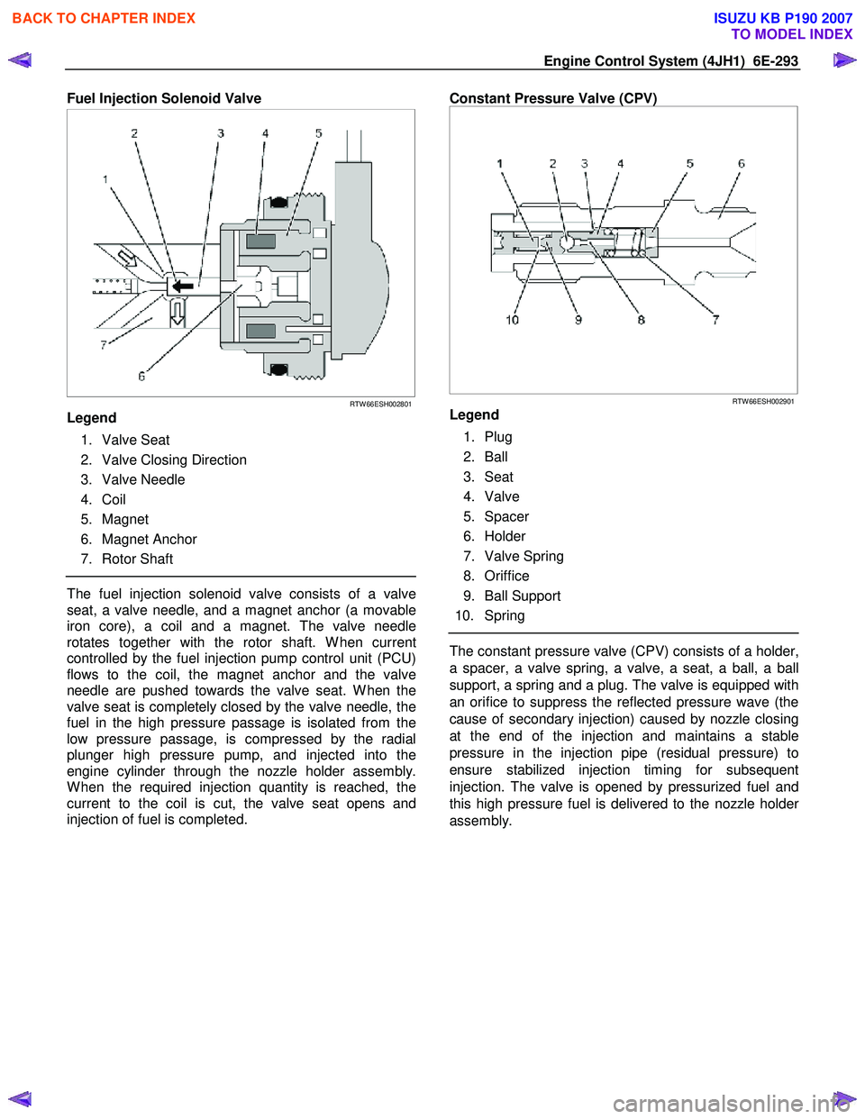
High Pressure Fuel Circuit Description
RTW 66ESH002501
Legend
1. Fuel Injection Pump Control Unit (PCU)
2. Distributor Head
3. Fuel Injection Solenoid Valve
4. Constant Pressure Valve (CPV)
5. Radial Plunger
In addition high pressure generating device, the high
pressure circuit also consists of fuel piping, and devices
to set the beginning of injection and fuel injection
quantity. The main components are as follows:
• High pressure generation: Radial Plunger
• Fuel distribution: Distributor Head
• Beginning of injection timing: Timing Device
• Prevention of secondary injection: Constant
Pressure Valve (CPV)
BACK TO CHAPTER INDEX
TO MODEL INDEX
ISUZU KB P190 2007
Page 1326 of 6020
6E-292 Engine Control System (4JH1)
Radial Plunger
RTW 66ESH002601
Legend
1. Radial Plunger
2. Internal Cam
3. Cam Ring
4. Rotor Shaft
5. Plunger Chamber
6. Roller Shoe
7. Roller
W hile the radial plungers assembled to the rotor shaft
rotate, they are held against the inside of the cam ring
(via the roller shoes and rollers) by fuel deliver
y
pressure from the feed pump and centrifugal force. The
radial plungers perform rotational movement as well as
internal cam induced reciprocating movement to suck in
and compress the fuel in the plunger chamber.
Distributor Head
RTW 66ESH002701
Legend
1. Rotor Shaft
2. Valve Needle
3. Constant Pressure Valve (CPV) Holder
4. High Pressure Outlet
5. Distributor Shaft
6. Barrel
The distributor head distribute the high pressure fuel
that has flowed through the rotating rotor shaft's
distributor slits and the barrel's high pressure outlets (4
cylinders: 4) to the engine cylinders via the constant
pressure valve (CPV) and the nozzle holde
r
assemblies. The fuel injection solenoid valve needle
changes the passage to the radial plunger high
pressure pump between fuel suction and fuel
compression.
BACK TO CHAPTER INDEX
TO MODEL INDEX
ISUZU KB P190 2007
Page 1327 of 6020
Engine Control System (4JH1) 6E-293
Fuel Injection Solenoid Valve
RTW 66ESH002801
Legend
1. Valve Seat
2. Valve Closing Direction
3. Valve Needle
4. Coil
5. Magnet
6. Magnet Anchor
7. Rotor Shaft
The fuel injection solenoid valve consists of a valve
seat, a valve needle, and a magnet anchor (a movable
iron core), a coil and a magnet. The valve needle
rotates together with the rotor shaft. W hen current
controlled by the fuel injection pump control unit (PCU)
flows to the coil, the magnet anchor and the valve
needle are pushed towards the valve seat. W hen the
valve seat is completely closed by the valve needle, the
fuel in the high pressure passage is isolated from the
low pressure passage, is compressed by the radial
plunger high pressure pump, and injected into the
engine cylinder through the nozzle holder assembly.
W hen the required injection quantity is reached, the
current to the coil is cut, the valve seat opens and
injection of fuel is completed.
Constant Pressure Valve (CPV)
RTW 66ESH002901
Legend
1. Plug
2. Ball
3. Seat
4. Valve
5. Spacer
6. Holder
7. Valve Spring
8. Oriffice
9. Ball Support
10. Spring
The constant pressure valve (CPV) consists of a holder,
a spacer, a valve spring, a valve, a seat, a ball, a ball
support, a spring and a plug. The valve is equipped with
an orifice to suppress the reflected pressure wave (the
cause of secondary injection) caused by nozzle closing
at the end of the injection and maintains a stable
pressure in the injection pipe (residual pressure) to
ensure stabilized injection timing for subsequent
injection. The valve is opened by pressurized fuel and
this high pressure fuel is delivered to the nozzle holde
r
assembly.
BACK TO CHAPTER INDEX
TO MODEL INDEX
ISUZU KB P190 2007
Page 1328 of 6020
6E-294 Engine Control System (4JH1)
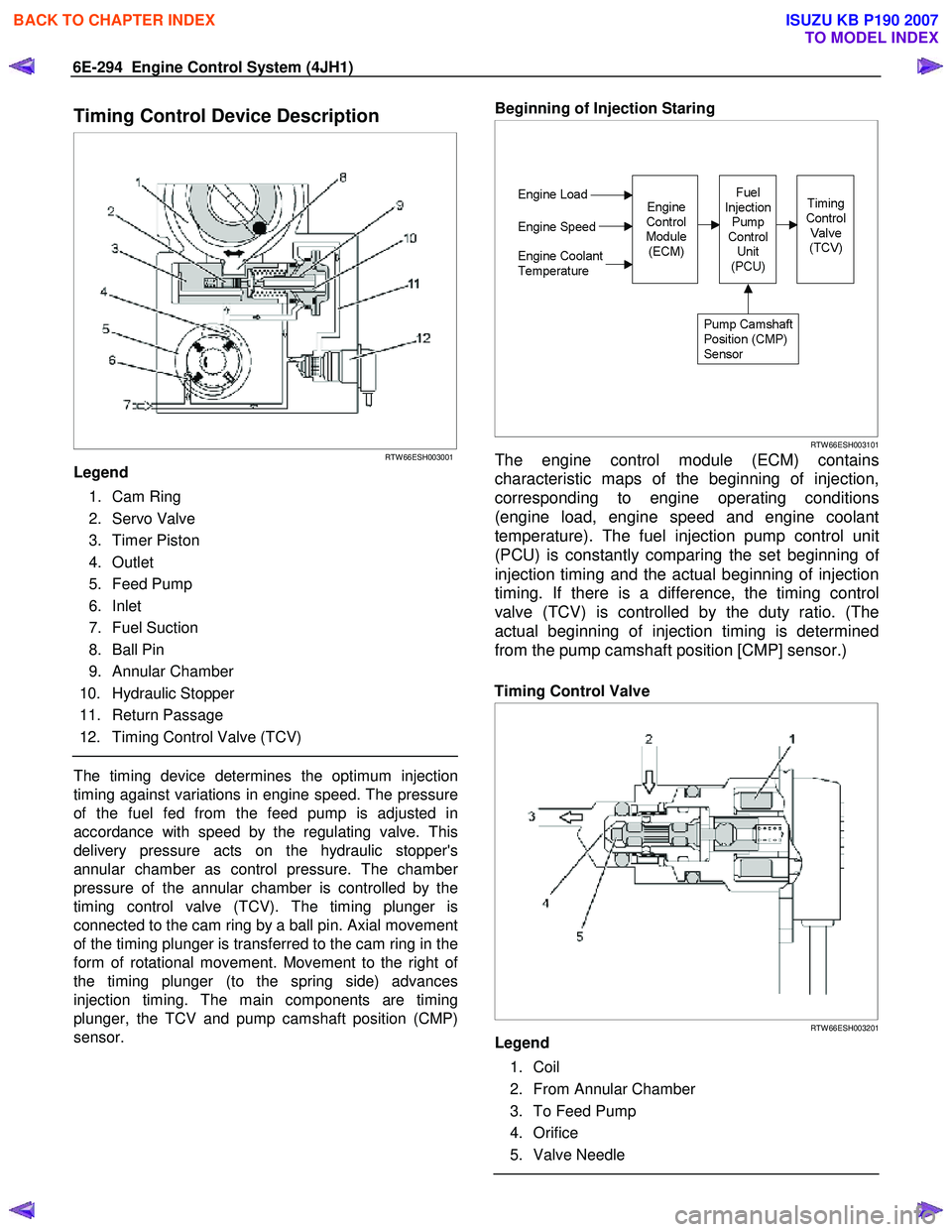
Timing Control Device Description
RTW 66ESH003001
Legend
1. Cam Ring
2. Servo Valve
3. Timer Piston
4. Outlet
5. Feed Pump
6. Inlet
7. Fuel Suction
8. Ball Pin
9. Annular Chamber
10. Hydraulic Stopper
11. Return Passage
12. Timing Control Valve (TCV)
The timing device determines the optimum injection
timing against variations in engine speed. The pressure
of the fuel fed from the feed pump is adjusted in
accordance with speed by the regulating valve. This
delivery pressure acts on the hydraulic stopper's
annular chamber as control pressure. The chambe
r
pressure of the annular chamber is controlled by the
timing control valve (TCV). The timing plunger is
connected to the cam ring by a ball pin. Axial movement
of the timing plunger is transferred to the cam ring in the
form of rotational movement. Movement to the right o
f
the timing plunger (to the spring side) advances
injection timing. The main components are timing
plunger, the TCV and pump camshaft position (CMP)
sensor.
Beginning of Injection Staring
RTW 66ESH003101
The engine control module (ECM) contains
characteristic maps of the beginning of injection,
corresponding to engine operating conditions
(engine load, engine speed and engine coolant
temperature). The fuel injection pump control unit
(PCU) is constantly comparing the set beginning o
f
injection timing and the actual beginning of injection
timing. If there is a difference, the timing control
valve (TCV) is controlled by the duty ratio. (The
actual beginning of injection timing is determined
from the pump camshaft position [CMP] sensor.)
Timing Control Valve
RTW 66ESH003201
Legend
1. Coil
2. From Annular Chamber
3. To Feed Pump
4. Orifice
5. Valve Needle
BACK TO CHAPTER INDEX
TO MODEL INDEX
ISUZU KB P190 2007
Page 1329 of 6020
Engine Control System (4JH1) 6E-295
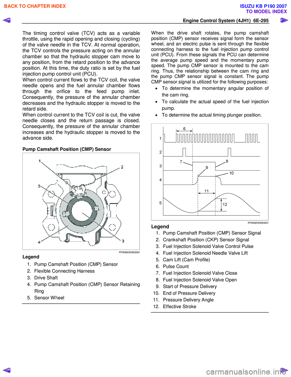
The timing control valve (TCV) acts as a variable
throttle, using the rapid opening and closing (cycling)
of the valve needle in the TCV.
At normal operation,
the TCV controls the pressure acting on the annula
r
chamber so that the hydraulic stopper cam move to
any position, from the retard position to the advance
position. At this time, the duty ratio is set by the fuel
injection pump control unit (PCU).
When control current flows to the TCV coil, the valve
needle opens and the fuel annular chamber flows
through the orifice to the feed pump inlet.
Consequently, the pressure of the annular chambe
r
decreases and the hydraulic stopper is moved to the
retard side.
When control current to the TCV coil is cut, the valve
needle closes and the return passage is closed.
Consequently, the pressure of the annular chambe
r
increases and the hydraulic stopper is moved to the
advance side.
Pump Camshaft Position (CMP) Sensor
RTW 66ESH003301
Legend
1. Pump Camshaft Position (CMP) Sensor
2. Flexible Connecting Harness
3. Drive Shaft
4. Pump Camshaft Position (CMP) Sensor Retaining Ring
5. Sensor W heel
W hen the drive shaft rotates, the pump camshaft
position (CMP) sensor receives signal form the senso
r
wheel, and an electric pulse is sent through the flexible
connecting harness to the fuel injection pump control
unit (PCU). From these signals the PCU can determine
the average pump speed and the momentary pump
speed. The pump CMP sensor is mounted to the cam
ring. Thus, the relationship between the cam ring and
the pump CMP sensor signal is constant. The pump
CMP sensor signal is utilized for the following purposes:
• To determine the momentary angular position o
f
the cam ring.
• To calculate the actual speed of the fuel injection
pump.
• To determine the actual timing plunger position.
RTW 66ESH003401Legend
1. Pump Camshaft Position (CMP) Sensor Signal
2. Crankshaft Position (CKP) Sensor Signal
3. Fuel Injection Solenoid Valve Control Pulse
4. Fuel Injection Solenoid Needle Valve Lift
5. Cam Lift (Cam Profile)
6. Pulse Count
7. Fuel Injection Solenoid Valve Close
8. Fuel Injection Solenoid Valve Open
9. Start of Pressure Delivery
10. End of Pressure Delivery
11. Pressure Delivery Angle
12. Effective Stroke
BACK TO CHAPTER INDEX
TO MODEL INDEX
ISUZU KB P190 2007
Page 1330 of 6020
6E-296 Engine Control System (4JH1)
• Momentary Cam Ring Angular Position
The momentary angular position of the cam ring is input into the fuel injection PCU as a fuel injection
solenoid valve control signal. From momentar
y
input of angular position for fluctuations in running
conditions, the fuel injection solenoid valve open
and close intervals corresponding to the cam ring's
cam lift can be accurately determined.
• Actual Injection Pump Speed
W hen the crankshaft position (CKP) sensor is faulty, the engine control module (ECM) uses the
pump CMP signal as a replacement signal.
• Actual Timing Plunger Position
The actual timing plunger position can be determined by comparing the CKP sensor signal
with the pump CMP sensor angle. This position is
used for timer control.
BACK TO CHAPTER INDEX
TO MODEL INDEX
ISUZU KB P190 2007
Page 1331 of 6020
Engine Control System (4JH1) 6E-297
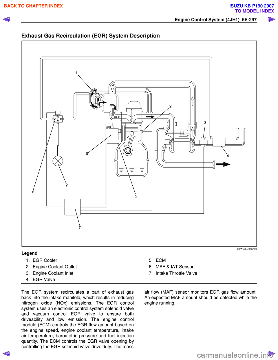
Exhaust Gas Recirculation (EGR) System Description
RTW 66ELF000101
Legend
1. EGR Cooler
2. Engine Coolant Outlet
3. Engine Coolant Inlet
4. EGR Valve
5. ECM
6. MAF & IAT Sensor
7. Intake Throttle Valve
The EGR system recirculates a part of exhaust gas
back into the intake manifold, which results in reducing
nitrogen oxide (NOx) emissions. The EGR control
system uses an electronic control system solenoid valve
and vacuum control EGR valve to ensure both
driveability and low emission. The engine control
module (ECM) controls the EGR flow amount based on
the engine speed, engine coolant temperature, intake
air temperature, barometric pressure and fuel injection
quantity. The ECM controls the EGR valve opening b
y
controlling the EGR solenoid valve drive duty. The mass
air flow (MAF) sensor monitors EGR gas flow amount.
An expected MAF amount should be detected while the
engine running.
BACK TO CHAPTER INDEX
TO MODEL INDEX
ISUZU KB P190 2007