2007 ISUZU KB P190 engine
[x] Cancel search: enginePage 1308 of 6020
6E-274 Engine Control System (4JH1)
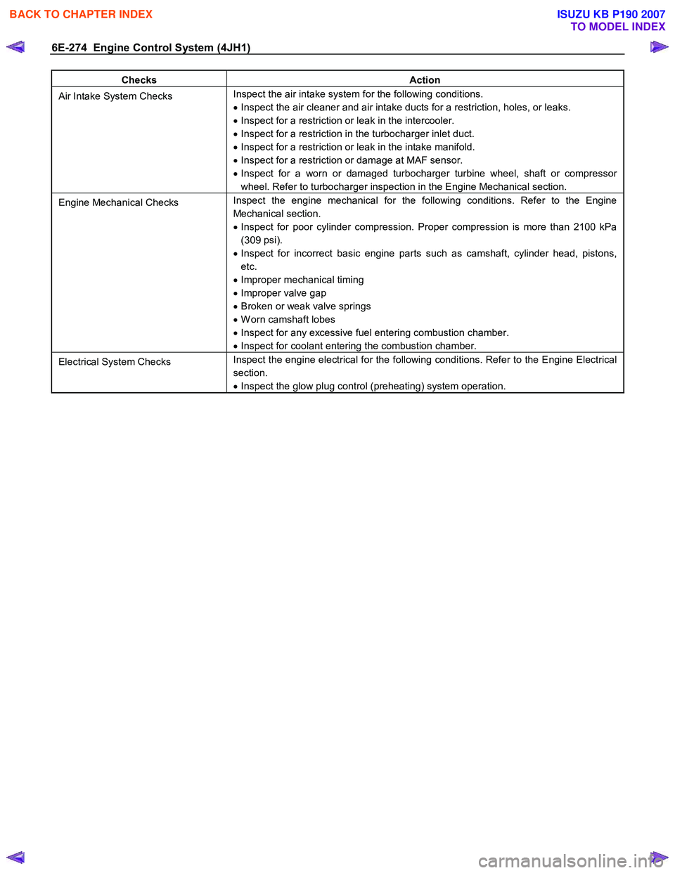
Checks Action
Air Intake System Checks Inspect the air intake system for the following conditions.
• Inspect the air cleaner and air intake ducts for a restriction, holes, or leaks.
• Inspect for a restriction or leak in the intercooler.
• Inspect for a restriction in the turbocharger inlet duct.
• Inspect for a restriction or leak in the intake manifold.
• Inspect for a restriction or damage at MAF sensor.
• Inspect for a worn or damaged turbocharger turbine wheel, shaft or compressor
wheel. Refer to turbocharger inspection in the Engine Mechanical section.
Engine Mechanical Checks Inspect the engine mechanical for the following conditions. Refer to the Engine
Mechanical section.
• Inspect for poor cylinder compression. Proper compression is more than 2100 kPa
(309 psi).
• Inspect for incorrect basic engine parts such as camshaft, cylinder head, pistons,
etc.
• Improper mechanical timing
• Improper valve gap
• Broken or weak valve springs
• W orn camshaft lobes
• Inspect for any excessive fuel entering combustion chamber.
• Inspect for coolant entering the combustion chamber.
Electrical System Checks Inspect the engine electrical for the following conditions. Refer to the Engine Electrical
section.
• Inspect the glow plug control (preheating) system operation.
BACK TO CHAPTER INDEX
TO MODEL INDEX
ISUZU KB P190 2007
Page 1309 of 6020
Engine Control System (4JH1) 6E-275
Repair Instructions
Engine Control Module (ECM) Replacement
Engine Control Module (ECM) Replacement
Procedure
Important:
If the ECM is to be replaced the following programmed
contents MUST be reprogrammed into the new ECM. • Vehicle identification number (VIN).
• Latest software/calibrations if released. Refer to
Service Programming System (SPS) Description
and Service Programming System (SPS) (Remote
Procedure) or Service Programming System (SPS)
(Pass-Thru Procedure) in this section
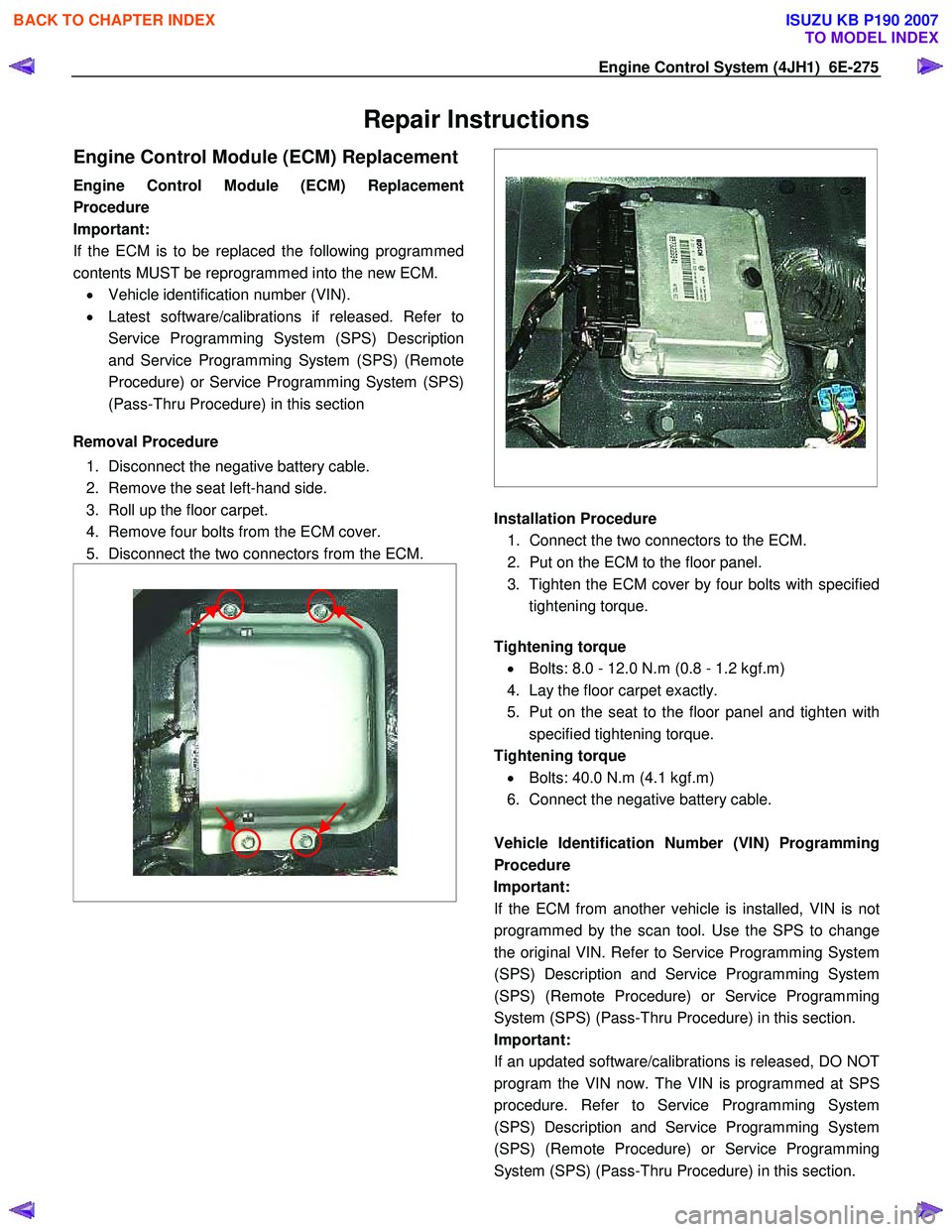
Removal Procedure
1. Disconnect the negative battery cable.
2. Remove the seat left-hand side.
3. Roll up the floor carpet.
4. Remove four bolts from the ECM cover.
5. Disconnect the two connectors from the ECM.
Installation Procedure
1. Connect the two connectors to the ECM.
2. Put on the ECM to the floor panel.
3. Tighten the ECM cover by four bolts with specified tightening torque.
Tightening torque
• Bolts: 8.0 - 12.0 N.m (0.8 - 1.2 kgf.m)
4. Lay the floor carpet exactly.
5. Put on the seat to the floor panel and tighten with specified tightening torque.
Tightening torque • Bolts: 40.0 N.m (4.1 kgf.m)
6. Connect the negative battery cable.
Vehicle Identification Number (VIN) Programming
Procedure
Important: If the ECM from another vehicle is installed, VIN is no
t
programmed by the scan tool. Use the SPS to change
the original VIN. Refer to Service Programming System
(SPS) Description and Service Programming System
(SPS) (Remote Procedure) or Service Programming
System (SPS) (Pass-Thru Procedure) in this section.
Important:
If an updated software/calibrations is released, DO NOT
program the VIN now. The VIN is programmed at SPS
procedure. Refer to Service Programming System
(SPS) Description and Service Programming System
(SPS) (Remote Procedure) or Service Programming
System (SPS) (Pass-Thru Procedure) in this section.
BACK TO CHAPTER INDEX
TO MODEL INDEX
ISUZU KB P190 2007
Page 1310 of 6020
6E-276 Engine Control System (4JH1)
1. Connect the scan tool to the vehicle DLC, with theengine and the scan tool OFF.
2. Turn ON the scan tool.
3. Select Diagnostic > appropriate vehicle identification > Powertrain > 4JH1-TC >
Programming > Program VIN.
4. Input correct VIN reading from stamped VIN o
r
affixed VIN plate on the vehicle.
Select Lock ECU and lock the programmed VIN.
Service Programming System (SPS)
Description
The service programming system (SPS) allows a
technician to program a control module through the data
link connector (DLC). The information transfer circuit that
is used at the DLC is the same serial data circuit used be
the scan tool for retrieving diagnostic trouble codes
(DTCs), displaying data, clearing DTCs etc. This
procedure offers the ability to install software/calibrations
matched to a particular vehicle.
Most control modules have two types of memory. The
software/calibrations reside in the flash memory. The two
types of memory are listed below: • Electrically Erasable Programmable Read Onl
y
Memory (EEPROM).
This type of memory allows selected portions o
f
memory to be programmed while other portions
remain unchanged.
Certain learned values reside in the EEPROM, such as:
- The vehicle identification number (VIN)
- The software/calibrations identification numbers
- The control module security information
• Flash Read Only Memory-Flash Memory
Flash memory has increased memory storage capacity. During programming, all information within
this type of memory is erased, and then replaced
with entirely new information.
Service Programming Methods
The two methods of programming an engine control
module (ECM) are listed below: • Remote Programming
• Pass Thru Programming
For information on programming an ECM using one o
f
the methods listed above, refer to Service Programming
System (SPS) (Remote Procedure) or Service
Programming System (SPS) (Pass-Thru Procedure).
Before Programming a Control Module
Important:
DO NOT program an existing ECM with the identical
software/calibration package. This procedure is not a
short cut to correct the driveability condition. This is an
ineffective repair. An ECM should only be programmed
when the following occurs: • W hen a service procedure instructs you to replace
the ECM. W hen the ECM from another vehicle is
installed, VIN must be changed. And change
vehicle information as necessary such as type o
f
transmission.
• An updated software/calibrations is released.
Ensure that the following conditions are met before
programming an ECM: • The scan tool PCMCIA card is programmed with
the latest software.
• The TIS 2000 is installed with the latest software.
• The hardware key is plugged into the compute
r
port.
• Vehicle system voltage:
- There are no charging system concerns. All charging system concerns must be repaired
before programming the ECM.
- The battery voltage is greater than 12 volts bu
t
less than 16 volts. The battery must be fully
charged before programming the ECM.
-
A battery charger is NOT connected to the
vehicles battery. Incorrect system voltage o
r
voltage fluctuations from a battery charger may
cause programming failure or ECM damage.
- Turn OFF or disable any system that may put a load on the vehicles battery. Turn OFF o
r
disable systems such as:
◊ Heating, ventilation, and air conditioning
(HVAC) systems
◊ Headlights
◊ Room lights
◊ Accessory equipment
• The ignition switch is in the proper position. The
scan tool prompts you to turn ON the ignition, with
the engine OFF. DO NOT change the position o
f
the ignition switch during the programming
procedure unless instructed to do so.
• All tool connections are secure:
- The RS-232 cable
- The connection at the DLC
- The voltage supply circuits
BACK TO CHAPTER INDEX
TO MODEL INDEX
ISUZU KB P190 2007
Page 1311 of 6020
Engine Control System (4JH1) 6E-277
• DO NOT disturb the tool harnesses while
programming. If an interruption occurs during the
programming procedure, programming failure o
r
ECM damage may occur.
• If you are performing the Pass-Thru programming
procedure using a notebook computer without the
power cord, ensure that the internal battery is full
y
charged.
Service Programming System (SPS)
(Remote Procedure)
The Remote Service Programming System (SPS)
method is a three-step process that involves the
following procedures: 1. Connecting the scan tool to the vehicle and obtaining the information from the engine control
module (ECM).
2. Connecting the scan tool to the terminal and downloading a new calibration file from the terminal
into the scan tool memory.
3. Reconnecting the scan tool to the vehicle and uploading the new calibration file into the ECM.
Performing the Remote Procedure 1. Connect the scan tool to the vehicle and obtain the ECM information using the following procedure:
Important:
Ensure the ECM is installed in the vehicle and the batter
y
is fully charged before programming. a. Connect the scan tool to the vehicle data linkconnector (DLC), with the engine and the scan
tool OFF.
b. Turn ON the scan tool.
c. Press Enter at the title screen.
d. Turn ON the ignition, with the engine OFF.
e. Select Service Programming System at the Main Menu.
f. Select Request Info.
g. If there is already stored in the scan tool, the existing data is displayed on the screen. The
scan tool asks user to keep existing data Keep
Data or Continue to request new vehicle
information from the ECM. If there is no data in
the scan tool, it will immediately start vehicle
identification.
h. Enter the vehicle description by following the on- screen instructions based on stamped VIN o
r
affixed VIN plate on the vehicle.
i. During obtaining information, the scan tool is
receiving information from any modules at the
same time. But only ECM information is
displayed on the screen.
j. Turn OFF all accessories and select Continue.
k. Verify that the correct VIN is entered on the scan tool. If the VIN is incorrect, write down the
correct VIN.
2. Turn OFF the scan tool.
3. Disconnect the scan tool from the vehicle.
4. Turn OFF the ignition.
5. Transfer the data from the terminal to the scan tool using the following procedure:
Important:
The TIS supports service programming with the scan
tool scan tool only. a. Connect the scan tool to the terminal.
b. Launch the TIS application at the terminal.
c. Select the Service Programming System at the main screen.
d. Highlight the following information on the Selec
t
Diagnostic Tool and Programming Process
screen: • Select Diagnostic Tool-Select scan tool.
• Select Programming Process-Identif
y
whether an existing ECM is being
reprogrammed or an ECM is being
replaced with a new one.
• Select ECU Location-Select Vehicle.
e. Select Next.
f. Verify the connections on the Preparing fo
r
Communication screen and select Next.
g. Verify the VIN on the Validate Vehicle Identification Number (VIN) screen and selec
t
Next.
Important:
If the ECM is replaced to new one, VIN does no
t
displayed. Input correct VIN reading from stamped VIN
or affixed VIN plate on the vehicle. If the ECM from
another vehicle is installed, input correct VIN by same
way.
h. Highlight Engine on the System Type screen and select Next, if requested.
i. Complete the following information based on the service ID plate on the Validate Vehicle
Data screen until Next is highlighted: • Model
• Model Year
• Engine
• Type of Transmission
BACK TO CHAPTER INDEX
TO MODEL INDEX
ISUZU KB P190 2007
Page 1312 of 6020
6E-278 Engine Control System (4JH1)
• Destination Code
j. Select Next.
k. Verify your selection on the Summary screen.
Important:
Refer to Service Bulletins before service programming is
performed if the bulletins are listed along with the
calibration files.
Important:
Select Cancel if you receive a message stating that the
calibration selected is already the current calibration in
the ECM and reprogramming with the same download is
not allowed.
l. Select Reprog.
m. The Transfer Data screen will appear until the progress bar reaches 100%.
6. Close the application and return to the TIS application selection screen after the download is
complete.
7. Turn OFF the scan tool.
8. Disconnect the scan tool from the terminal.
9. Transfer the data from the scan tool to the ECM using the following procedure:
a. Connect the scan tool to the vehicle DLC, with the engine and the scan tool OFF.
b. Turn ON the scan tool.
c. Press Enter at the Title screen.
d. Turn ON the ignition, with the engine OFF.
e. Select Service Programming System.
f. Select the Program ECU on the scan tool.
g. Follow the on-screen instructions and select Continue.
h. Programming in Process will appear until the progress bar reaches 100%.
Important:
The vehicle fitted with automatic transmission, Check
Trans lamp may blink while programming the ECM since
communication between the ECM and TCM is
interrupted. Clear DTC in any module afte
r
programming.
i. Select Continue and exit the program after the scan tool displays Programming W as
Successful.
10. Turn OFF the ignition.
11. Turn OFF the scan tool.
12. Disconnect the scan tool from the vehicle.
Service Programming System (SPS) (Pass-
Thru Procedure)
Pass-Thru programming allows the scan tool to remain
connected to the terminal and to the vehicle throughou
t
the programming process. The vehicle must be in close
proximity to the terminal while using Pass-Thru.
Important:
The TIS supports service programming with the scan
tool scan tool only.
1. Launch the TIS application at the terminal.
2. Select the Service Programming System at the main screen.
3. Highlight the following information on the Selec
t
Diagnostic Tool and Programming Process screen:
• Select Diagnostic Tool-Select Pass-Thru
• Select Programming Process-Identify whethe
r
as existing engine control module (ECM) is
being reprogrammed or an ECM is being
replaced with a new one.
• Select ECU Location-Select Vehicle.
4. Select Next.
5. Complete all vehicle data on the Preparing fo
r
Communication/Determine Vehicle screen until
Next is highlighted.
6. Select Next.
7. Follow the instruction on the Preparing fo
r
Communication screen.
Important:
In order to reduce the potential for signal loss, the RS-
232 cable should not be more than 25 feet long.
8. Select Next.
9. Verify the VIN on the Validate Vehicle Identification Number (VIN) screen and select Next.
Important:
If the ECM is replaced to new one, VIN does no
t
displayed. Input correct VIN reading from stamped VIN
or affixed VIN plate on the vehicle. If the ECM from
another vehicle is installed, input correct VIN by same
way. 10. Highlight Engine on the System Type screen and
select Next, if requested.
11. Complete the following information based on the service ID plate on the Validate Vehicle Data
screen until Next is highlighted:
• Model
• Model Year
• Engine
• Type of Transmission
• Destination Code
12. Select Next.
13. Verify your selection on the Summary screen.
BACK TO CHAPTER INDEX
TO MODEL INDEX
ISUZU KB P190 2007
Page 1313 of 6020
Engine Control System (4JH1) 6E-279
Important:
Refer to Service Bulletins before service programming is
performed if the bulletins are listed along with the
calibration files.
Important:
Select Cancel if you receive a message stating that the
calibration selected is already the current calibration in
the scan tool and reprogramming with the same
download is not allowed.
14. Select Reprog.
15. The Transfer Data screen will appear until the progress bar reaches 100%.
Important:
The vehicle fitted with automatic transmission, Check
Trans lamp may blink while programming the ECM since
communication between the ECM and TCM is
interrupted. Clear DTC in any module afte
r
programming. 16. Select Close on the Programming Complete
screen.
17. Turn OFF the scan tool.
18. Disconnect the scan tool from the vehicle.
Accelerator Pedal Position (APP) Sensor
Replacement
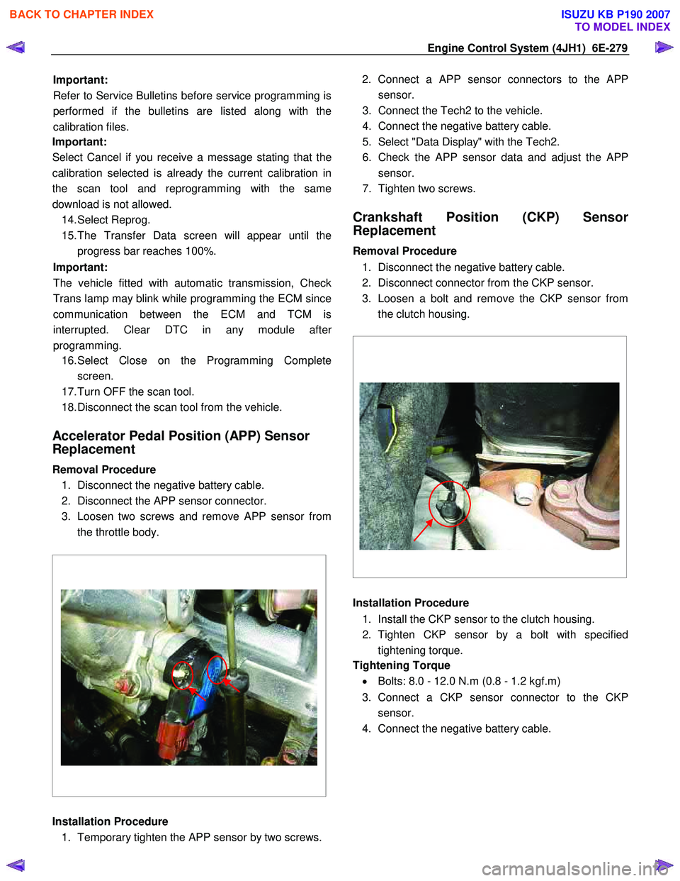
Removal Procedure 1. Disconnect the negative battery cable.
2. Disconnect the APP sensor connector.
3. Loosen two screws and remove APP sensor from the throttle body.
Installation Procedure 1. Temporary tighten the APP sensor by two screws. 2. Connect a APP sensor connectors to the
APP
sensor.
3. Connect the Tech2 to the vehicle.
4. Connect the negative battery cable.
5. Select "Data Display" with the Tech2.
6. Check the APP sensor data and adjust the
APP
sensor.
7. Tighten two screws.
Crankshaft Position (CKP) Sensor
Replacement
Removal Procedure
1. Disconnect the negative battery cable.
2. Disconnect connector from the CKP sensor.
3. Loosen a bolt and remove the CKP sensor from the clutch housing.
Installation Procedure
1. Install the CKP sensor to the clutch housing.
2. Tighten CKP sensor by a bolt with specified tightening torque.
Tightening Torque
• Bolts: 8.0 - 12.0 N.m (0.8 - 1.2 kgf.m)
3. Connect a CKP sensor connector to the CKP sensor.
4. Connect the negative battery cable.
BACK TO CHAPTER INDEX
TO MODEL INDEX
ISUZU KB P190 2007
Page 1314 of 6020
6E-280 Engine Control System (4JH1)
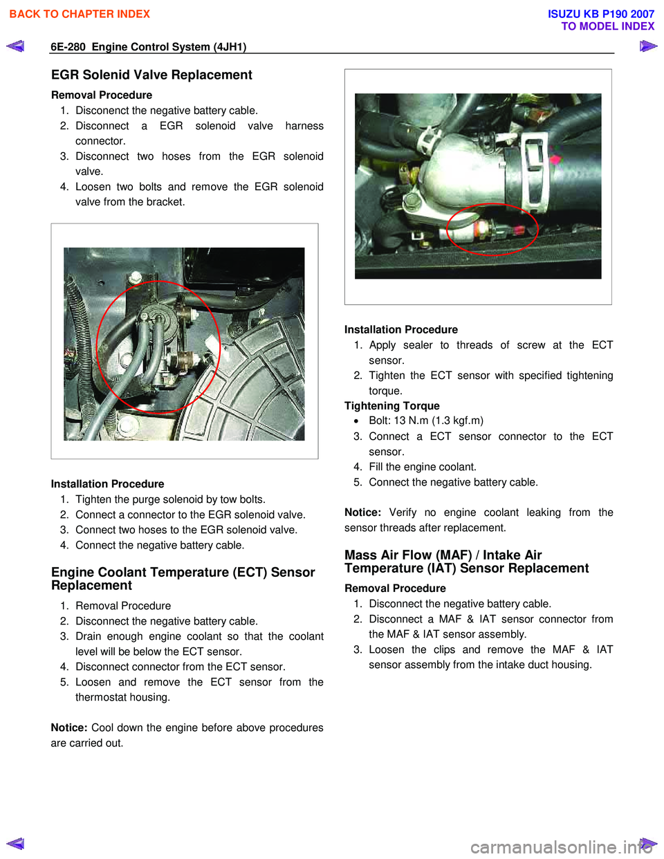
EGR Solenid Valve Replacement
Removal Procedure 1. Disconenct the negative battery cable.
2. Disconnect a EGR solenoid valve harness connector.
3. Disconnect two hoses from the EGR solenoid valve.
4. Loosen two bolts and remove the EGR solenoid valve from the bracket.
Installation Procedure
1. Tighten the purge solenoid by tow bolts.
2. Connect a connector to the EGR solenoid valve.
3. Connect two hoses to the EGR solenoid valve.
4. Connect the negative battery cable.
Engine Coolant Temperature (ECT) Sensor
Replacement
1. Removal Procedure
2. Disconnect the negative battery cable.
3. Drain enough engine coolant so that the coolant level will be below the ECT sensor.
4. Disconnect connector from the ECT sensor.
5. Loosen and remove the ECT sensor from the thermostat housing.
Notice: Cool down the engine before above procedures
are carried out.
Installation Procedure
1.
Apply sealer to threads of screw at the ECT
sensor.
2. Tighten the ECT sensor with specified tightening torque.
Tightening Torque • Bolt: 13 N.m (1.3 kgf.m)
3. Connect a ECT sensor connector to the ECT sensor.
4. Fill the engine coolant.
5. Connect the negative battery cable.
Notice: Verify no engine coolant leaking from the
sensor threads after replacement.
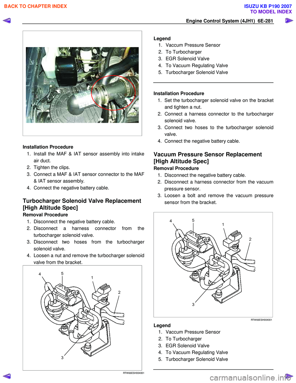
Mass Air Flow (MAF) / Intake Air
Temperature (IAT) Sensor Replacement
Removal Procedure
1. Disconnect the negative battery cable.
2. Disconnect a MAF & IAT sensor connector from the MAF & IAT sensor assembly.
3. Loosen the clips and remove the MAF & IAT sensor assembly from the intake duct housing.
BACK TO CHAPTER INDEX
TO MODEL INDEX
ISUZU KB P190 2007
Page 1315 of 6020
Engine Control System (4JH1) 6E-281
Installation Procedure
1. Install the MAF & IAT sensor assembly into intake air duct.
2. Tighten the clips.
3. Connect a MAF & IAT sensor connector to the MAF & IAT sensor assembly.
4. Connect the negative battery cable.
Turbocharger Solenoid Valve Replacement
[High Altitude Spec]
Removal Procedure
1. Disconnect the negative battery cable.
2. Disconnect a harness connector from the turbocharger solenoid valve.
3. Disconnect two hoses from the turbocharge
r
solenoid valve.
4. Loosen a nut and remove the turbocharger solenoid valve from the bracket.
RTW 66ESH004001
Legend
1. Vaccum Pressure Sensor
2. To Turbocharger
3. EGR Solenoid Valve
4. To Vacuum Regulating Valve
5. Turbocharger Solenoid Valve
Installation Procedure
1. Set the turbocharger solenoid valve on the bracke
t
and tighten a nut.
2. Connect a harness connector to the turbocharge
r
solenoid valve.
3. Connect two hoses to the turbocharger solenoid valve.
4. Connect the negative battery cable.
Vacuum Pressure Sensor Replacement
[High Altitude Spec]
Removal Procedure
1. Disconnect the negative battery cable.
2. Disconnect a harness connector from the vacuum pressure sensor.
3. Loosen a bolt and remove the vacuum pressure sensor from the bracket.
RTW 66ESH004001
Legend
1. Vaccum Pressure Sensor
2. To Turbocharger
3. EGR Solenoid Valve
4. To Vacuum Regulating Valve
5. Turbocharger Solenoid Valve
BACK TO CHAPTER INDEX
TO MODEL INDEX
ISUZU KB P190 2007