2007 ISUZU KB P190 reset
[x] Cancel search: resetPage 3503 of 6020
Engine Management – V6 – Diagnostics Page 6C1-2–225
F5: EVAP Purge Solenoid
F6: Engine Speed Control
F7: Starter Relay Test
F8: Fuel Injector Balance
F5: Additional Functions
W hen this selection is made from the Tech 2 screen, an additional two choices are provided:
F0: System Identification: In this mode, Tech 2 will display the engine identification screen.
F1: Security Information: W hen selected, this mode displays various engine management data parameters relating to the security system.
F6: Programming
W ithin this selection, there are five programming selections available:
F0: Immobiliser Link to ECM/PIM
F1: Reset ECU
F2: Fuel Trim Reset
F3: Reset Engine Oil Life
F4: Throttle Body Relearn
BACK TO CHAPTER INDEX
TO MODEL INDEX
ISUZU KB P190 2007
Page 3518 of 6020

Engine Management – V6 – Diagnostics Page 6C1-2–240
Cruise Control Switch: This parameter displays the state of the cruise control on/off switch input to the control module.
Cruise Control Disengagement Reason: The parameter displays which of a possible 28 causes for the cruise control
to disengage.
CC Disengagement 1 – 8 History (Cruise Control): The parameter displays the last 8 cruise control disengages in
order from 1 to 8, with 8 being the most recent. There are about 28 possible causes for the cruise control to disengage.
Cruise Resume/Acceleration Switch: This parameter displays the state of the cruise control resume/accel switch
position input to the ECM.
Cruise Set / Coast Switch: This parameter displays the state of the cruise controls set/decel. switch position input to
the ECM.
Cycles of Misfire: This parameter displays the number of misfire tests during 200 engine revolutions.
Cylinder 1 – 6 Injector Circuit Status: This parameter displays the state of the fuel injector control circuit. The
parameter displays ‘Fault’ if the fuel injector control circuit is open, shorted to ground, or shorted to voltage. This
parameter displays ‘Undefined Status’ until the control circuit has been commanded ‘On’.
Dec. Fuel Cutoff (Deceleration): This parameter displays the status of the ECM operating mode, used to turn off the
fuel injectors and the evaporative emission (EVAP) canister purge valve during certain deceleration conditions.
Desired Engine Idle Speed: This parameter displays the desired engine idle speed as commanded by the ECM.
Desired Throttle Position: This parameter displays the desired throttle position (TP) angle commanded by the ECM.
Distance Since DTC Cleared: This parameter displays the distance (km) travelled since any diagnostic trouble code
(DTC) has been cleared from the ECM memory.
DTC Set This Ignition: This parameter displays Yes if a DTC set on the current ignition cycle.
ECM Immobilized: This parameter displays ‘Yes’ when an internal control module reset occurs. Tech 2 will display ‘No’
under normal operating conditions.
Electronic Throttle Control Learn Counter: W hen the ECM performs a throttle body relearn procedure, the throttle
plate is commanded to move from the rest position (7% open) to full closed (0%), then to around 10% open.
At the start of this procedure, the Tech 2 ‘TAC Learn Counter’ parameter should display 0, then count up to 11 after the
procedure is completed. If the counter did not start at 0 or if the counter did not end at 11, a fault has occurred and a
DTC should set.
Engine Control Ignition Relay: This parameter displays the state of the control circuit for control module power relay
as commanded by the ECM.
Engine Control Ignition Relay Feedback: This parameter displays the voltage available at the engine control ignition
relay pin of the control module.
Engine Load: This parameter displays the calculated engine load in percent based on inputs to the control module from
various engine sensors.
Engine Oil Life Remaining: This parameter displays the percentage of engine oil life remaining. The controller
calculates the engine oil life by monitoring engine load, collant temperature and engine speed.
Engine Oil Pressure: This parameter displays the oil pressure in kPa from the ECM, developed from the engine oil
pressure (EOP) sensor input.
Engine Oil Pressure Sensor: This parameter displays ‘High’ if the engine oil pressure is within the correct range. If the
ECM detects that the engine oil pressure is not within the correct range, Tech 2 will display ‘Low’.
Engine Runtime: This parameter displays the time elapsed since the engine was started.
Engine Speed: This parameter displays the speed of the engine crankshaft rotation from information received from the
CKP sensor. If there is a CKP sensor DTC, the ECM calculates the engine speed from one of the camshaft position
(CMP) sensors.
EVAP Purge Solenoid (Evaporative Emission): This parameter displays the on-time or duty cycle of the EVAP
canister purge solenoid commanded by the ECM. Zero percent indicates no purge. One hundred percent indicates full
purge.
EVAP Purge Solenoid Valve Circuit Status (Evaporative Emission): This parameter displays the state of the EVAP
purge solenoid control circuit. The parameter displays ‘Fault’ if the EVAP purge solenoid control circuit is open, shorted
to ground, or shorted to voltage. The parameter displays ‘Undefined Status’ until the circuit has been established as
‘OK’.
Cooling Fan Relay: This parameter displays the control module commanded state of the fan relay control circuit.
BACK TO CHAPTER INDEX
TO MODEL INDEX
ISUZU KB P190 2007
Page 3519 of 6020
Engine Management – V6 – Diagnostics Page 6C1-2–241
Cooling Fan Relay Circuit Status: This parameter displays the state of the fan relay control circuit. The parameter
displays ‘Fault’ if the fan relay control circuit is open, shorted to ground, or shorted to voltage. The parameter displays
‘Undefined’ until the relay control circuit has been determined as being ‘OK’.
Fuel Level: This parameter displays the amount of fuel in the fuel tank in litres, as calculated by the ECM from data
received from the fuel level sensor.
Fuel Level Sensor: This parameter displays the voltage received from the fuel level sensor in the fuel tank, by the ECM.
Fuel Pump Relay Circuit Status: This parameter displays the state of the fuel pump relay control circuit. The
parameter displays ‘Fault’ if the fuel pump relay control circuit is open, shorted to ground, or shorted to voltage. The
parameter displays ‘Undefined’ until the relay control circuit has been determined as being ‘OK’.
Fuel Pump Relay: This parameter displays the ECM commanded state of the fuel pump relay control circuit.
Fuel Trim Learn: This parameter displays ‘Enabled’ when conditions are appropriate for enabling long term fuel trim
corrections. This indicates that the long term fuel trim is adapting continuing amounts of short term fuel trim. If Tech 2
displays ‘Disabled’, then long term fuel trim will not respond to changes in short term fuel trim.
Ignition Accessory Signal: This parameter displays ‘On’ when the control module detects a voltage at the
ignition ‘ACC’ terminal, X1-4 of the ignition switch.
Ignition On Signal: This parameter displays ‘On’ when the control module detects a voltage at the ignition ‘IGN’
terminal X1-3 of the ignition switch.
Initial Brake Apply Signal: This parameter displays the status of the brake lamp switch. Before the cruise control can
be activated, this switch contact must be open circuit when the brake pedal is pressed.
Injection Time Cylinder 1 – 6: This parameter displays the amount of fuel injector On-time or pulse width as
commanded by the ECM.
Intake Air Temperature: This parameter displays the temperature of the air entering the air induction system based on
input to the ECM from the intake air temperature (IAT) sensor.
Knock Sensor Signal (Bank 1 or Bank 2): This parameters displays the voltage input to the control module from the
knock sensor (KS).
Knock Retard: This parameter indicates the amount of spark advance in crankshaft degrees, that the ECM removes
from the ignition control (IC) spark advance in response to the signal from the knock sensors.
Knock Retard Cylinder 1 – 6: This parameter displays the knock retard as commanded by the ECM for cylinders 1-6.
Each cylinder is controlled individually based on both knock sensor signal inputs.
Loop Status B1S1 / B2S1 (Bank 1 or Bank 2 Sensor 1): This parameter displays the state of the fuel control system
as commanded by the ECM. ‘Closed’ Loop operation indicates that the ECM is controlling the fuel delivery based on the
oxygen sensors input signal. In ‘Open’ Loop operation the ECM ignores the oxygen sensor input signal and bases the
amount of fuel to be delivered on other sensor inputs.
LTFT Idle/Deceleration (Bank 1 or Bank 2) (Long Term Fuel Trim): This parameter displays the commanded Long
Term Fuel Trim correction by the ECM for bank 1 or bank 2 for idle and deceleration conditions.
LTFT Cruise/Acceleration (Bank 1 or Bank 2) (Long Term Fuel Trim): This parameter displays the commanded Long
Term Fuel Trim correction by the ECM for bank 1 or bank 2 for cruise and acceleration conditions.
Malfunction Indicator (MI): This parameter displays the commanded (‘On, ‘Off’ or ‘Flashing’) state of the malfunction
indicator lamp (MIL) control circuit by the ECM.
Malfunction Indicator (MI) Circuit Status: This parameter displays the state of the MIL control circuit. The parameter
displays ‘Fault’ if the MIL control circuit is open, shorted to ground, or shorted to voltage. This parameter displays
‘Undefined Status’ until the circuit has been determined as being ‘OK’.
Mass Air Flow: This parameter displays the measured quantity (g/s) of air flowing into the engine during all operating
conditions.
Mass Air Flow Sensor: This parameter displays the signal voltage from the mass air flow (MAF) sensor to the ECM.
Misfire Current Cyl. #1 – #6: Tech 2 displays a range of 0 – 200 counts. This parameter displays the number of
misfires that have been detected during the last 200 cylinder firing events. The counters may normally display some
activity, but the activity should be nearly equal for all of the cylinders, and in low numbers.
Misfire History Cyl. #1 – #6: Tech 2 displays a range of 0 – 65,535 counts. The misfire history counters display the total
level of misfire that has been detected on each cylinder. The misfire history counters will not update or show any activity
until a misfire DTC P0300 has become active. The misfire history counters will update every 200 cylinder firing events.
Oil Level: W hen the ECM receives information from the engine oil level switch, where the engine oil level is within
preset parameters, Tech 2 will display ‘Normal’. If not within preset parameters, the display will show ‘Low’.
BACK TO CHAPTER INDEX
TO MODEL INDEX
ISUZU KB P190 2007
Page 3523 of 6020
Engine Management – V6 – Diagnostics Page 6C1-2–245
Starter Motor Relay Test
The engine will crank and start during the
starter relay test.
Allows the Technician to turn the starter relay ‘On’, thereby activating the starter motor and cranking the engine.
Preconditions: Apply park brake, firmly apply foot brake, ignition ‘On’, engine ‘Off’, transmission in Park or Neutral.
Fuel Injector Balance
This test allows the Technician to check the fuel flow through each injector when the engine is not running. The
sequence of events are:
1 Install a fuel pressure gauge to the fuel rail.
2 Select ‘Fuel Injector Balance Test’, from the ‘Actuator Test’ menu on Tech 2
3 Activate the fuel injector balance test with Tech 2. This action activates the fuel pump and stabilises the fuel delivery system fuel pressure. The fuel pump is then turned off.
4 Note the stabilised fuel rail pressure.
5 W hen the pump is turned ‘Off’, the injector is activated for a pre-determined time.
6 The fuel pressure drop is then noted from the fuel pressure gauge.
NOTE
For a detailed procedure and analysis of fuel
injector condition, refer to 5.3 Fuel Injector
Balance Test.
8.7 Programming
F0: ICU Link to ECM/PIM : Should the ECM, PIM or ICU be replaced, the modules must be security linked to
each other. If this linking procedure is not performed, the vehicle will not crank nor run. For additional
information relating to Tech 2 and the linking procedure, refer to 11A – Immobiliser.
NOTE
After an ECU reset, the ignition switch must be
turned Off for at least 10 seconds and then
turned On for at least one minute, before
attempting communication between Tech 2 and
the ECU.
Preconditions: TIS approval (TIS 2000 Security Access) must be obtained, the four digit security number
entered into Tech 2 and the theft deterrent system disarmed. Then the ignition must be turned ‘On’, using a
programmed remote coded key.
F1: Reset ECU : This function erases the security link between the Engine Control Module (ECM) and the
Powertrain Interface Modules (PIM). If this procedure is performed, the engine will not crank nor run. A ICU
Link to ECM/PIM procedure will need to be performed. For additional information relating to the ICU Link to
ECM/PIM procedure, refer to 11A – Immobiliser.
BACK TO CHAPTER INDEX
TO MODEL INDEX
ISUZU KB P190 2007
Page 3524 of 6020
Engine Management – V6 – Diagnostics Page 6C1-2–246
NOTE
After an ECU reset, the ignition switch must be
turned Off for at least 10 seconds and then
turned On for at least one minute, before
attempting communication between Tech 2 and
the ECU.
Preconditions: The four digit security code must be entered into Tech 2 and the theft deterrent system
must be disarmed and the ignition switched ‘On’ with a programmed remote coded key.
F2: Fuel Trim Reset : This function resets the fuel trim data values learned by the ECM.
F3: Throttle Body Relearn : In this mode, Tech 2 commands the throttle plate from its rest position to full closed
then to about 10% open. This procedure takes approximately 6 – 8 seconds. At the start of this procedure,
the Tech 2, ‘Electronic Throttle Control Learn Counter’ parameter should display ‘0’ then count up to 11, after
the procedure is completed. If the counter does not start at ‘0’, nor display a count of ‘11’ at the conclusion of
the procedure, a fault has occurred and a DTC will set.
BACK TO CHAPTER INDEX
TO MODEL INDEX
ISUZU KB P190 2007
Page 3526 of 6020
Engine Management – V6 – Service Operations Page 6C1-3–2
Reinstall ................................................................................................................................................................ 20
ECM Reset ...................................................................................................................... ...................................... 20
2.8 Engine Control Module Bracket Assembly......................................................................................... ............... 21
Remove ................................................................................................................................................................. 21
Reinstall ................................................................................................................................................................ 21
2.9 Engine Oil Level and Temperature Sensor ........................................................................................ ................ 22
Remove ................................................................................................................................................................. 22
Test ....................................................................................................................................................................... 23
Engine Oil Level Sensor Check .................................................................................................. ...................... 23
Reinstall ................................................................................................................................................................ 23
2.10 Engine Oil Pressure Sensor..................................................................................................... ........................... 23
Remove ................................................................................................................................................................. 23
Reinstall ................................................................................................................................................................ 24
2.11 Evaporative Emission (EVAP) Canister Purge Valve Quick Connect Fittings ................................................ 24
Disconnect..................................................................................................................... ....................................... 24
Locking Lever Type ............................................................................................................. ............................. 25
Latch Type ....................................................................................................................................................... 25
Connect ............................................................................................................................................................ 25
2.12 Evaporative Emission Canister Purge Valve ...................................................................................... ............... 26
Remove ................................................................................................................................................................. 26
Test ....................................................................................................................................................................... 27
Resistance Check ............................................................................................................... ............................. 27
Functional Test................................................................................................................................................. 27
Reinstall ................................................................................................................................................................ 28
2.13 Fuel Rail Assembly ............................................................................................................. ................................. 28
Remove ................................................................................................................................................................. 28
Disassemble ......................................................................................................................................................... 30
Fuel Injector ..................................................................................................................................................... 30
Fuel Injector Wiring Harness Assembly.......................................................................................... .................. 32
Reinstall ................................................................................................................................................................ 33
2.14 Heated Oxygen Sensor........................................................................................................... ............................. 33
Service Precautions............................................................................................................................................. 33
Six Wire Sensor................................................................................................................................................ 34
Four Wire Sensor ............................................................................................................... .............................. 35
Test ....................................................................................................................................................................... 37
Heater Resistance Check – Six Wire HO2S........................................................................................ ............. 37
Heater Resistance Check – Four Wire HO2S ....................................................................................... ........... 37
2.15 Ignition Coil .......................................................................................................................................................... 38
Ignition Coils ................................................................................................................. ....................................... 38
Remove ............................................................................................................................................................ 38
Disassemble..................................................................................................................................................... 39
Reassemble ..................................................................................................................................................... 39
Test .................................................................................................................................................................. 39
Reinstall ........................................................................................................................................................... 40
2.16 Intake Air Duct Assembly....................................................................................................... ............................. 40
Remove ................................................................................................................................................................. 40
Reinstall ................................................................................................................................................................ 40
2.17 Intake Air Temperature Sensor .................................................................................................. ......................... 41
Test ....................................................................................................................................................................... 41
Resistance Check ............................................................................................................... ............................. 41
2.18 Knock Sensor, Bank 2 (LHS)..................................................................................................... .......................... 42
Remove ................................................................................................................................................................. 42
Reinstall ................................................................................................................................................................ 43
2.19 Knock Sensor, Bank 1 (RHS) ..................................................................................................... ......................... 43
Remove ................................................................................................................................................................. 43
Reinstall ................................................................................................................................................................ 44
2.20 Mass Air Flow Sensor........................................................................................................... ............................... 45
Handling Precautions .......................................................................................................................................... 45
Remove ................................................................................................................................................................. 45
Reinstall ................................................................................................................................................................ 46
BACK TO CHAPTER INDEX
TO MODEL INDEX
ISUZU KB P190 2007
Page 3543 of 6020
Engine Management – V6 – Service Operations Page 6C1-3–19
Remove
If replacing the ECM, it must be reset prior to
removal. Failure to perform this procedure
will result in the inability to test the ECM for
warranty purposes, refer to ECM Reset in this
Section.
1 Turn the ignition switch off.
2 Disconnect the battery.
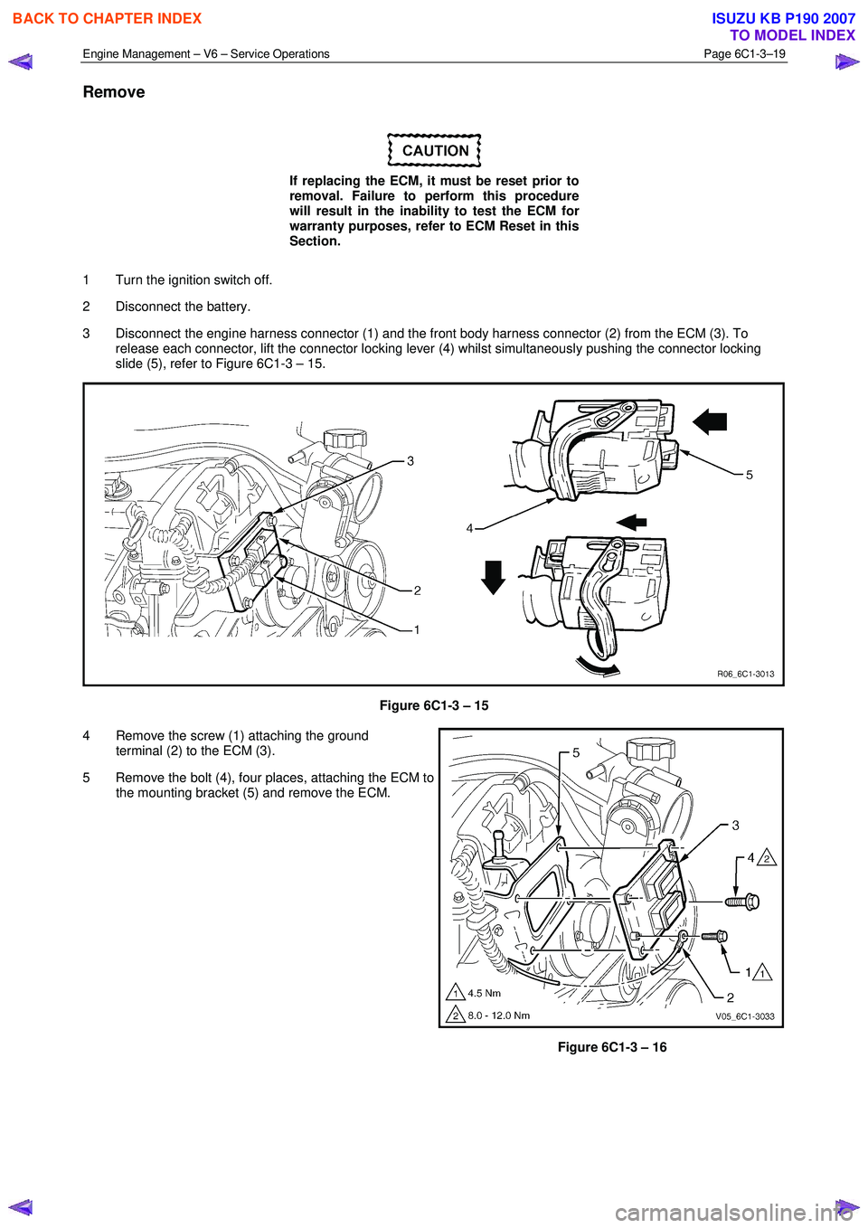
3 Disconnect the engine harness connector (1) and the front body harness connector (2) from the ECM (3). To release each connector, lift the connector locking lever (4) whilst simultaneously pushing the connector locking
slide (5), refer to Figure 6C1-3 – 15.
Figure 6C1-3 – 15
4 Remove the screw (1) attaching the ground terminal (2) to the ECM (3).
5 Remove the bolt (4), four places, attaching the ECM to the mounting bracket (5) and remove the ECM.
Figure 6C1-3 – 16
BACK TO CHAPTER INDEX
TO MODEL INDEX
ISUZU KB P190 2007
Page 3544 of 6020
Engine Management – V6 – Service Operations Page 6C1-3–20
Reinstall
Reinstallation of the engine control module (ECM) is the reverse of the removal procedure, noting the following:
NOTE
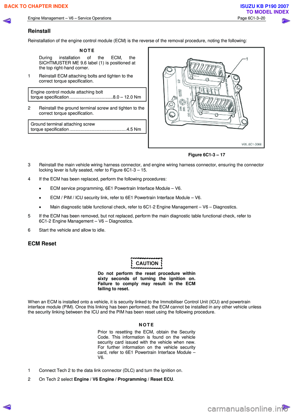
During installation of the ECM, the
SICHTMUSTER ME 9.6 label (1) is positioned at
the top right-hand corner.
1 Reinstall ECM attaching bolts and tighten to the correct torque specification.
Engine control module attaching bolt
torque specification ...................................8.0 – 12.0 Nm
2 Reinstall the ground terminal screw and tighten to the correct torque specification.
Ground terminal attaching screw
torque specification ..............................................4.5 Nm
Figure 6C1-3 – 17
3 Reinstall the main vehicle wiring harness connector, and engine wiring harness connector, ensuring the connector locking lever is fully seated, refer to Figure 6C1-3 – 15.
4 If the ECM has been replaced, perform the following procedures:
• ECM service programming, 6E1 Powertrain Interface Module – V6.
• ECM / PIM / ICU security link, refer to 6E1 Powertrain Interface Module – V6.
• Main diagnostic table functional check, refer to 6C1-2 Engine Management – V6 – Diagnostics.
5 If the ECM has been removed, but not replaced, perform the main diagnostic table functional check, refer to 6C1-2 Engine Management – V6 – Diagnostics.
6 Start the vehicle and allow to idle.
ECM Reset
Do not perform the reset procedure within
sixty seconds of turning the ignition on.
Failure to comply may result in the ECM
failing to reset.
W hen an ECM is installed onto a vehicle, it is security linked to the Immobiliser Control Unit (ICU) and powertrain
interface module (PIM). Once this linking has been performed, the ECM cannot be installed in any other vehicle unless
the security linking between the ICU and the PIM has been reset using the following procedure.
NOTE
Prior to resetting the ECM, obtain the Security
Code. This information is found on the vehicle
security card issued with the vehicle when new.
For further information on the vehicle security
card, refer to 6E1 Powertrain Interface Module –
V6.
1 Connect Tech 2 to the data link connector (DLC) and turn the ignition on.
2 On Tech 2 select Engine / V6 Engine / Programming / Reset ECU .
BACK TO CHAPTER INDEX
TO MODEL INDEX
ISUZU KB P190 2007