2007 ISUZU KB P190 reset
[x] Cancel search: resetPage 3741 of 6020
Powertrain Interface Module – V6 Page 6E1–80
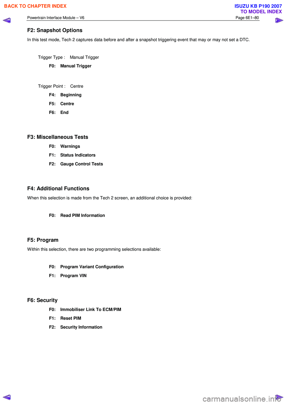
F2: Snapshot Options
In this test mode, Tech 2 captures data before and after a snapshot triggering event that may or may not set a DTC.
Trigger Type : Manual Trigger
F0: Manual Trigger
Trigger Point : Centre
F4: Beginning
F5: Centre
F6: End
F3: Miscellaneous Tests
F0: Warnings
F1: Status Indicators
F2: Gauge Control Tests
F4: Additional Functions
W hen this selection is made from the Tech 2 screen, an additional choice is provided:
F0: Read PIM Information
F5: Program
W ithin this selection, there are two programming selections available:
F0: Program Variant Configuration
F1: Program VIN
F6: Security
F0: Immobiliser Link To ECM/PIM
F1: Reset PIM
F2: Security Information
BACK TO CHAPTER INDEX
TO MODEL INDEX
ISUZU KB P190 2007
Page 3744 of 6020
Powertrain Interface Module – V6 Page 6E1–83
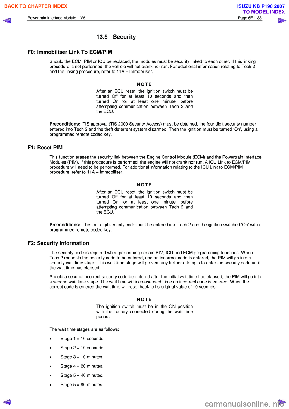
13.5 Security
F0: Immobiliser Link To ECM/PIM
Should the ECM, PIM or ICU be replaced, the modules must be security linked to each other. If this linking
procedure is not performed, the vehicle will not crank nor run. For additional information relating to Tech 2
and the linking procedure, refer to 11A – Immobiliser.
NOTE
After an ECU reset, the ignition switch must be
turned Off for at least 10 seconds and then
turned On for at least one minute, before
attempting communication between Tech 2 and
the ECU.
Preconditions: TIS approval (TIS 2000 Security Access) must be obtained, the four digit security number
entered into Tech 2 and the theft deterrent system disarmed. Then the ignition must be turned ‘On’, using a
programmed remote coded key.
F1: Reset PIM
This function erases the security link between the Engine Control Module (ECM) and the Powertrain Interface Modules (PIM). If this procedure is performed, the engine will not crank nor run. A ICU Link to ECM/PIM
procedure will need to be performed. For additional information relating to the ICU Link to ECM/PIM
procedure, refer to 11A – Immobiliser.
NOTE
After an ECU reset, the ignition switch must be
turned Off for at least 10 seconds and then
turned On for at least one minute, before
attempting communication between Tech 2 and
the ECU.
Preconditions: The four digit security code must be entered into Tech 2 and the ignition switched ‘On’ with a
programmed remote coded key.
F2: Security Information
The security code is required when performing certain PIM, ICU and ECM programming functions. W hen Tech 2 requests the security code to be entered, and an incorrect code is entered, the PIM will go into a
security wait time stage. This wait time stage will prevent any further attempts to enter the security code until
the wait time has elapsed.
Should a second incorrect security code be entered after the initial wait time has elapsed, the PIM will go into a second wait time stage. The wait time will increase each time an incorrect code is entered. W hen the
correct code is entered the wait time will reset back to its original value of 10 seconds.
NOTE
The ignition switch must be in the ON position
with the battery connected during the wait time
period.
The wait time stages are as follows: • Stage 1 = 10 seconds.
• Stage 2 = 10 seconds.
• Stage 3 = 10 minutes.
• Stage 4 = 20 minutes.
• Stage 5 = 40 minutes.
• Stage 5 = 80 minutes.
BACK TO CHAPTER INDEX
TO MODEL INDEX
ISUZU KB P190 2007
Page 3745 of 6020
Powertrain Interface Module – V6 Page 6E1–84
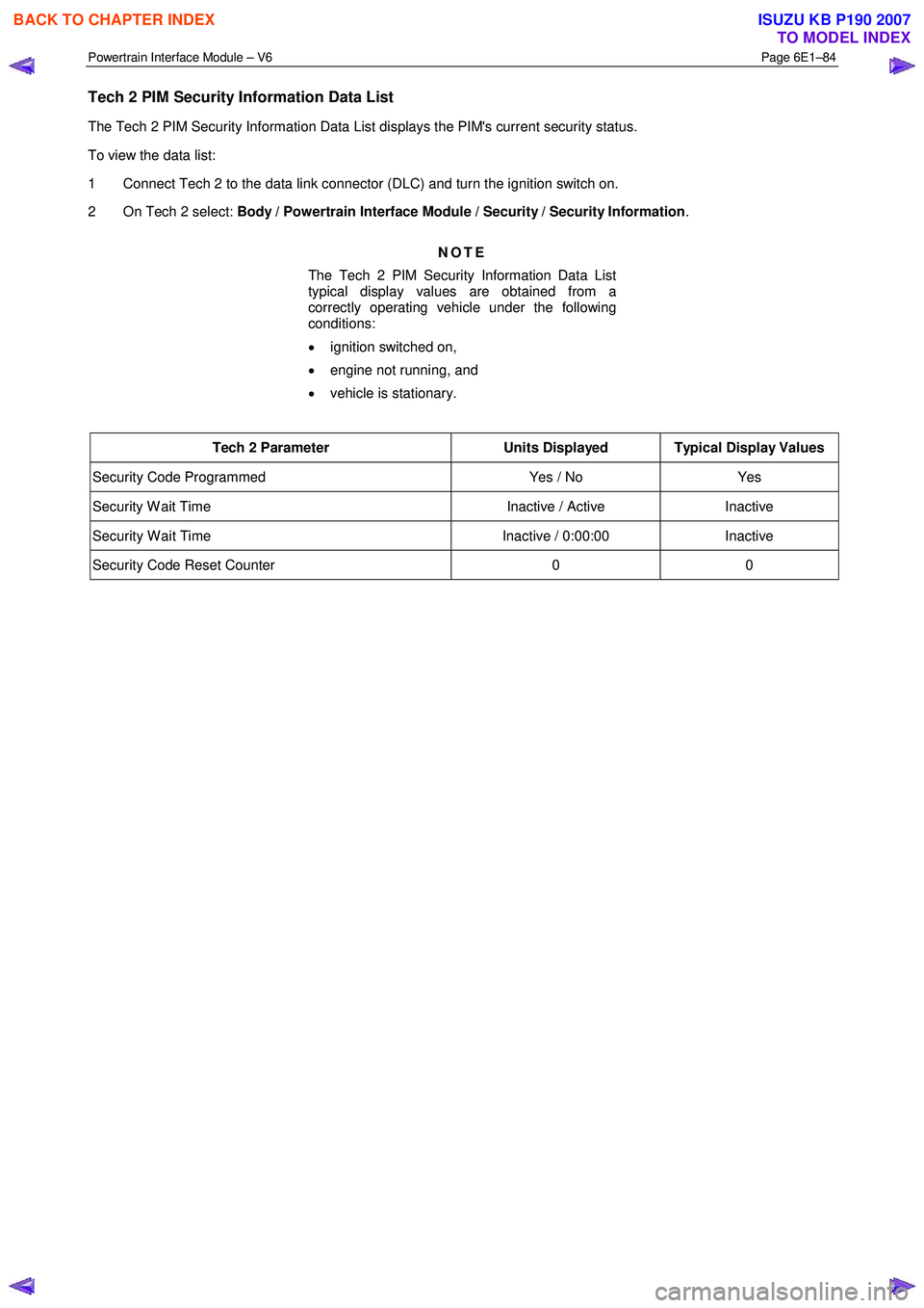
Tech 2 PIM Security Information Data List
The Tech 2 PIM Security Information Data List displays the PIM's current security status.
To view the data list:
1 Connect Tech 2 to the data link connector (DLC) and turn the ignition switch on.
2 On Tech 2 select: Body / Powertrain Interface Module / Security / Security Information .
NOTE
The Tech 2 PIM Security Information Data List
typical display values are obtained from a
correctly operating vehicle under the following
conditions:
• ignition switched on,
• engine not running, and
• vehicle is stationary.
Tech 2 Parameter Units Displayed Typical Display Values
Security Code Programmed Yes / No Yes
Security W ait Time Inactive / Active Inactive
Security W ait Time Inactive / 0:00:00 Inactive
Security Code Reset Counter 0 0
BACK TO CHAPTER INDEX
TO MODEL INDEX
ISUZU KB P190 2007
Page 3802 of 6020
Automatic Transmission – 4L60E – Electrical Diagnosis Page 7C2–16
Programming
If Programming is selected, a selection list is displayed which contains:
• Reset TAP Cells – This test allows the user to reset the Transmission Adapt (TAP) cells by pressing the Reset soft
key.
NOTE
Upon resetting the TAP cells the TCM loses all
learnt adaptive functions. When the vehicle is first
driven after this, the shifts may be harsh. This
harshness will ease as the TCM relearns the TAP
cells.
3.2 Data Display
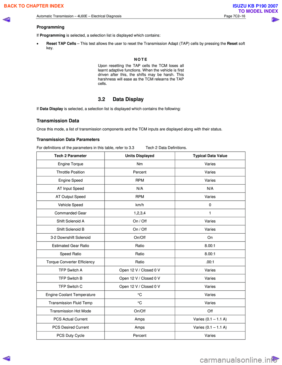
If Data Display is selected, a selection list is displayed which contains the following:
Transmission Data
Once this mode, a list of transmission components and the TCM inputs are displayed along with their status.
Transmission Data Parameters
For definitions of the parameters in this table, refer to 3.3 Tech 2 Data Definitions.
Tech 2 Parameter Units Displayed Typical Data Value
Engine Torque Nm Varies
Throttle Position Percent Varies
Engine Speed RPM Varies
AT Input Speed N/A N/A
AT Output Speed RPM Varies
Vehicle Speed km/h 0
Commanded Gear 1,2,3,4 1
Shift Solenoid A On / Off Varies
Shift Solenoid B On / Off Varies
3-2 Downshift Solenoid On/Off On
Estimated Gear Ratio Ratio 8.00:1
Speed Ratio Ratio 8.00:1
Torque Converter Efficiency Ratio .00:1
TFP Switch A Open 12 V / Closed 0 V Varies
TFP Switch B Open 12 V / Closed 0 V Varies
TFP Switch C Open 12 V / Closed 0 V Varies
Engine Coolant Temperature °C Varies
Transmission Fluid Temp °C Varies
Transmission Hot Mode On/Off Off
PCS Actual Current Amps Varies (0.1 – 1.1 A)
PCS Desired Current Amps Varies (0.1 – 1.1 A)
PCS Duty Cycle Percent Varies
BACK TO CHAPTER INDEX
TO MODEL INDEX
ISUZU KB P190 2007
Page 3810 of 6020
Automatic Transmission – 4L60E – Electrical Diagnosis Page 7C2–24
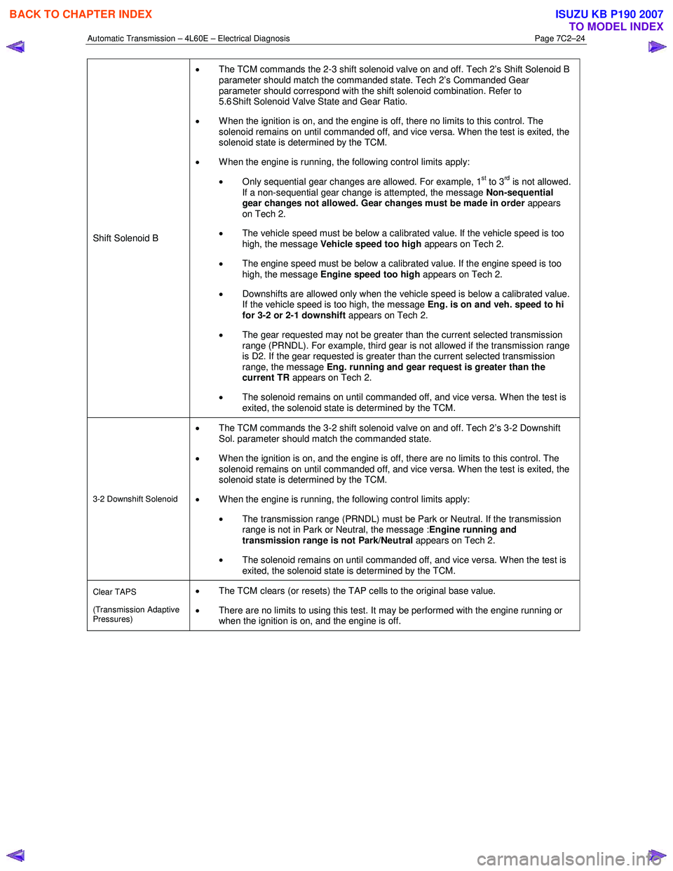
Shift Solenoid B •
The TCM commands the 2-3 shift solenoid valve on and off. Tech 2’s Shift Solenoid B
parameter should match the commanded state. Tech 2’s Commanded Gear
parameter should correspond with the shift solenoid combination. Refer to
5.6 Shift Solenoid Valve State and Gear Ratio.
• When the ignition is on, and the engine is off, there no limits to this control. The
solenoid remains on until commanded off, and vice versa. W hen the test is exited, the
solenoid state is determined by the TCM.
• W hen the engine is running, the following control limits apply:
• Only sequential gear changes are allowed. For example, 1
st to 3rd is not allowed.
If a non-sequential gear change is attempted, the message Non-sequential
gear changes not allowed. Gear changes must be made in order appears
on Tech 2.
• The vehicle speed must be below a calibrated value. If the vehicle speed is too
high, the message Vehicle speed too high appears on Tech 2.
• The engine speed must be below a calibrated value. If the engine speed is too
high, the message Engine speed too high appears on Tech 2.
• Downshifts are allowed only when the vehicle speed is below a calibrated value.
If the vehicle speed is too high, the message Eng. is on and veh. speed to hi
for 3-2 or 2-1 downshift appears on Tech 2.
• The gear requested may not be greater than the current selected transmission
range (PRNDL). For example, third gear is not allowed if the transmission range
is D2. If the gear requested is greater than the current selected transmission
range, the message Eng. running and gear request is greater than the
current TR appears on Tech 2.
• The solenoid remains on until commanded off, and vice versa. W hen the test is
exited, the solenoid state is determined by the TCM.
3-2 Downshift Solenoid
• The TCM commands the 3-2 shift solenoid valve on and off. Tech 2’s 3-2 Downshift
Sol. parameter should match the commanded state.
• When the ignition is on, and the engine is off, there are no limits to this control. The
solenoid remains on until commanded off, and vice versa. W hen the test is exited, the
solenoid state is determined by the TCM.
• W hen the engine is running, the following control limits apply:
• The transmission range (PRNDL) must be Park or Neutral. If the transmission
range is not in Park or Neutral, the message : Engine running and
transmission range is not Park/Neutral appears on Tech 2.
• The solenoid remains on until commanded off, and vice versa. W hen the test is
exited, the solenoid state is determined by the TCM.
Clear TAPS
(Transmission Adaptive
Pressures) • The TCM clears (or resets) the TAP cells to the original base value.
• There are no limits to using this test. It may be performed with the engine running or
when the ignition is on, and the engine is off.
BACK TO CHAPTER INDEX
TO MODEL INDEX
ISUZU KB P190 2007
Page 3826 of 6020
Automatic Transmission – 4L60E – Electrical Diagnosis Page 7C2–40
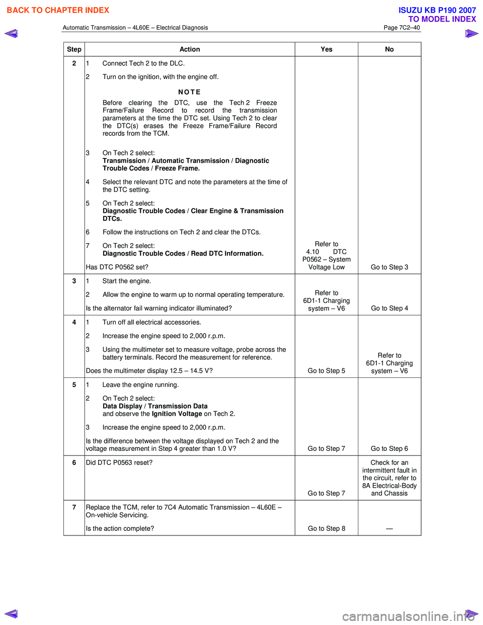
Step Action Yes No
2 1 Connect Tech 2 to the DLC.
2 Turn on the ignition, with the engine off.
NOTE
Before clearing the DTC, use the Tech 2 Freeze
Frame/Failure Record to record the transmission
parameters at the time the DTC set. Using Tech 2 to clear
the DTC(s) erases the Freeze Frame/Failure Record
records from the TCM.
3 On Tech 2 select: Transmission / Automatic Transmission / Diagnostic
Trouble Codes / Freeze Frame.
4 Select the relevant DTC and note the parameters at the time of the DTC setting.
5 On Tech 2 select:
Diagnostic Trouble Codes / Clear Engine & Transmission
DTCs.
6 Follow the instructions on Tech 2 and clear the DTCs.
7 On Tech 2 select: Diagnostic Trouble Codes / Read DTC Information.
Has DTC P0562 set? Refer to
4.10 DTC
P0562 – System
Voltage Low Go to Step 3
3 1 Start the engine.
2 Allow the engine to warm up to normal operating temperature.
Is the alternator fail warning indicator illuminated? Refer to
6D1-1 Charging system – V6 Go to Step 4
4 1 Turn off all electrical accessories.
2 Increase the engine speed to 2,000 r.p.m.
3 Using the multimeter set to measure voltage, probe across the battery terminals. Record the measurement for reference.
Does the multimeter display 12.5 – 14.5 V? Go to Step 5 Refer to
6D1-1 Charging system – V6
5 1 Leave the engine running.
2 On Tech 2 select: Data Display / Transmission Data
and observe the Ignition Voltage on Tech 2.
3 Increase the engine speed to 2,000 r.p.m.
Is the difference between the voltage displayed on Tech 2 and the
voltage measurement in Step 4 greater than 1.0 V? Go to Step 7 Go to Step 6
6 Did DTC P0563 reset?
Go to Step 7 Check for an
intermittent fault in the circuit, refer to
8A Electrical-Body and Chassis
7 Replace the TCM, refer to 7C4 Automatic Transmission – 4L60E –
On-vehicle Servicing.
Is the action complete? Go to Step 8 —
BACK TO CHAPTER INDEX
TO MODEL INDEX
ISUZU KB P190 2007
Page 3827 of 6020
Automatic Transmission – 4L60E – Electrical Diagnosis Page 7C2–41
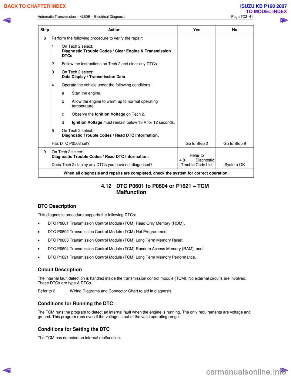
Step Action Yes No
8 Perform the following procedure to verify the repair:
1 On Tech 2 select: Diagnostic Trouble Codes / Clear Engine & Transmission
DTCs
2 Follow the instructions on Tech 2 and clear any DTCs.
3 On Tech 2 select: Data Display / Transmission Data
4 Operate the vehicle under the following conditions: a Start the engine.
b Allow the engine to warm up to normal operating temperature.
c Observe the Ignition Voltage on Tech 2.
d Ignition Voltage must remain below 18 V for 12 seconds.
5 On Tech 2 select:
Diagnostic Trouble Codes / Read DTC Information.
Has DTC P0563 set? Go to Step 2 Go to Step 9
9 On Tech 2 select:
Diagnostic Trouble Codes / Read DTC Information.
Does Tech 2 display any DTCs you have not diagnosed? Refer to
4.8 Diagnostic Trouble Code List System OK
When all diagnosis and repairs are completed, check the
system for correct operation.
4.12 DTC P0601 to P0604 or P1621 – TCM
Malfunction
DTC Description
This diagnostic procedure supports the following DTCs:
• DTC P0601 Transmission Control Module (TCM) Read Only Memory (ROM),
• DTC P0602 Transmission Control Module (TCM) Not Programmed,
• DTC P0603 Transmission Control Module (TCM) Long Term Memory Reset,
• DTC P0604 Transmission Control Module (TCM) Random Access Memory (RAM), and
• DTC P1621 Transmission Control Module (TCM) Long Term Memory Performance.
Circuit Description
The internal fault detection is handled inside the transmission control module (TCM). No external circuits are involved.
These DTCs are type A DTCs.
Refer to 2 W iring Diagrams and Connector Chart to aid in diagnosis.
Conditions for Running the DTC
The TCM runs the program to detect an internal fault when the engine is running. The only requirements are voltage and
ground. This program runs even if the voltage is out of the valid operating range.
Conditions for Setting the DTC
The TCM has detected an internal malfunction.
BACK TO CHAPTER INDEX
TO MODEL INDEX
ISUZU KB P190 2007
Page 3850 of 6020
Automatic Transmission – 4L60E – Electrical Diagnosis Page 7C2–64
Diagnostic Aids
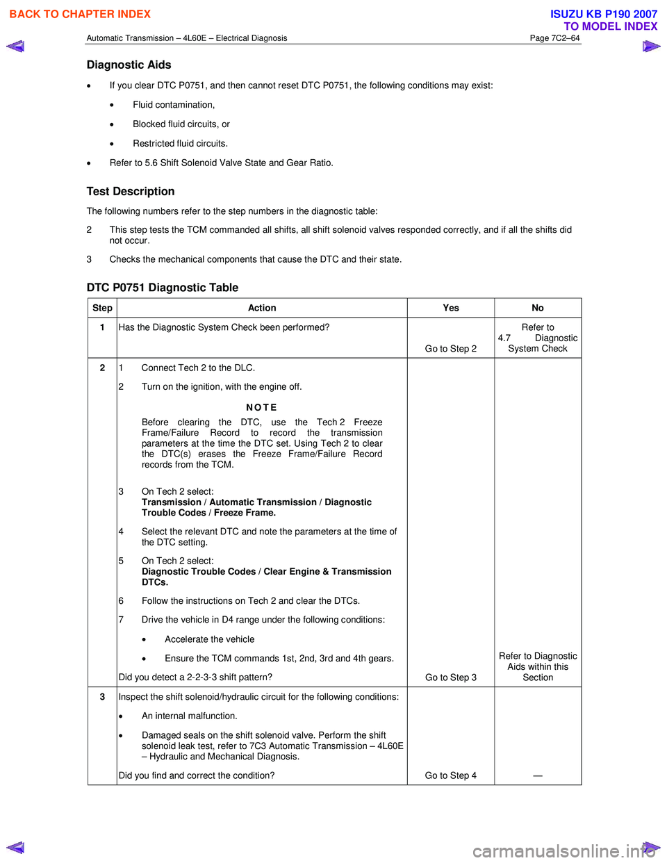
• If you clear DTC P0751, and then cannot reset DTC P0751, the following conditions may exist:
• Fluid contamination,
• Blocked fluid circuits, or
• Restricted fluid circuits.
• Refer to 5.6 Shift Solenoid Valve State and Gear Ratio.
Test Description
The following numbers refer to the step numbers in the diagnostic table:
2 This step tests the TCM commanded all shifts, all shift solenoid valves responded correctly, and if all the shifts did not occur.
3 Checks the mechanical components that cause the DTC and their state.
DTC P0751 Diagnostic Table
Step Action Yes No
1 Has the Diagnostic System Check been performed?
Go to Step 2 Refer to
4.7 Diagnostic System Check
2 1 Connect Tech 2 to the DLC.
2 Turn on the ignition, with the engine off.
NOTE
Before clearing the DTC, use the Tech 2 Freeze
Frame/Failure Record to record the transmission
parameters at the time the DTC set. Using Tech 2 to clear
the DTC(s) erases the Freeze Frame/Failure Record
records from the TCM.
3 On Tech 2 select: Transmission / Automatic Transmission / Diagnostic
Trouble Codes / Freeze Frame.
4 Select the relevant DTC and note the parameters at the time of the DTC setting.
5 On Tech 2 select:
Diagnostic Trouble Codes / Clear Engine & Transmission
DTCs.
6 Follow the instructions on Tech 2 and clear the DTCs.
7 Drive the vehicle in D4 range under the following conditions:
• Accelerate the vehicle
• Ensure the TCM commands 1st, 2nd, 3rd and 4th gears.
Did you detect a 2-2-3-3 shift pattern? Go to Step 3 Refer to Diagnostic
Aids within this Section
3 Inspect the shift solenoid/hydraulic circuit for the following conditions:
• An internal malfunction.
• Damaged seals on the shift solenoid valve. Perform the shift
solenoid leak test, refer to 7C3 Automatic Transmission – 4L60E
– Hydraulic and Mechanical Diagnosis.
Did you find and correct the condition? Go to Step 4 —
BACK TO CHAPTER INDEX
TO MODEL INDEX
ISUZU KB P190 2007