2007 ISUZU KB P190 reset
[x] Cancel search: resetPage 5215 of 6020
ELECTRICAL-BODY AND CHASSIS 8A-277
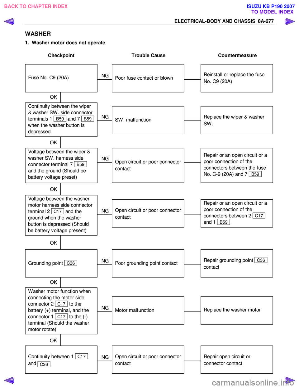
WASHER
1. Washer motor does not operate
Checkpoint Trouble Cause Countermeasure
Reinstall or replace the fuse
No. C9 (20A)
Poor fuse contact or blown
NG
Repair or an open circuit or a
poor connection of the
connectors between 2
C17
and 1
B59
Open circuit or poor connector
contact
NG Voltage between the washer
motor harness side connector
terminal 2
C17 and the
ground when the washer
button is depressed (Should
be battery v oltage present)
Repair grounding point
C36
contact
Poor grounding point contact
NG
Grounding point
C36
Replace the washer motor
Motor malfunction
NG
W asher motor function when
connecting the motor side
connector 2
C17 to the
battery (+) terminal, and the
connector 1
C17 to the (-)
terminal (Should the washer
motor rotate) OK
Repair open circuit or
connector contact
Open circuit or poor connector
contact
NG
Continuity between 1
C17
and
C36
OK
Continuity between the wiper
& washer SW . side connector
terminals 1
B59 and 7 B59
when the washer button is
depressed
Fuse No. C9 (20A)
OK
Replace the wiper & washer
SW .
SW . malfunction
NG
Repair or an open circuit or a
poor connection of the
connectors between the fuse
No. C-9 (20A) and 7
B59
Voltage between the wiper &
washer SW . harness side
connector terminal 7
B59
and the ground (Should be
battery v oltage preset)
Open circuit or poor connector
contact
NG
OK
OK
OK
BACK TO CHAPTER INDEX
TO MODEL INDEXISUZU KB P190 2007
Page 5282 of 6020
8A-344 ELECTRICAL-BODY AND CHASSIS
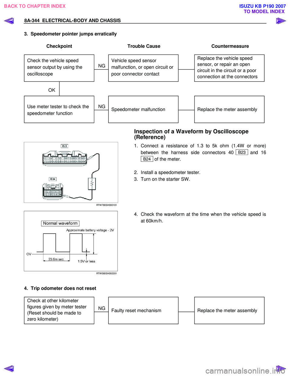
3. Speedometer pointer jumps erratically
Checkpoint Trouble Cause Countermeasure
Replace the vehicle speed
sensor, or repair an open
circuit in the circuit or a poor
connection at the connectors Vehicle speed sensor
malfunction, or open circuit or
poor connector contact
NG
Replace the meter assembly
Use meter tester to check the
speedometer function
Speedometer malfunction
NG
OK
Check the vehicle speed
sensor output by using the
oscilloscope
Inspection of a Waveform by Oscilloscope
(Reference)
RTW 780SH000101
1. Connect a resistance of 1.3 to 5k ohm (1.4W or more)
between the harness side connectors 40
B23 and 16
B24 of the meter.
2. Install a speedometer tester.
3. Turn on the starter SW .
RTW 580SH002201
4. Check the waveform at the time when the vehicle speed is
at 60km/h.
4. Trip odometer does not reset
Replace the meter assembly
Faulty reset mechanism
NG
Check at other kilometer
figures given by meter tester
(Reset should be made to
zero kilometer)
BACK TO CHAPTER INDEX
TO MODEL INDEXISUZU KB P190 2007
Page 5300 of 6020
8A-362 ELECTRICAL-BODY AND CHASSIS
Tachometer Off-Vehicle Inspection
Remove the tachometer from the meter assembly and
measure the resistance value and the current consumption
between each terminal.
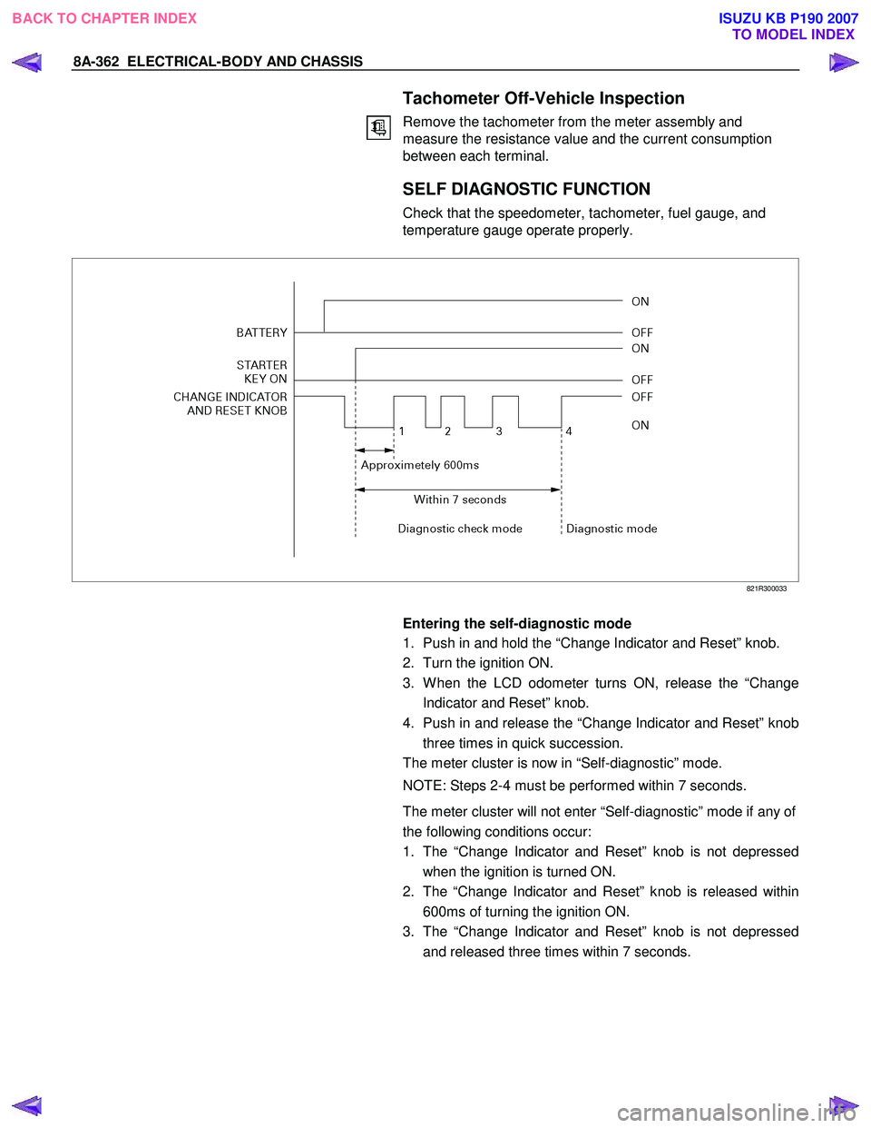
SELF DIAGNOSTIC FUNCTION
Check that the speedometer, tachometer, fuel gauge, and
temperature gauge operate properly.
821R300033
Entering the self-diagnostic mode
1. Push in and hold the “Change Indicator and Reset” knob.
2. Turn the ignition ON.
3. W hen the LCD odometer turns ON, release the “Change Indicator and Reset” knob.
4. Push in and release the “Change Indicator and Reset” knob three times in quick succession.
The meter cluster is now in “Self-diagnostic” mode.
NOTE: Steps 2-4 must be performed within 7 seconds.
The meter cluster will not enter “Self-diagnostic” mode if any of
the following conditions occur:
1. The “Change Indicator and Reset” knob is not depressed when the ignition is turned ON.
2. The “Change Indicator and Reset” knob is released within 600ms of turning the ignition ON.
3. The “Change Indicator and Reset” knob is not depressed and released three times within 7 seconds.
BACK TO CHAPTER INDEX TO MODEL INDEXISUZU KB P190 2007
Page 5301 of 6020
ELECTRICAL-BODY AND CHASSIS 8A-363
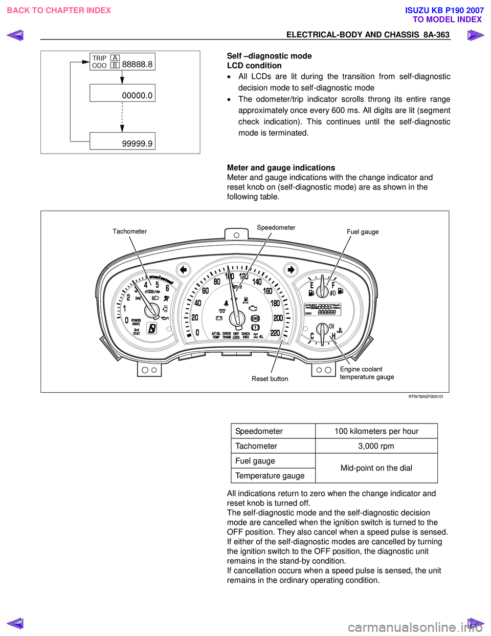
Self –diagnostic mode
LCD condition
• All LCDs are lit during the transition from self-diagnostic
decision mode to self-diagnostic mode
• The odometer/trip indicator scrolls throng its entire range
approximately once every 600 ms. All digits are lit (segment
check indication). This continues until the self-diagnostic
mode is terminated.
Meter and gauge indications
Meter and gauge indications with the change indicator and
reset knob on (self-diagnostic mode) are as shown in the
following table.
RTW 78ASF000101
Speedometer 100 kilometers per hour
Tachometer 3,000 rpm
Fuel gauge
Temperature gauge Mid-point on the dial
All indications return to zero when the change indicator and
reset knob is turned off.
The self-diagnostic mode and the self-diagnostic decision
mode are cancelled when the ignition switch is turned to the
OFF position. They also cancel when a speed pulse is sensed.
If either of the self-diagnostic modes are cancelled by turning
the ignition switch to the OFF position, the diagnostic unit
remains in the stand-by condition.
If cancellation occurs when a speed pulse is sensed, the unit
remains in the ordinary operating condition.
BACK TO CHAPTER INDEX TO MODEL INDEXISUZU KB P190 2007
Page 5852 of 6020
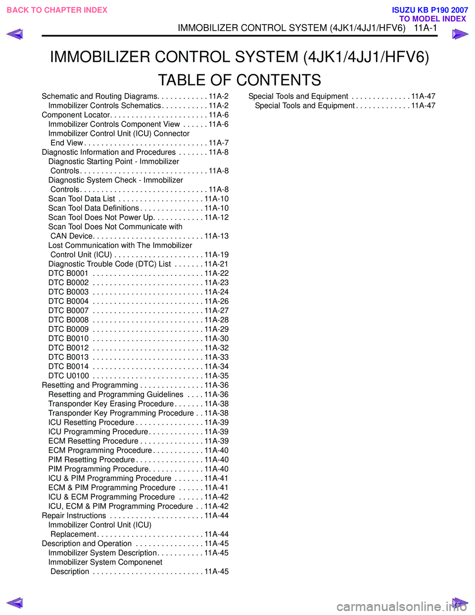
IMMOBILIZER CONTROL SYSTEM (4JK1/4JJ1/HFV6)TABLE OF CONTENTS
Schematic and Routing Diagrams. . . . . . . . . . . . 11A-2Immobilizer Controls Schematics . . . . . . . . . . . 11A-2
Component Locator. . . . . . . . . . . . . . . . . . . . . . . 11A-6 Immobilizer Controls Component View . . . . . . 11A-6
Immobilizer Control Unit (ICU) Connector End View . . . . . . . . . . . . . . . . . . . . . . . . . . . . . 11A-7
Diagnostic Information and Procedures . . . . . . . 11A-8 Diagnostic Starting Point - Immobilizer Controls . . . . . . . . . . . . . . . . . . . . . . . . . . . . . . 11A-8
Diagnostic System Check - Immobilizer Controls . . . . . . . . . . . . . . . . . . . . . . . . . . . . . . 11A-8
Scan Tool Data List . . . . . . . . . . . . . . . . . . . . 11A-10
Scan Tool Data Definitions . . . . . . . . . . . . . . . 11A-10
Scan Tool Does Not Power Up. . . . . . . . . . . . 11A-12
Scan Tool Does Not Communicate with CAN Device. . . . . . . . . . . . . . . . . . . . . . . . . . 11A-13
Lost Communication with The Immobilizer Control Unit (ICU) . . . . . . . . . . . . . . . . . . . . . 11A-19
Diagnostic Trouble Code (DTC) List . . . . . . . 11A-21
DTC B0001 . . . . . . . . . . . . . . . . . . . . . . . . . . 11A-22
DTC B0002 . . . . . . . . . . . . . . . . . . . . . . . . . . 11A-23
DTC B0003 . . . . . . . . . . . . . . . . . . . . . . . . . . 11A-24
DTC B0004 . . . . . . . . . . . . . . . . . . . . . . . . . . 11A-26
DTC B0007 . . . . . . . . . . . . . . . . . . . . . . . . . . 11A-27
DTC B0008 . . . . . . . . . . . . . . . . . . . . . . . . . . 11A-28
DTC B0009 . . . . . . . . . . . . . . . . . . . . . . . . . . 11A-29
DTC B0010 . . . . . . . . . . . . . . . . . . . . . . . . . . 11A-30
DTC B0012 . . . . . . . . . . . . . . . . . . . . . . . . . . 11A-32
DTC B0013 . . . . . . . . . . . . . . . . . . . . . . . . . . 11A-33
DTC B0014 . . . . . . . . . . . . . . . . . . . . . . . . . . 11A-34
DTC U0100 . . . . . . . . . . . . . . . . . . . . . . . . . . 11A-35
Resetting and Programming . . . . . . . . . . . . . . . 11A-36 Resetting and Programming Guidelines . . . . 11A-36
Transponder Key Erasing Procedure . . . . . . . 11A-38
Transponder Key Programming Procedure . . 11A-38
ICU Resetting Procedure . . . . . . . . . . . . . . . . 11A-39
ICU Programming Procedure . . . . . . . . . . . . . 11A-39
ECM Resetting Procedure . . . . . . . . . . . . . . . 11A-39
ECM Programming Procedure . . . . . . . . . . . . 11A-40
PIM Resetting Procedure . . . . . . . . . . . . . . . . 11A-40
PIM Programming Procedure. . . . . . . . . . . . . 11A-40
ICU & PIM Programming Procedure . . . . . . . 11A-41
ECM & PIM Programming Procedure . . . . . . 11A-41
ICU & ECM Programming Procedure . . . . . . 11A-42
ICU, ECM & PIM Programming Procedure . . 11A-42
Repair Instructions . . . . . . . . . . . . . . . . . . . . . . 11A-44 Immobilizer Control Unit (ICU) Replacement . . . . . . . . . . . . . . . . . . . . . . . . . 11A-44
Description and Operation . . . . . . . . . . . . . . . . 11A-45 Immobilizer System Description . . . . . . . . . . . 11A-45
Immobilizer System Componenet Description . . . . . . . . . . . . . . . . . . . . . . . . . . 11A-45 Special Tools and Equipment . . . . . . . . . . . . . . 11A-47
Special Tools and Equipment . . . . . . . . . . . . . 11A-47
IM MOBI LIZER CONTR OL SY STEM (4JK 1/4 JJ1/ HFV 6) 1 1A- 1
BACK TO CHAPTER INDEX
TO MODEL INDEX
ISUZU KB P190 2007
Page 5874 of 6020

IMMOBILIZER CONTROL SYSTEM (4JK1/4JJ1/HFV6) 11A-23
DTC B0002
Description
The electrically erasable programmable read only
memory (EEPROM) memorizes immobilizer security
code and transponder key information. If the ICU
detects immobilizer security code is not programmed
into the ICU, this DTC will set.
Condition for Setting the DTC • The ICU detects that the security code is not programmed.
Action Taken When the DTC Sets • The engine will fail to run if the fault occurs before starting the engine. Condition for Clearing the DTC
• A current DTC clears once ignition cycle has occurred without the fault recurring.
• A history DTC will clear after 50 consecutive ignition cycles, if the condition for malfunction is no
longer present.
• Use a scan tool to clear the DTC.
Diagnostic Aids • Non-programmed ICU sets this DTC.
Circuit/ System Testing DTC B0002
Step Action Value(s)Yes No
1 Did you perform the Diagnostic System Check -
Immobilizer Controls? —
Go to Step 2 Go to Diagnostic
System Check - Immobilizer Controls
2 1. Install a scan tool.
2. Turn OFF the ignition for 30 seconds.
3. Turn ON the ignition, with the engine OFF.
4. Monitor the DTC Information with a scan tool.
Does the DTC fail this ignition? —
Go to Step 3 Go to Diagnostic
Aids
3 Program immobilizer security information into the
ICU. Refer to Resetting and Programming
Guidelines in this section.
Did you complete the programming? —
Go to Step 4
—
41. Clear the DTCs with a scan tool.
2. Turn OFF the ignition for 30 seconds.
3. Turn ON the ignition.
Did the DTC fail this ignition? —
Go to Step 3 Go to Step 5
5 Observe the DTC Information with a scan tool.
Are there any DTCs that you have not diagnosed? —
Go to DTC List System OK
BACK TO CHAPTER INDEX
TO MODEL INDEX
ISUZU KB P190 2007
Page 5876 of 6020
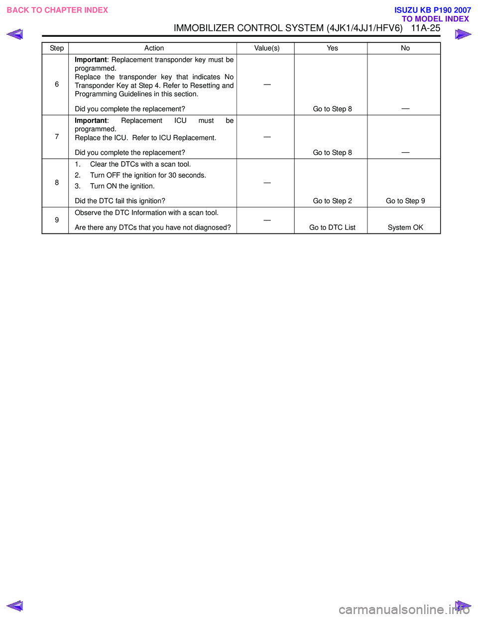
IMMOBILIZER CONTROL SYSTEM (4JK1/4JJ1/HFV6) 11A-25
6Important
: Replacement transponder key must be
programmed.
Replace the transponder key that indicates No
Transponder Key at Step 4. Refer to Resetting and
Programming Guidelines in this section.
Did you complete the replacement? —
Go to Step 8
—
7Important
: Replacement ICU must be
programmed.
Replace the ICU. Refer to ICU Replacement.
Did you complete the replacement? —
Go to Step 8
—
81. Clear the DTCs with a scan tool.
2. Turn OFF the ignition for 30 seconds.
3. Turn ON the ignition.
Did the DTC fail this ignition? —
Go to Step 2 Go to Step 9
9 Observe the DTC Information with a scan tool.
Are there any DTCs that you have not diagnosed? —
Go to DTC List System OK
Step
Action Value(s)Yes No
BACK TO CHAPTER INDEX
TO MODEL INDEX
ISUZU KB P190 2007
Page 5879 of 6020
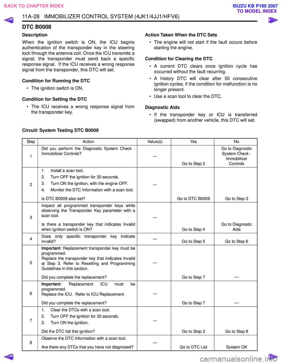
11A-28 IMMOBILIZER CONTROL SYSTEM (4JK1/4JJ1/HFV6)
DTC B0008
Description
When the ignition switch is ON, the ICU begins
authentication of the transponder key in the steering
lock through the antenna coil. Once the ICU transmits a
signal, the transponder must send back a specific
response signal. If the ICU receives a wrong response
signal from the transponder, this DTC will set.
Condition for Running the DTC • The ignition switch is ON.
Condition for Setting the DTC • The ICU receives a wrong response signal from the transponder key. Action Taken When the DTC Sets
• The engine will not start if the fault occurs before starting the engine.
Condition for Clearing the DTC • A current DTC clears once ignition cycle has occurred without the fault recurring.
• A history DTC will clear after 50 consecutive ignition cycles, if the condition for malfunction is no
longer present.
• Use a scan tool to clear the DTC.
Diagnostic Aids • If the transponder key or ICU is transferred (swapped) from another vehicle, this DTC will set.
Circuit/ System Testing DTC B0008
Step Action Value(s)Yes No
1 Did you perform the Diagnostic System Check -
Immobilizer Controls? —
Go to Step 2 Go to Diagnostic
System Check - Immobilizer Controls
2 1. Install a scan tool.
2. Turn OFF the ignition for 30 seconds.
3. Turn ON the ignition, with the engine OFF.
4. Monitor the DTC Information with a scan tool.
Is DTC B0009 also set? —
Go to DTC B0009 Go to Step 3
3 Inspect all programmed transponder keys while
observing the Transponder Key parameter with a
scan tool.
Is there a transponder key that indicates Invalid
when ignition switch is ON? —
Go to Step 4 Go to Diagnostic
Aids
4 Does only specific transponder key indicate
Invalid? —
Go to Step 5 Go to Step 6
5 Important
: Replacement transponder key must be
programmed.
Replace the transponder key that indicates Invalid
at Step 3. Refer to Resetting and Programming
Guidelines in this section.
Did you complete the replacement? —
Go to Step 7
—
6Important
: Replacement ICU must be
programmed.
Replace the ICU. Refer to ICU Replacement.
Did you complete the replacement? —
Go to Step 7
—
71. Clear the DTCs with a scan tool.
2. Turn OFF the ignition for 30 seconds.
3. Turn ON the ignition.
Did the DTC fail this ignition? —
Go to Step 2 Go to Step 8
8 Observe the DTC Information with a scan tool.
Are there any DTCs that you have not diagnosed? —
Go to DTC List System OK
BACK TO CHAPTER INDEX
TO MODEL INDEX
ISUZU KB P190 2007