2007 ISUZU KB P190 reset
[x] Cancel search: resetPage 3852 of 6020
Automatic Transmission – 4L60E – Electrical Diagnosis Page 7C2–66
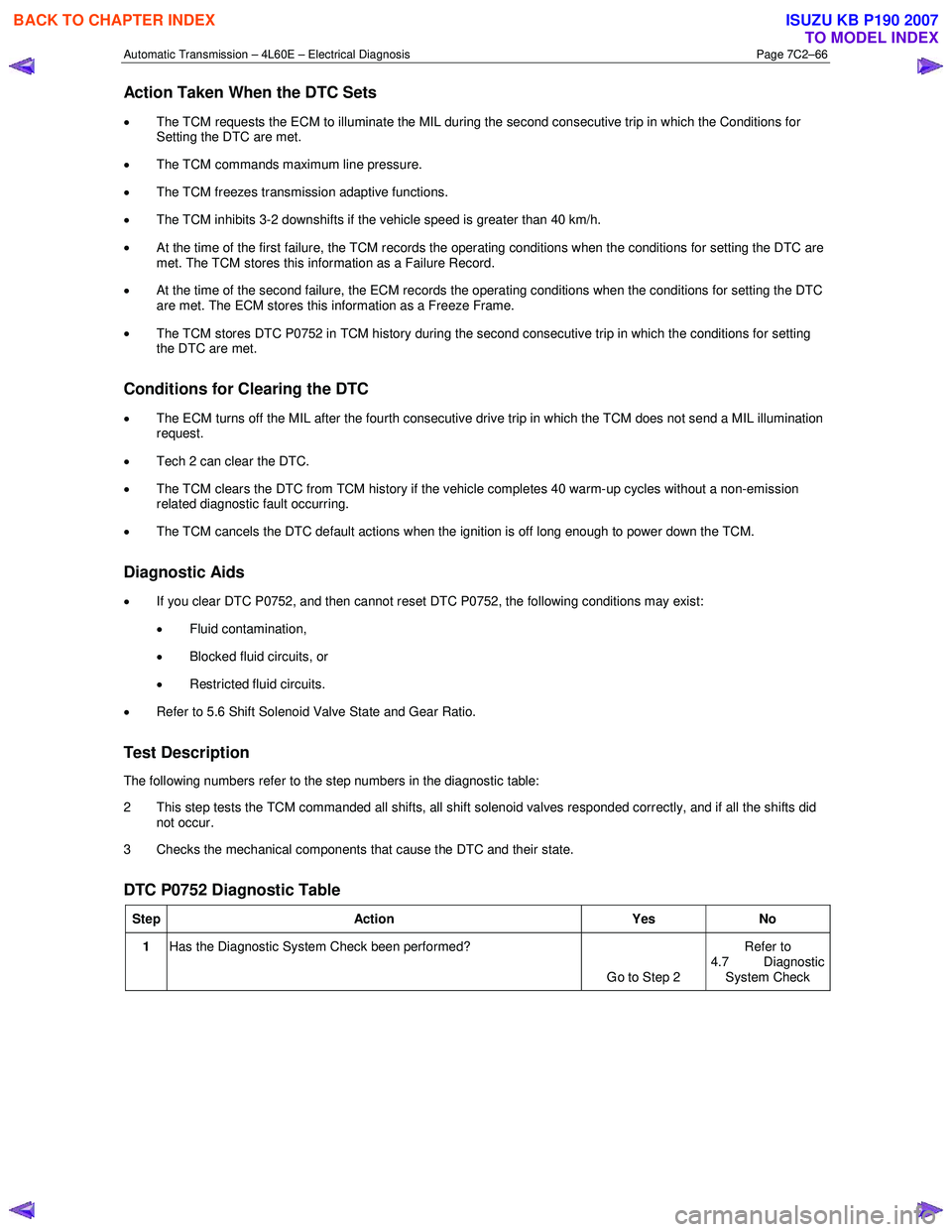
Action Taken When the DTC Sets
• The TCM requests the ECM to illuminate the MIL during the second consecutive trip in which the Conditions for
Setting the DTC are met.
• The TCM commands maximum line pressure.
• The TCM freezes transmission adaptive functions.
• The TCM inhibits 3-2 downshifts if the vehicle speed is greater than 40 km/h.
• At the time of the first failure, the TCM records the operating conditions when the conditions for setting the DTC are
met. The TCM stores this information as a Failure Record.
• At the time of the second failure, the ECM records the operating conditions when the conditions for setting the DTC
are met. The ECM stores this information as a Freeze Frame.
• The TCM stores DTC P0752 in TCM history during the second consecutive trip in which the conditions for setting
the DTC are met.
Conditions for Clearing the DTC
• The ECM turns off the MIL after the fourth consecutive drive trip in which the TCM does not send a MIL illumination
request.
• Tech 2 can clear the DTC.
• The TCM clears the DTC from TCM history if the vehicle completes 40 warm-up cycles without a non-emission
related diagnostic fault occurring.
• The TCM cancels the DTC default actions when the ignition is off long enough to power down the TCM.
Diagnostic Aids
• If you clear DTC P0752, and then cannot reset DTC P0752, the following conditions may exist:
• Fluid contamination,
• Blocked fluid circuits, or
• Restricted fluid circuits.
• Refer to 5.6 Shift Solenoid Valve State and Gear Ratio.
Test Description
The following numbers refer to the step numbers in the diagnostic table:
2 This step tests the TCM commanded all shifts, all shift solenoid valves responded correctly, and if all the shifts did not occur.
3 Checks the mechanical components that cause the DTC and their state.
DTC P0752 Diagnostic Table
Step Action Yes No
1 Has the Diagnostic System Check been performed?
Go to Step 2 Refer to
4.7 Diagnostic
System Check
BACK TO CHAPTER INDEX
TO MODEL INDEX
ISUZU KB P190 2007
Page 3855 of 6020
Automatic Transmission – 4L60E – Electrical Diagnosis Page 7C2–69
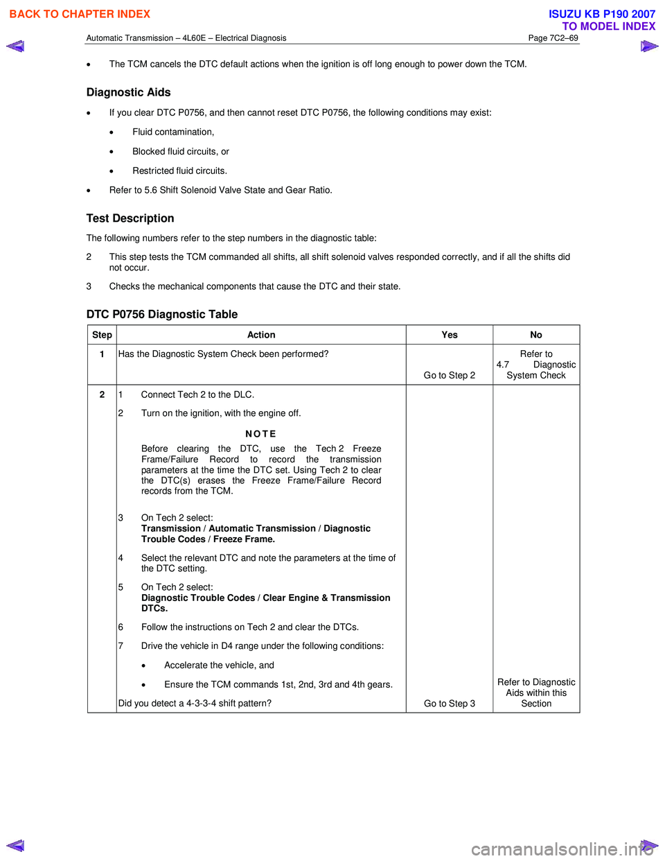
• The TCM cancels the DTC default actions when the ignition is off long enough to power down the TCM.
Diagnostic Aids
•
If you clear DTC P0756, and then cannot reset DTC P0756, the following conditions may exist:
• Fluid contamination,
• Blocked fluid circuits, or
• Restricted fluid circuits.
• Refer to 5.6 Shift Solenoid Valve State and Gear Ratio.
Test Description
The following numbers refer to the step numbers in the diagnostic table:
2 This step tests the TCM commanded all shifts, all shift solenoid valves responded correctly, and if all the shifts did not occur.
3 Checks the mechanical components that cause the DTC and their state.
DTC P0756 Diagnostic Table
Step Action Yes No
1 Has the Diagnostic System Check been performed?
Go to Step 2 Refer to
4.7 Diagnostic System Check
2 1 Connect Tech 2 to the DLC.
2 Turn on the ignition, with the engine off.
NOTE
Before clearing the DTC, use the Tech 2 Freeze
Frame/Failure Record to record the transmission
parameters at the time the DTC set. Using Tech 2 to clear
the DTC(s) erases the Freeze Frame/Failure Record
records from the TCM.
3 On Tech 2 select: Transmission / Automatic Transmission / Diagnostic
Trouble Codes / Freeze Frame.
4 Select the relevant DTC and note the parameters at the time of the DTC setting.
5 On Tech 2 select:
Diagnostic Trouble Codes / Clear Engine & Transmission
DTCs.
6 Follow the instructions on Tech 2 and clear the DTCs.
7 Drive the vehicle in D4 range under the following conditions:
• Accelerate the vehicle, and
• Ensure the TCM commands 1st, 2nd, 3rd and 4th gears.
Did you detect a 4-3-3-4 shift pattern? Go to Step 3 Refer to Diagnostic
Aids within this
Section
BACK TO CHAPTER INDEX
TO MODEL INDEX
ISUZU KB P190 2007
Page 3857 of 6020
Automatic Transmission – 4L60E – Electrical Diagnosis Page 7C2–71
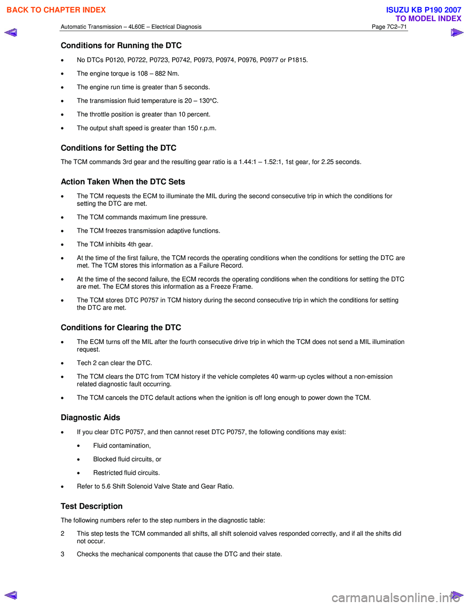
Conditions for Running the DTC
• No DTCs P0120, P0722, P0723, P0742, P0973, P0974, P0976, P0977 or P1815.
• The engine torque is 108 – 882 Nm.
• The engine run time is greater than 5 seconds.
• The transmission fluid temperature is 20 – 130°C.
• The throttle position is greater than 10 percent.
• The output shaft speed is greater than 150 r.p.m.
Conditions for Setting the DTC
The TCM commands 3rd gear and the resulting gear ratio is a 1.44:1 – 1.52:1, 1st gear, for 2.25 seconds.
Action Taken When the DTC Sets
• The TCM requests the ECM to illuminate the MIL during the second consecutive trip in which the conditions for
setting the DTC are met.
• The TCM commands maximum line pressure.
• The TCM freezes transmission adaptive functions.
• The TCM inhibits 4th gear.
• At the time of the first failure, the TCM records the operating conditions when the conditions for setting the DTC are
met. The TCM stores this information as a Failure Record.
• At the time of the second failure, the ECM records the operating conditions when the conditions for setting the DTC
are met. The ECM stores this information as a Freeze Frame.
• The TCM stores DTC P0757 in TCM history during the second consecutive trip in which the conditions for setting
the DTC are met.
Conditions for Clearing the DTC
• The ECM turns off the MIL after the fourth consecutive drive trip in which the TCM does not send a MIL illumination
request.
• Tech 2 can clear the DTC.
• The TCM clears the DTC from TCM history if the vehicle completes 40 warm-up cycles without a non-emission
related diagnostic fault occurring.
• The TCM cancels the DTC default actions when the ignition is off long enough to power down the TCM.
Diagnostic Aids
• If you clear DTC P0757, and then cannot reset DTC P0757, the following conditions may exist:
• Fluid contamination,
• Blocked fluid circuits, or
• Restricted fluid circuits.
• Refer to 5.6 Shift Solenoid Valve State and Gear Ratio.
Test Description
The following numbers refer to the step numbers in the diagnostic table:
2 This step tests the TCM commanded all shifts, all shift solenoid valves responded correctly, and if all the shifts did not occur.
3 Checks the mechanical components that cause the DTC and their state.
BACK TO CHAPTER INDEX
TO MODEL INDEX
ISUZU KB P190 2007
Page 3871 of 6020
Automatic Transmission – 4L60E – Electrical Diagnosis Page 7C2–85
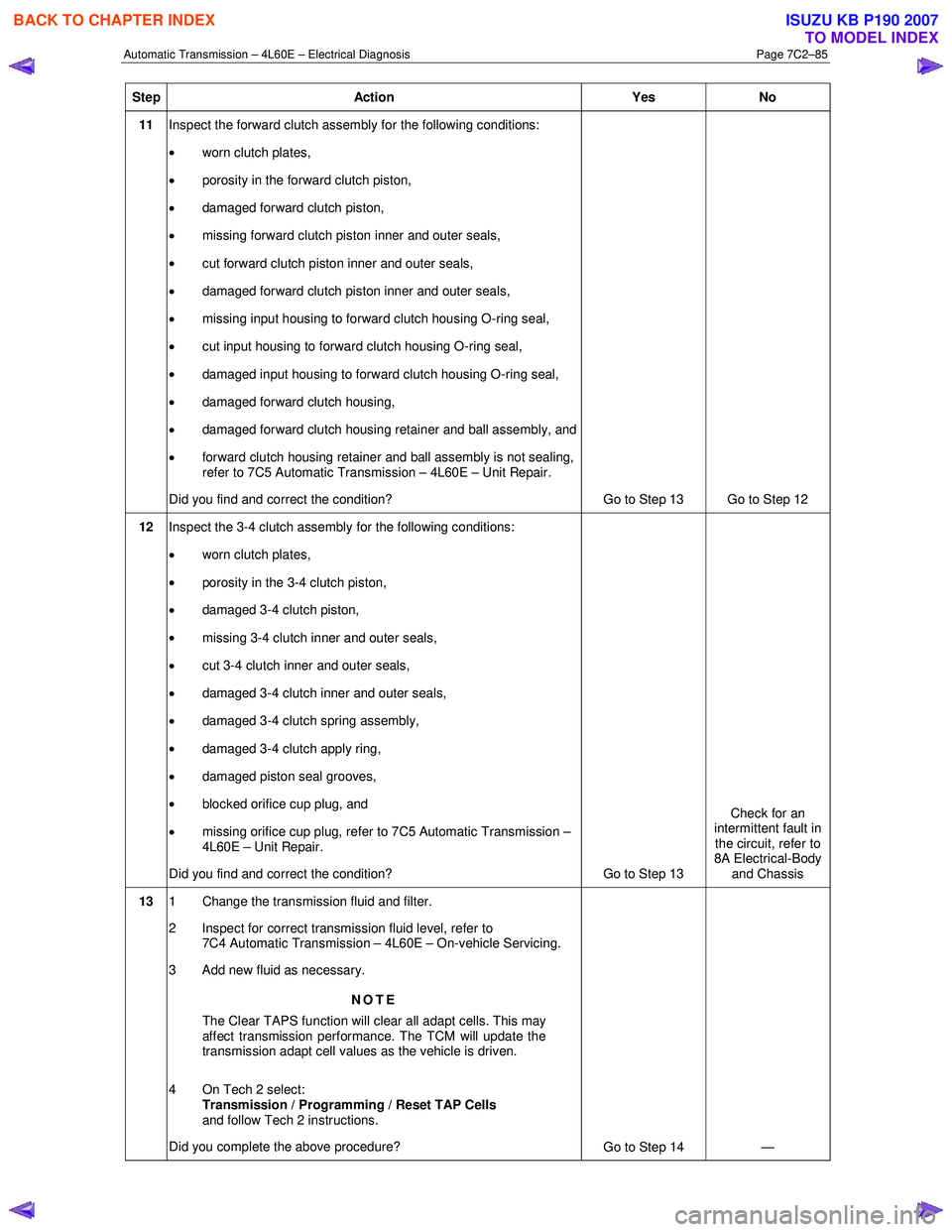
Step Action Yes No
11 Inspect the forward clutch assembly for the following conditions:
• worn clutch plates,
• porosity in the forward clutch piston,
• damaged forward clutch piston,
• missing forward clutch piston inner and outer seals,
• cut forward clutch piston inner and outer seals,
• damaged forward clutch piston inner and outer seals,
• missing input housing to forward clutch housing O-ring seal,
• cut input housing to forward clutch housing O-ring seal,
• damaged input housing to forward clutch housing O-ring seal,
• damaged forward clutch housing,
• damaged forward clutch housing retainer and ball assembly, and
• forward clutch housing retainer and ball assembly is not sealing,
refer to 7C5 Automatic Transmission – 4L60E – Unit Repair.
Did you find and correct the condition? Go to Step 13 Go to Step 12
12 Inspect the 3-4 clutch assembly for the following conditions:
• worn clutch plates,
• porosity in the 3-4 clutch piston,
• damaged 3-4 clutch piston,
• missing 3-4 clutch inner and outer seals,
• cut 3-4 clutch inner and outer seals,
• damaged 3-4 clutch inner and outer seals,
• damaged 3-4 clutch spring assembly,
• damaged 3-4 clutch apply ring,
• damaged piston seal grooves,
• blocked orifice cup plug, and
• missing orifice cup plug, refer to 7C5 Automatic Transmission –
4L60E – Unit Repair.
Did you find and correct the condition? Go to Step 13 Check for an
intermittent fault in the circuit, refer to
8A Electrical-Body and Chassis
13 1 Change the transmission fluid and filter.
2 Inspect for correct transmission fluid level, refer to 7C4 Automatic Transmission – 4L60E – On-vehicle Servicing.
3 Add new fluid as necessary.
NOTE
The Clear TAPS function will clear all adapt cells. This may
affect transmission performance. The TCM will update the
transmission adapt cell values as the vehicle is driven.
4 On Tech 2 select: Transmission / Programming / Reset TAP Cells
and follow Tech 2 instructions.
Did you complete the above procedure? Go to Step 14 —
BACK TO CHAPTER INDEX
TO MODEL INDEX
ISUZU KB P190 2007
Page 4266 of 6020
CONSTRUCTION AND FUNCTION 7A1-27
Item Description
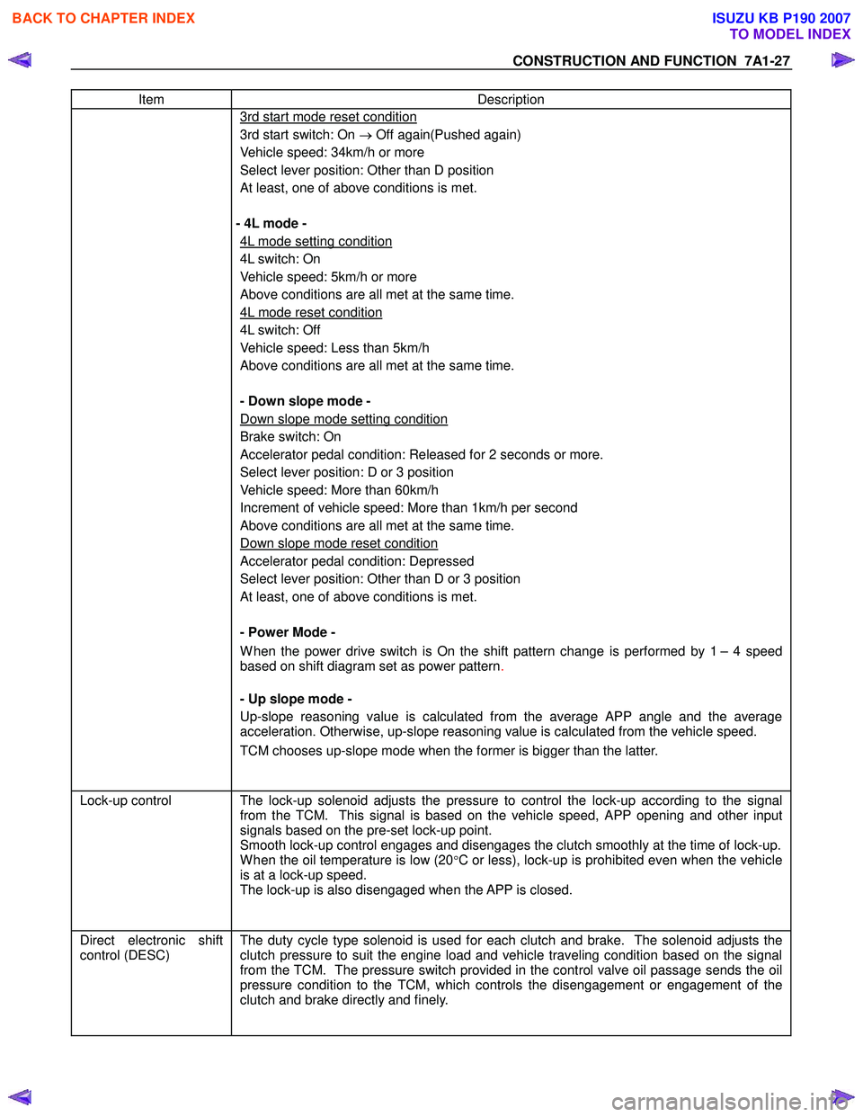
3rd start mode reset condition
3rd start switch: On → Off again(Pushed again)
Vehicle speed: 34km/h or more
Select lever position: Other than D position
At least, one of above conditions is met.
- 4L mode -
4L mode setting condition
4L switch: On
Vehicle speed: 5km/h or more
Above conditions are all met at the same time.
4L mode reset condition
4L switch: Off
Vehicle speed: Less than 5km/h
Above conditions are all met at the same time.
- Down slope mode -
Down slope mode setting condition
Brake switch: On
Accelerator pedal condition: Released for 2 seconds or more.
Select lever position: D or 3 position
Vehicle speed: More than 60km/h
Increment of vehicle speed: More than 1km/h per second
Above conditions are all met at the same time.
Down slope mode reset condition
Accelerator pedal condition: Depressed
Select lever position: Other than D or 3 position
At least, one of above conditions is met.
- Power Mode -
W hen the power drive switch is On the shift pattern change is performed by 1 – 4 speed
based on shift diagram set as power pattern .
- Up slope mode -
Up-slope reasoning value is calculated from the average APP angle and the average
acceleration. Otherwise, up-slope reasoning value is calculated from the vehicle speed.
TCM chooses up-slope mode when the former is bigger than the latter.
Lock-up control The lock-up solenoid adjusts the pressure to control the lock-up according to the signal
from the TCM. This signal is based on the vehicle speed, APP opening and other input
signals based on the pre-set lock-up point.
Smooth lock-up control engages and disengages the clutch smoothly at the time of lock-up.
W hen the oil temperature is low (20°C or less), lock-up is prohibited even when the vehicle
is at a lock-up speed.
The lock-up is also disengaged when the APP is closed.
Direct electronic shift
control (DESC)
The duty cycle type solenoid is used for each clutch and brake. The solenoid adjusts the
clutch pressure to suit the engine load and vehicle traveling condition based on the signal
from the TCM. The pressure switch provided in the control valve oil passage sends the oil
pressure condition to the TCM, which controls the disengagement or engagement of the
clutch and brake directly and finely.
BACK TO CHAPTER INDEX
TO MODEL INDEX
ISUZU KB P190 2007
Page 4272 of 6020
CONSTRUCTION AND FUNCTION 7A1-33
LEARNING FUNCTION
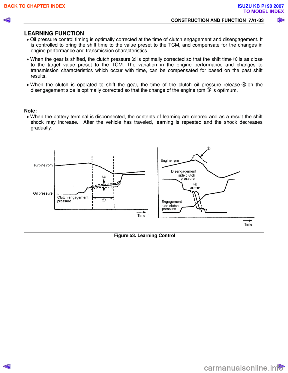
• Oil pressure control timing is optimally corrected at the time of clutch engagement and disengagement. It
is controlled to bring the shift time to the value preset to the TCM, and compensate for the changes in
engine performance and transmission characteristics.
• When the gear is shifted, the clutch pressure 2 is optimally corrected so that the shift time 1 is as close
to the target value preset to the TCM. The variation in the engine performance and changes to
transmission characteristics which occur with time, can be compensated for based on the past shift
results.
• When the clutch is operated to shift the gear, the time of the clutch oil pressure release 4 on the
disengagement side is optimally corrected so that the change of the engine rpm
3 is optimum.
Note:
• When the battery terminal is disconnected, the contents of learning are cleared and as a result the shift
shock may increase. After the vehicle has traveled, learning is repeated and the shock decreases
gradually.
Figure 53. Learning Control
BACK TO CHAPTER INDEX
TO MODEL INDEX
ISUZU KB P190 2007
Page 4444 of 6020
7A2-160 TRANSMISSION CONTROL SYSTEM (JR405E)
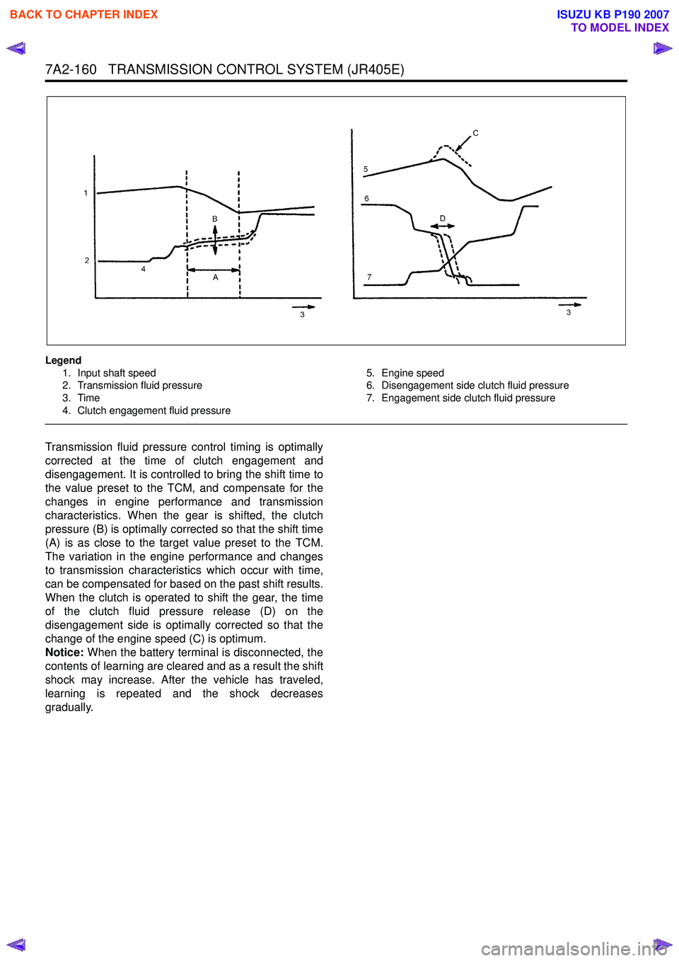
Legend1. Input shaft speed
2. Transmission fluid pressure
3. Time
4. Clutch engagement fluid pressure 5. Engine speed
6. Disengagement side clutch fluid pressure
7. Engagement side clutch fluid pressure
Transmission fluid pressure control timing is optimally
corrected at the time of clutch engagement and
disengagement. It is controlled to bring the shift time to
the value preset to the TCM, and compensate for the
changes in engine performance and transmission
characteristics. When the gear is shifted, the clutch
pressure (B) is optimally corrected so that the shift time
(A) is as close to the target value preset to the TCM.
The variation in the engine performance and changes
to transmission characteristics which occur with time,
can be compensated for based on the past shift results.
When the clutch is operated to shift the gear, the time
of the clutch fluid pressure release (D) on the
disengagement side is optimally corrected so that the
change of the engine speed (C) is optimum.
Notice: When the battery terminal is disconnected, the
contents of learning are cleared and as a result the shift
shock may increase. After the vehicle has traveled,
learning is repeated and the shock decreases
gradually.
BACK TO CHAPTER INDEX
TO MODEL INDEX
ISUZU KB P190 2007
Page 4925 of 6020
TRANSFER CONTROL SYSTEM 7D1-51
Trouble diagnosis based on the operation switch, transfer indicator lamp and operating
sound “Check 4WD” indicator ON (operation guard based on the transfer actuator
position detection error)
This condition indicates a faulty circuit related with the detection (limit) switches of the system actuator.
Detection (limit) switches detect the actuator operating angle based on their combinations.
The controller monitors transition of the actuator based on the combination of the detection (limit) switch output.
If the transition based on the combinations indicates some trouble, it is memorized, and shifting operation is
stopped when the trouble is counted 5 times, and the “Check 4W D” indicator lights up. At this time, the system
permits operation to 2H only.
W hen such a condition occurs, inspection of the transfer shift actuator, checking of the harness related with the
detection (limit) switch, and erasure of the memory of the controller is required.
(Refer to the memory erasure procedure for the erasure of the memory.)
At this time, the position indicator may flash at 4Hz. It means that a detection (limit) switch trouble wad detected
in the operation process shown by that position indicator (example: 4W D indicator when shifting from 2H to 4H).
Caution:
During trouble diagnosis and correction, do not turn ON the ignition with the harness connector of the
transfer actuator disconnected. (Do not disconnect the harness connector of the transfer actuator when
the ignition is ON.)
If the controller is connected during this condition, a limit SW trouble is judged and the above-described
“Check 4WD” condition occurs.
This can be reset by clearing the memory.
When disconnecting the harness connector of the actuator and turning the ignition ON is required, remove
the controller at the same time or remove the IG power fuse of the transfer controller.
BACK TO CHAPTER INDEX
TO MODEL INDEX
ISUZU KB P190 2007