Page 2587 of 6020
Engine Mechanical – V6 Page 6A1–108
Primary Timing Chain Tensioner
Figure 6A1 – 133
1 Inspect the primary timing chain tensioner for worn shoe surface (1), refer to Figure 6A1 – 133.
2 Inspect the tensioner for a locked or binding tensioner shaft (2). Reset the plunger (3) and ensure the tensioner shaft moves freely in and out of the body of the tensioner.
NOTE
To reset the tensioner, use a suitably sized flat
blade screwdriver or Tool No. J 45027 (4) to wind
the plunger in a clockwise direction, into the
tensioner shaft.
3 Replace a damaged tensioner as required.
Left-hand Secondary Timing Chain Guide
1 Inspect the left-hand secondary timing chain guide for the following:
• worn guide surface (1),
• cracked or broken guide surface (2), and
• cracked or damaged guide base (3).
2 Replace a damaged guide as required.
Figure 6A1 – 134
BACK TO CHAPTER INDEX
TO MODEL INDEX
ISUZU KB P190 2007
Page 2589 of 6020

Engine Mechanical – V6 Page 6A1–110
2 Inspect the tensioner for locked or binding tensioner shaft (2). Reset the plunger (3) and ensure the tensioner shaft
moves freely in and out of the body of the tensioner.
NOTE
To reset the tensioner, use a suitably sized flat
blade screwdriver or Tool No. J 45027 (4) to wind
the plunger in a clockwise direction, into the
tensioner shaft.
3 Replace a damaged tensioner as required.
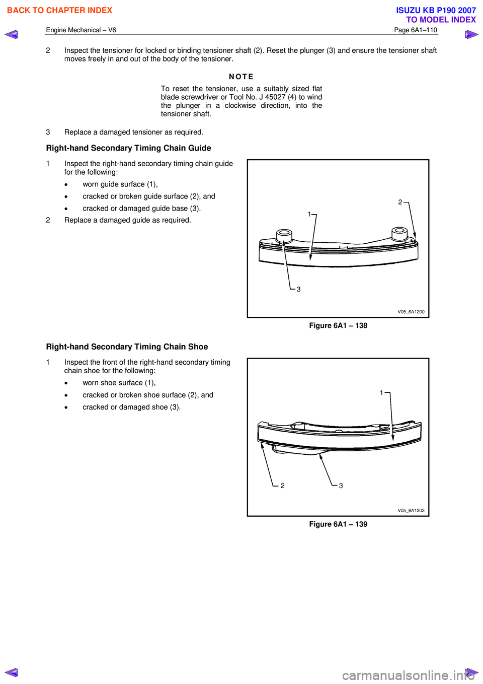
Right-hand Secondary Timing Chain Guide
1 Inspect the right-hand secondary timing chain guide for the following:
• worn guide surface (1),
• cracked or broken guide surface (2), and
• cracked or damaged guide base (3).
2 Replace a damaged guide as required.
Figure 6A1 – 138
Right-hand Secondary Timing Chain Shoe
1 Inspect the front of the right-hand secondary timing chain shoe for the following:
• worn shoe surface (1),
• cracked or broken shoe surface (2), and
• cracked or damaged shoe (3).
Figure 6A1 – 139
BACK TO CHAPTER INDEX
TO MODEL INDEX
ISUZU KB P190 2007
Page 2590 of 6020
Engine Mechanical – V6 Page 6A1–111
2 Inspect the back of the shoe for a damaged, worn or
missing timing chain tensioner contact pad (1).
Replace a damaged shoe as required.
Figure 6A1 – 140
Right-hand Secondary Timing Chain Tensioner
Figure 6A1 – 141
1 Inspect the right-hand secondary timing chain tensioner for damaged plunger-to-shoe contact surface (1), refer to Figure 6A1 – 141.
NOTE
To reset the tensioner, use a suitably sized flat
blade screwdriver or Tool No. J 45027 (4) to wind
the plunger in a clockwise direction, into the
tensioner shaft.
2 Inspect the tensioner for a locked or binding tensioner shaft (2). Reset the plunger (3) and ensure the tensioner shaft moves freely in and out of the body of the tensioner.
3 Replace a damaged tensioner as required.
Reinstall
Left-hand Secondary Timing Chain Components
BACK TO CHAPTER INDEX
TO MODEL INDEX
ISUZU KB P190 2007
Page 2597 of 6020
Engine Mechanical – V6 Page 6A1–118
21 Install the left-hand secondary timing chain shoe
bolt (1) and tighten to the correct torque specification.
NOTE
Ensure secondary timing chain shoe is clear of
the left-hand secondary timing chain tensioner
mounting pad, before tightening the attaching
bolt.
Secondary timing chain shoe attaching
bolt torque specification ..........................20.0 – 26.0 Nm
Figure 6A1 – 158
22 Ensure the left-hand secondary timing chain tensioner is selected and orientated correctly.
Figure 6A1 – 159
23 Reset the left-hand secondary timing chain tensioner.
NOTE
To reset the tensioner, use a suitably sized flat
blade screwdriver (1) or Tool No. J 45027 (4) to
wind the plunger in a clockwise direction, into
the tensioner shaft (2).
Figure 6A1 – 160
BACK TO CHAPTER INDEX
TO MODEL INDEX
ISUZU KB P190 2007
Page 2604 of 6020
Engine Mechanical – V6 Page 6A1–125
13 Install the primary timing chain upper guide (1).
14 Install the primary timing chain upper guide bolts (2) and tighten to the correct torque specification.
Primary timing chain upper guide
attaching bolt torque specification ...........20.0 – 26.0 Nm
Figure 6A1 – 179
15 Ensure that the primary timing chain tensioner is being installed.
Figure 6A1 – 180
16 Reset the primary timing chain tensioner.
NOTE
To reset the tensioner, use a suitably sized flat
blade screwdriver (1) or Tool No. J 45027 (4) to
wind the plunger in a clockwise direction, into
the tensioner shaft (2).
Figure 6A1 – 181
BACK TO CHAPTER INDEX
TO MODEL INDEX
ISUZU KB P190 2007
Page 2612 of 6020
Engine Mechanical – V6 Page 6A1–133
15 Install the secondary timing chain shoe bolt (1) and
tighten to the correct torque specification.
Secondary timing chain shoe
attaching bolt torque specification ...........20.0 – 26.0 Nm
Figure 6A1 – 202
16 Ensure the right-hand secondary timing chain tensioner is selected and orientated correctly.
Figure 6A1 – 203
17 Reset the right-hand secondary timing chain tensioner.
NOTE
To reset the tensioner, use a suitably sized flat
blade screwdriver (1) or Tool No. J 45027 to
wind the plunger in a clockwise direction, into
the tensioner shaft (2).
Figure 6A1 – 204
BACK TO CHAPTER INDEX
TO MODEL INDEX
ISUZU KB P190 2007
Page 2620 of 6020

Engine Mechanical – V6 Page 6A1–141
Reassemble
CAUTION
As there are no serviceable components
within the oil pump, a disassembled oil pump
must be replaced.
Reinstall
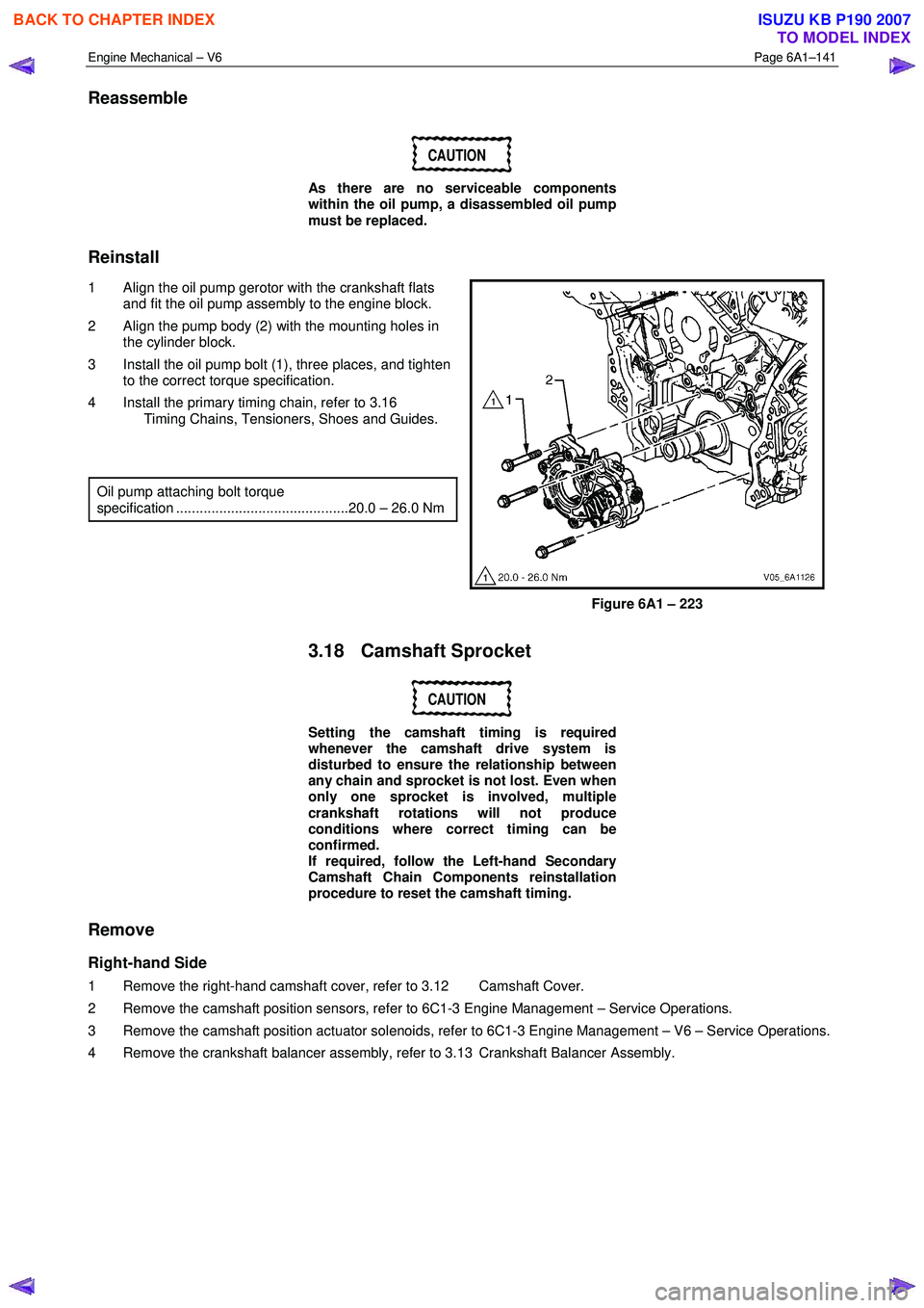
1 Align the oil pump gerotor with the crankshaft flats and fit the oil pump assembly to the engine block.
2 Align the pump body (2) with the mounting holes in the cylinder block.
3 Install the oil pump bolt (1), three places, and tighten to the correct torque specification.
4 Install the primary timing chain, refer to 3.16 Timing Chains, Tensioners, Shoes and Guides.
Oil pump attaching bolt torque
specification ............................................20.0 – 26.0 Nm
Figure 6A1 – 223
3.18 Camshaft Sprocket
CAUTION
Setting the camshaft timing is required
whenever the camshaft drive system is
disturbed to ensure the relationship between
any chain and sprocket is not lost. Even when
only one sprocket is involved, multiple
crankshaft rotations will not produce
conditions where correct timing can be
confirmed.
If required, follow the Left-hand Secondary
Camshaft Chain Components reinstallation
procedure to reset the camshaft timing.
Remove
Right-hand Side
1 Remove the right-hand camshaft cover, refer to 3.12 Camshaft Cover.
2 Remove the camshaft position sensors, refer to 6C1-3 Engine Management – Service Operations.
3 Remove the camshaft position actuator solenoids, refer to 6C1-3 Engine Management – V6 – Service Operations.
4 Remove the crankshaft balancer assembly, refer to 3.13 Crankshaft Balancer Assembly.
BACK TO CHAPTER INDEX
TO MODEL INDEX
ISUZU KB P190 2007
Page 2777 of 6020
Engine Mechanical – V6 Page 6A1–298
Tool Number Illustration Description
J-45027
Tensioner Tool
Used to reset the timing chain tensioner plunger.
J-6125-1B
Slide Hammer
Used in conjunction with J-41818 to remove the main bearing
caps from the cylinder block during engine disassembly.
J-8062
Valve Spring Compressor
Used in conjunction with EN-46119 to remove valve springs
with the engine disassembled.
J-8087
Cylinder Bore Gauge
Commercial equivalent also available
BACK TO CHAPTER INDEX
TO MODEL INDEX
ISUZU KB P190 2007