2007 ISUZU KB P190 reset
[x] Cancel search: resetPage 2219 of 6020

ENGINE DRIVEABILITY AND EMISSIONS 6E–49
Throttle Position Sensor (TPS)
The TPS is a potentiometer connected to throttle shaft
on the throttle body.
The engine control module (ECM) monitors the voltage
on the signal line and calculates throttle position. As the
throttle valve angle is changed when accelerator pedal
moved. The TPS signal also changed at a moved
throttle valve. As the throttle valve opens, the output
increases so that the output voltage should be high.
The throttle body has a throttle plate to control the
amount of the air delivered to the engine.
Engine coolant is directed through a coolant cavity in
the throttle body to warm the throttle valve and to
prevent icing.
Idle Air Control (IAC) Valve
The idle air control valve (IAC) valve is two directional
and gives 2-way control. With power supply to the coils
controlled steps by the engine control module (ECM),
the IAC valve's pintle is moved to adjust idle speed,
raising it for fast idle when cold or there is extra load
from the air conditioning or power steering.
By moving the pintle in (to decrease air flow) or out (to
increase air flow), a controlled amount of the air can
move around the throttle plate. If the engine speed is
too low, the engine control module (ECM) will retract the
IAC pintle, resulting in more air moving past the throttle
plate to increase the engine speed.
If the engine speed is too high, the engine control
module (ECM) will extend the IAC pintle, allowing less
air to move past the throttle plate, decreasing the
engine speed.
The IAC pintle valve moves in small step called counts.
During idle, the proper position of the IAC pintle is
calculated by the engine control module (ECM) based
on battery voltage, coolant temperature, engine load,
and engine speed.
If the engine speed drops below a specified value, and
the throttle plate is closed, the engine control module
(ECM) senses a near-stall condition. The engine control
module (ECM) will then calculate a new IAC pintle valve
position to prevent stalls.
If the IAC valve is disconnected and reconnected with
the engine running, the idle speed will be wrong. In this
case, the IAC must be reset. The IAC resets when the
key is cycled “On” then “Off”. When servicing the IAC, it
should only be disconnected or connected with the
ignition “Off”.
The position of the IAC pintle valve affects engine start-
up and the idle characteristic of the vehicle.
If the IAC pintle is fully open, too much air will be
allowed into the manifold. This results in high idle
speed, along with possible hard starting and lean air/
fuel ratio.
(1) Throttle Position Sensor
(2) Idle Air Control (IAC) Valve
1
2
C harac teris t ic of TPS -R ef erenc e-
0
0.5
1
1.5 2
2.5
3
3.5 4
4.5 5
0 10 2030 405060 7080 90100 Throt t le Angle (% ) (Tec h2 R eading)
Output Voltage (V)
StepCoilAB CDCoil A H igh
(ECM J1-28) On On
Coil A Low
(ECM J1-30) On On
Coil B H igh
(ECM J1-13) On On
Coil B Low
(ECM J1-29) On On
(IAC Valve Close Direction)
(IAC Valve Open Direction)
BACK TO CHAPTER INDEX
TO MODEL INDEX
ISUZU KB P190 2007
Page 2241 of 6020
ENGINE DRIVEABILITY AND EMISSIONS 6E–71
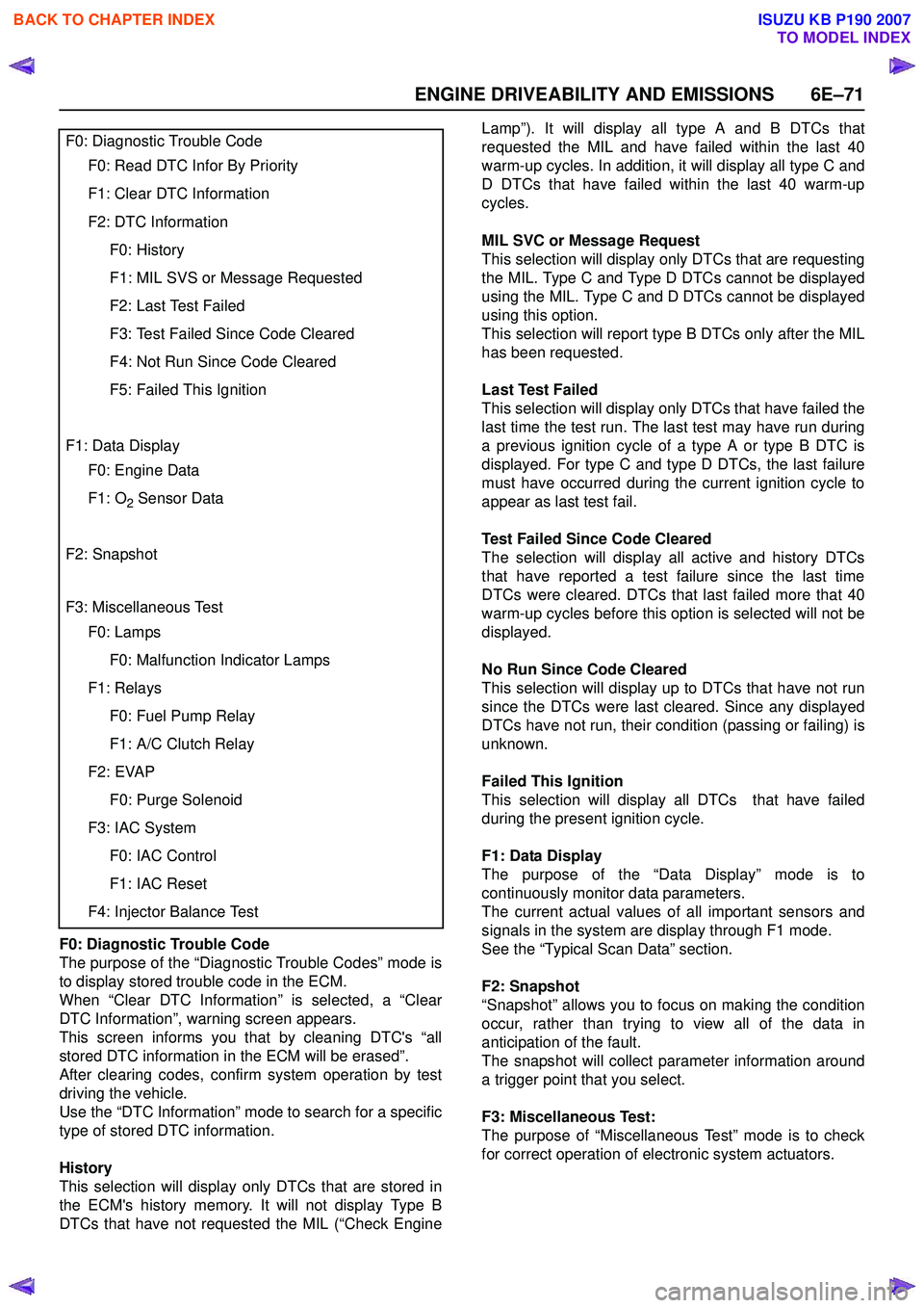
F0: Diagnostic Trouble Code
The purpose of the “Diagnostic Trouble Codes” mode is
to display stored trouble code in the ECM.
When “Clear DTC Information” is selected, a “Clear
DTC Information”, warning screen appears.
This screen informs you that by cleaning DTC's “all
stored DTC information in the ECM will be erased”.
After clearing codes, confirm system operation by test
driving the vehicle.
Use the “DTC Information” mode to search for a specific
type of stored DTC information.
History
This selection will display only DTCs that are stored in
the ECM's history memory. It will not display Type B
DTCs that have not requested the MIL (“Check Engine Lamp”). It will display all type A and B DTCs that
requested the MIL and have failed within the last 40
warm-up cycles. In addition, it will display all type C and
D DTCs that have failed within the last 40 warm-up
cycles.
MIL SVC or Message Request
This selection will display only DTCs that are requesting
the MIL. Type C and Type D DTCs cannot be displayed
using the MIL. Type C and D DTCs cannot be displayed
using this option.
This selection will report type B DTCs only after the MIL
has been requested.
Last Test Failed
This selection will display only DTCs that have failed the
last time the test run. The last test may have run during
a previous ignition cycle of a type A or type B DTC is
displayed. For type C and type D DTCs, the last failure
must have occurred during the current ignition cycle to
appear as last test fail.
Test Failed Since Code Cleared
The selection will display all active and history DTCs
that have reported a test failure since the last time
DTCs were cleared. DTCs that last failed more that 40
warm-up cycles before this option is selected will not be
displayed.
No Run Since Code Cleared
This selection will display up to DTCs that have not run
since the DTCs were last cleared. Since any displayed
DTCs have not run, their condition (passing or failing) is
unknown.
Failed This Ignition
This selection will display all DTCs that have failed
during the present ignition cycle.
F1: Data Display
The purpose of the “Data Display” mode is to
continuously monitor data parameters.
The current actual values of all important sensors and
signals in the system are display through F1 mode.
See the “Typical Scan Data” section.
F2: Snapshot
“Snapshot” allows you to focus on making the condition
occur, rather than trying to view all of the data in
anticipation of the fault.
The snapshot will collect parameter information around
a trigger point that you select.
F3: Miscellaneous Test:
The purpose of “Miscellaneous Test” mode is to check
for correct operation of electronic system actuators.
F0: Diagnostic Trouble Code
F0: Read DTC Infor By Priority
F1: Clear DTC Information
F2: DTC Information
F0: History
F1: MIL SVS or Message Requested
F2: Last Test Failed
F3: Test Failed Since Code Cleared
F4: Not Run Since Code Cleared
F5: Failed This Ignition
F1: Data Display
F0: Engine Data
F1: O2 Sensor Data
F2: Snapshot
F3: Miscellaneous Test
F0: Lamps
F0: Malfunction Indicator Lamps
F1: Relays
F0: Fuel Pump Relay
F1: A/C Clutch Relay
F2: EVAP
F0: Purge Solenoid
F3: IAC System
F0: IAC Control
F1: IAC Reset
F4: Injector Balance Test
BACK TO CHAPTER INDEX
TO MODEL INDEX
ISUZU KB P190 2007
Page 2243 of 6020
ENGINE DRIVEABILITY AND EMISSIONS 6E–73
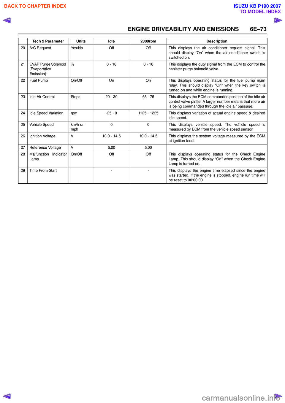
20 A/C Request Yes/NoOffOff This displays the air conditioner request signal. Thisshould display “On” when the air conditioner switch is
switched on.
21 EVAP Purge Solenoid (Evaporative
Emission) %0 - 100 - 10 This displays the duty signal from the ECM to control the
canister purge solenoid valve.
22 Fuel Pump On/OffOnOn This displays operating status for the fuel pump main
relay. This should display “On” when the key switch is
turned on and while engine is running.
23 Idle Air Control Steps20 - 3065 - 75 This displays the ECM commanded position of the idle air control valve pintle. A larger number means that more air
is being commanded through the idle air passage.
24 Idle Speed Variation rpm-25 - 01125 - 1225 This displays variation of actual engine speed & desired idle speed.
25 Vehicle Speed km/h or mph00This displays vehicle speed. The vehicle speed is
measured by ECM from the vehicle speed sensor.
26 Ignition Voltage V10.0 - 14.510.0 - 14.5 This displays the system voltage measured by the ECM at ignition feed.
27 Reference Voltage V5.005.00
28 Malfunction Indicator
Lamp On/OffOffOff This displays operating status for the Check Engine
Lamp. This should display “On” when the Check Engine
Lamp is turned on.
29Time From Start--This displays the engine time elapsed since the engine
was started. If the engine is stopped, engine run time will
be reset to 00:00:00
Tech 2 ParameterUnitsIdle2000rpmDescription
BACK TO CHAPTER INDEX
TO MODEL INDEX
ISUZU KB P190 2007
Page 2245 of 6020
ENGINE DRIVEABILITY AND EMISSIONS 6E–75
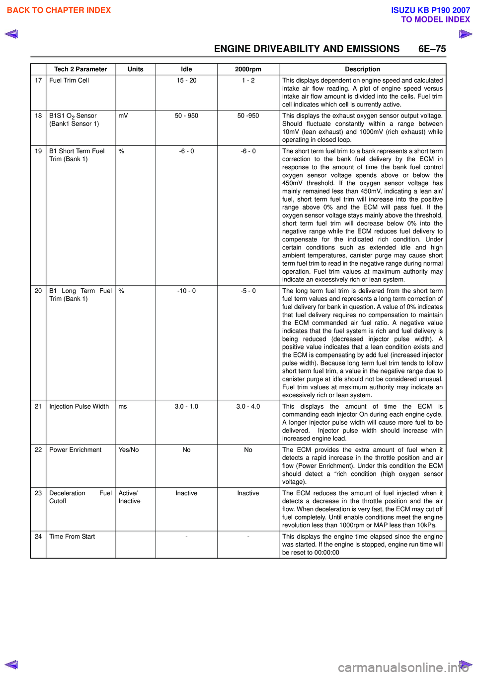
17 Fuel Trim Cell15 - 201 - 2 This displays dependent on engine speed and calculatedintake air flow reading. A plot of engine speed versus
intake air flow amount is divided into the cells. Fuel trim
cell indicates which cell is currently active.
18B1S1 O2 Sensor
(Bank1 Sensor 1)mV50 - 95050 -950 This displays the exhaust oxygen sensor output voltage. Should fluctuate constantly within a range between
10mV (lean exhaust) and 1000mV (rich exhaust) while
operating in closed loop.
19B1 Short Term Fuel
Trim (Bank 1)%-6 - 0-6 - 0 The short term fuel trim to a bank represents a short term correction to the bank fuel delivery by the ECM in
response to the amount of time the bank fuel control
oxygen sensor voltage spends above or below the
450mV threshold. If the oxygen sensor voltage has
mainly remained less than 450mV, indicating a lean air/
fuel, short term fuel trim will increase into the positive
range above 0% and the ECM will pass fuel. If the
oxygen sensor voltage stays mainly above the threshold,
short term fuel trim will decrease below 0% into the
negative range while the ECM reduces fuel delivery to
compensate for the indicated rich condition. Under
certain conditions such as extended idle and high
ambient temperatures, canister purge may cause short
term fuel trim to read in the negative range during normal
operation. Fuel trim values at maximum authority may
indicate an excessively rich or lean system.
20B1 Long Term Fuel
Trim (Bank 1)%-10 - 0-5 - 0 The long term fuel trim is delivered from the short term fuel term values and represents a long term correction of
fuel delivery for bank in question. A value of 0% indicates
that fuel delivery requires no compensation to maintain
the ECM commanded air fuel ratio. A negative value
indicates that the fuel system is rich and fuel delivery is
being reduced (decreased injector pulse width). A
positive value indicates that a lean condition exists and
the ECM is compensating by add fuel (increased injector
pulse width). Because long term fuel trim tends to follow
short term fuel trim, a value in the negative range due to
canister purge at idle should not be considered unusual.
Fuel trim values at maximum authority may indicate an
excessively rich or lean system.
21Injection Pulse Widthms3.0 - 1.03.0 - 4.0 This displays the amount of time the ECM is commanding each injector On during each engine cycle.
A longer injector pulse width will cause more fuel to be
delivered. Injector pulse width should increase with
increased engine load.
22Power EnrichmentYe s / N oNoNo The ECM provides the extra amount of fuel when it detects a rapid increase in the throttle position and air
flow (Power Enrichment). Under this condition the ECM
should detect a “rich condition (high oxygen sensor
voltage).
23Deceleration Fuel
Cutoff Active/
InactiveInactiveInactiveThe ECM reduces the amount of fuel injected when it
detects a decrease in the throttle position and the air
flow. When deceleration is very fast, the ECM may cut off
fuel completely. Until enable conditions meet the engine
revolution less than 1000rpm or MAP less than 10kPa.
24Time From Start--This displays the engine time elapsed since the engine
was started. If the engine is stopped, engine run time will
be reset to 00:00:00
Tech 2 ParameterUnitsIdle2000rpmDescription
BACK TO CHAPTER INDEX
TO MODEL INDEX
ISUZU KB P190 2007
Page 2246 of 6020
6E–76 ENGINE DRIVEABILITY AND EMISSIONS
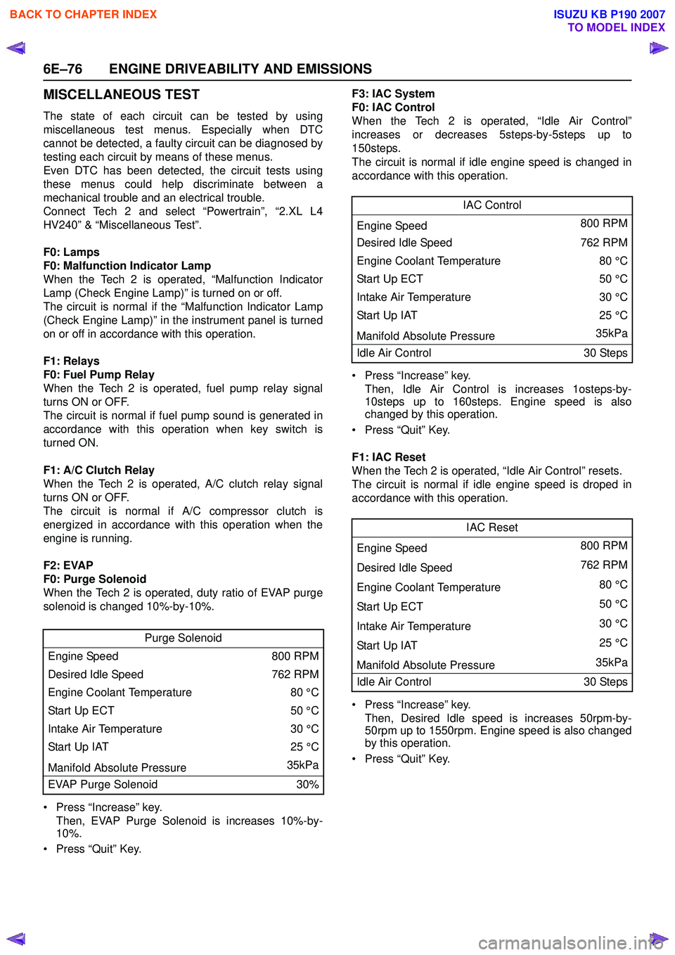
MISCELLANEOUS TEST
The state of each circuit can be tested by using
miscellaneous test menus. Especially when DTC
cannot be detected, a faulty circuit can be diagnosed by
testing each circuit by means of these menus.
Even DTC has been detected, the circuit tests using
these menus could help discriminate between a
mechanical trouble and an electrical trouble.
Connect Tech 2 and select “Powertrain”, “2.XL L4
HV240” & “Miscellaneous Test”.
F0: Lamps
F0: Malfunction Indicator Lamp
When the Tech 2 is operated, “Malfunction Indicator
Lamp (Check Engine Lamp)” is turned on or off.
The circuit is normal if the “Malfunction Indicator Lamp
(Check Engine Lamp)” in the instrument panel is turned
on or off in accordance with this operation.
F1: Relays
F0: Fuel Pump Relay
When the Tech 2 is operated, fuel pump relay signal
turns ON or OFF.
The circuit is normal if fuel pump sound is generated in
accordance with this operation when key switch is
turned ON.
F1: A/C Clutch Relay
When the Tech 2 is operated, A/C clutch relay signal
turns ON or OFF.
The circuit is normal if A/C compressor clutch is
energized in accordance with this operation when the
engine is running.
F2: EVAP
F0: Purge Solenoid
When the Tech 2 is operated, duty ratio of EVAP purge
solenoid is changed 10%-by-10%.
• Press “Increase” key. Then, EVAP Purge Solenoid is increases 10%-by-
10%.
• Press “Quit” Key. F3: IAC System
F0: IAC Control
When the Tech 2 is operated, “Idle Air Control”
increases or decreases 5steps-by-5steps up to
150steps.
The circuit is normal if idle engine speed is changed in
accordance with this operation.
• Press “Increase” key. Then, Idle Air Control is increases 1osteps-by-
10steps up to 160steps. Engine speed is also
changed by this operation.
• Press “Quit” Key.
F1: IAC Reset
When the Tech 2 is operated, “Idle Air Control” resets.
The circuit is normal if idle engine speed is droped in
accordance with this operation.
• Press “Increase” key. Then, Desired Idle speed is increases 50rpm-by-
50rpm up to 1550rpm. Engine speed is also changed
by this operation.
• Press “Quit” Key.
Purge Solenoid
Engine Speed 800 RPM
Desired Idle Speed 762 RPM
Engine Coolant Temperature 80 °C
Start Up ECT 50 °C
Intake Air Temperature 30 °C
Start Up IAT 25 °C
Manifold Absolute Pressure 35kPa
EVAP Purge Solenoid 30%
IAC Control
Engine Speed 800 RPM
Desired Idle Speed 762 RPM
Engine Coolant Temperature 80 °C
Sta rt U p E C T 50 °C
Intake Air Temperature 30 °C
Start Up IAT25 °C
Manifold Absolute Pressure 35kPa
Idle Air Control 30 Steps
IAC Reset
Engine Speed 800 RPM
Desired Idle Speed 762 RPM
Engine Coolant Temperature 80 °C
Sta rt U p E C T 50 °C
Intake Air Temperature 30 °C
Start Up IAT 25 °C
Manifold Absolute Pressure 35kPa
Idle Air Control 30 Steps
BACK TO CHAPTER INDEX
TO MODEL INDEX
ISUZU KB P190 2007
Page 2288 of 6020
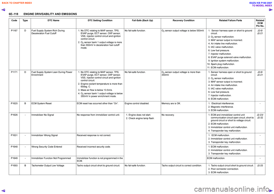
6E–118 ENGINE DRIVEABILITY AND EMISSIONSP1167 D Fuel Supply System Rich During
Deceleration Fuel Cutoff 1. No DTC relating to MAP sensor, TPS,
EVAP purge, ECT sensor, CKP sensor,
VSS, injector control circuit and ignition
control circuit.
2. O
2 sensor bank 1 output voltage is more
than 550mV in deceleration fuel cutoff
mode. No fail-safe function.
O
2 sensor output voltage is below 550mV. 1. Sensor harness open or short to ground
circuit.
2. O
2 sensor malfunction.
3. MAF sensor output is incorrect.
4. Air intake line malfunction.
5. IAC valve malfunction.
6. Low fuel pressure.
7. Injector malfunction.
8. EVAP purge solenoid valve malfunction.
9. Ignition system malfunction.
10. Spark plug malfunction. 11. ECM malfunction. J2-6/
J2-21
P1171 D Fuel Supply System Lean During Power Enrichment 1. No DTC relating to MAP sensor, TPS,
EVAP purge, ECT sensor, CKP sensor,
VSS, injector control circuit and ignition
control circuit.
2. Engine coolant temperature is more than 60deg. C.
3. Mass air flow is below 13.5m/s.
4. O
2 sensor bank 1 output voltage is below
350mV in power enrichment mode. No fail-safe function.
O
2 sensor output voltage is more than
350mV. 1. Sensor harness open or short to ground
circuit.
2. O
2 sensor malfunction.
3. MAF sensor output is incorrect.
4. Air intake line malfunction.
5. IAC valve malfunction.
6. Low fuel pressure.
7. Injector malfunction.
8. ECM malfunction. J2-6/
J2-21
P1625 B ECM System Reset ECM reset has occurred other than “On ”. Engine control disabled. Memory are is OK. 1. Electrical interference.
2. Magnetic interference.
3. ECM malfunction. -
P1626 - Immobilizer No Signal No response from immobilizer control unit. 1. Engine does not start.
2. Check engine lamp flash.No recovery.
1. ECM and immobilizer control unit
communication circuit open circuit, short to
ground circuit or short to voltage circuit.
2. ECM malfunction.
3. Immobilizer control unit malfunction.
4. Transponder key malfunction. J2-23/
J2-32
P1631 - Immobilizer Wrong Signal Received response is not correct. 1. ECM malfunction.
2. Immobilizer control unit malfunction.
3. Transponder key malfunction. -
P1648 - Wrong Security Code Entered Received incorrect security code. 1. ECM malfunction.
2. Immobilizer control unit malfunction.
3. Transponder key malfunction. -
P1649 - Immobilizer Function Not Programmed Immobilizer function is not programmed in the ECM. ECM malfunction.
-
P1693 B Tachometer Output Low Voltage Tacho output circuit short to ground circuit. No fail-safe function. Tacho output circuit is correct condition. 1. Tacho output circuit short to ground circuit.
2. Poor connector connection.
3. ECM malfunction. J2-25
Code Type
DTC Name DTC Setting Condition Fail-Safe (Back Up)Recovery Condition Related Failure PartsRelated
ECM
Pin No.
BACK TO CHAPTER INDEX
TO MODEL INDEX
ISUZU KB P190 2007
Page 2387 of 6020
ENGINE DRIVEABILITY AND EMISSIONS 6E–217
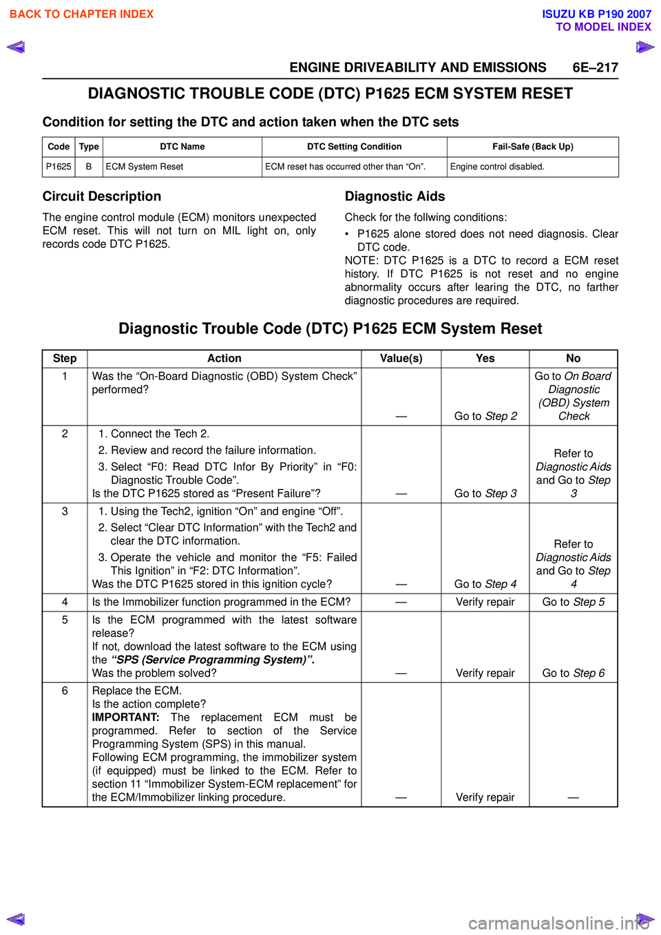
DIAGNOSTIC TROUBLE CODE (DTC) P1625 ECM SYSTEM RESET
Condition for setting the DTC and action taken when the DTC sets
Circuit Description
The engine control module (ECM) monitors unexpected
ECM reset. This will not turn on MIL light on, only
records code DTC P1625.
Diagnostic Aids
Check for the follwing conditions:
• P1625 alone stored does not need diagnosis. Clear DTC code.
NOTE: DTC P1625 is a DTC to record a ECM reset
history. If DTC P1625 is not reset and no engine
abnormality occurs after learing the DTC, no farther
diagnostic procedures are required.
Diagnostic Trouble Code (DTC) P1625 ECM System Reset
Code Type DTC Name DTC Setting Condition Fail-Safe (Back Up)
P1625 B ECM System Reset ECM reset has occurred other than “On”. Engine control disabled.
StepAction Value(s) Yes No
1 Was the “On-Board Diagnostic (OBD) System Check” performed?
—Go to Step 2Go to
On Board
Diagnostic
(OBD) System Check
2 1. Connect the Tech 2. 2. Review and record the failure information.
3. Select “F0: Read DTC Infor By Priority” in “F0: Diagnostic Trouble Code”.
Is the DTC P1625 stored as “Present Failure”? — Go to Step 3Refer to
Diagnostic Aids and Go to Step
3
3 1. Using the Tech2, ignition “On” and engine “Off”. 2. Select “Clear DTC Information” with the Tech2 andclear the DTC information.
3. Operate the vehicle and monitor the “F5: Failed This Ignition” in “F2: DTC Information”.
Was the DTC P1625 stored in this ignition cycle? — Go to Step 4Refer to
Diagnostic Aids and Go to Step
4
4 Is the Immobilizer function programmed in the ECM? — Verify repair Go to Step 5
5 Is the ECM programmed with the latest software release?
If not, download the latest software to the ECM using
the “SPS (Service Programming System)”.
Was the problem solved? — Verify repair Go to Step 6
6 Replace the ECM. Is the action complete?
IMPORTANT: The replacement ECM must be
programmed. Refer to section of the Service
Programming System (SPS) in this manual.
Following ECM programming, the immobilizer system
(if equipped) must be linked to the ECM. Refer to
section 11 “Immobilizer System-ECM replacement” for
the ECM/Immobilizer linking procedure. — Verify repair —
BACK TO CHAPTER INDEX
TO MODEL INDEX
ISUZU KB P190 2007
Page 2573 of 6020
Engine Mechanical – V6 Page 6A1–94
3.16 Timing Chains, Tensioners, Shoes and
Guides
CAUTION
Setting the camshaft timing is required
whenever the camshaft drive system has
been disturbed and the relationship between
any chain and sprocket has been lost. If
required, follow the left-hand secondary
timing chain reinstallation procedure to reset
the camshaft timing.
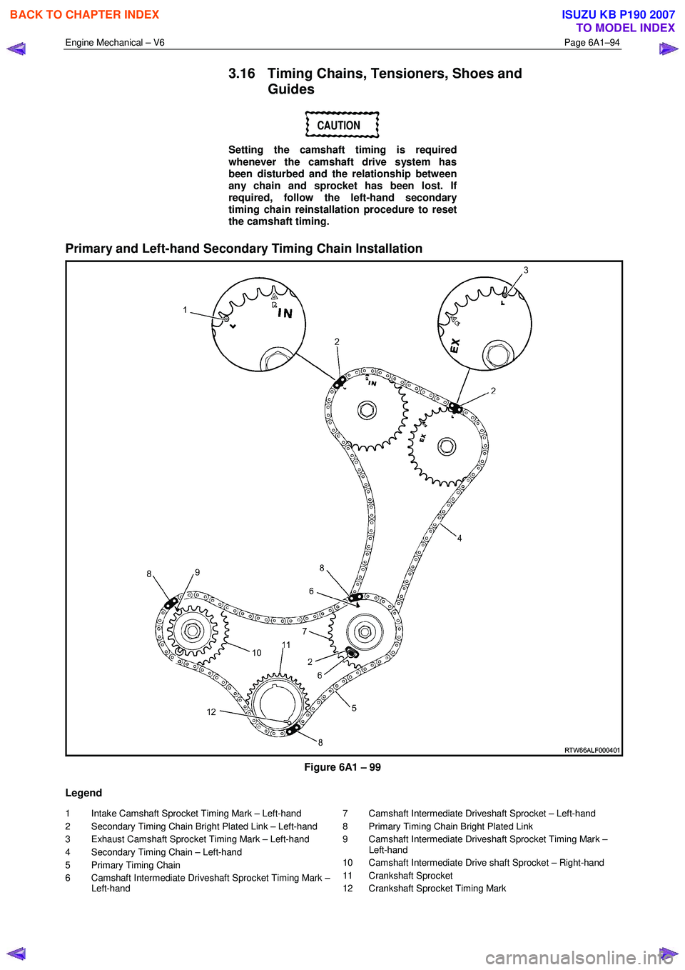
Primary and Left-hand Secondary Timing Chain Installation
Figure 6A1 – 99
Legend
1 Intake Camshaft Sprocket Timing Mark – Left-hand
2 Secondary Timing Chain Bright Plated Link – Left-hand
3 Exhaust Camshaft Sprocket Timing Mark – Left-hand
4 Secondary Timing Chain – Left-hand
5 Primary Timing Chain
6 Camshaft Intermediate Driveshaft Sprocket Timing Mark – Left-hand 7 Camshaft Intermediate Driveshaft Sprocket – Left-hand
8 Primary Timing Chain Bright Plated Link
9 Camshaft Intermediate Driveshaft Sprocket Timing Mark – Left-hand
10 Camshaft Intermediate Drive shaft Sprocket – Right-hand
11 Crankshaft Sprocket
12 Crankshaft Sprocket Timing Mark
BACK TO CHAPTER INDEX
TO MODEL INDEX
ISUZU KB P190 2007