2007 ISUZU KB P190 parking brake
[x] Cancel search: parking brakePage 4103 of 6020
7A3-18 ON-VEHICLE SERVICE (AW30–40LE)
Transmission Fluid Level and Condition
Inspection
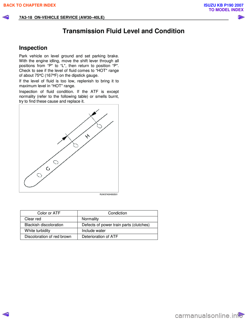
Park vehicle on level ground and set parking brake.
W ith the engine idling, move the shift lever through all
positions from “P" to “L", then return to position “P".
Check to see if the level of fluid comes to “HOT" range
of about 75 °
°°
°
C (167 °
°°
°
F) on the dipstick gauge.
If the level of fluid is too low, replenish to bring it to
maximum level in “HOT" range.
Inspection of fluid condition. If the ATF is except
normality (refer to the following table) or smells burnt,
try to find these cause and replace it.
RUW 37ASH002501
Color or ATF Condiction
Clear red Normality
Blackish discoloration Defects of power train parts (clutches)
W hite turbidity Include water
Discoloration of red brown Deterioration of ATF
BACK TO CHAPTER INDEX
TO MODEL INDEX
ISUZU KB P190 2007
Page 4240 of 6020
CONSTRUCTION AND FUNCTION 7A1-1
SECTION 7A1
CONSTRUCTION AND FUNCTION (JR405E)
TABLE OF CONTENTS
PAGE
Description ................................................................................................................... ...7A1- 3
Construction ...............................................................................................................7A1 - 3
Main Data and Specification .....................................................................................7A1- 4
Number Plate Location ..............................................................................................7A1- 5
Electronic Control Components Location ...............................................................7A1- 6
Transmission Control Module (TCM) Peripheral Circuit .........................................7A1- 7
Structure and Function of Component .........................................................................7A1- 8
Torque Converter (with Lock-up Function) .............................................................7A1- 8
Oil Pump .....................................................................................................................7 A1- 9
Input Shaft ..................................................................................................................7 A1- 10
Output Shaft ...............................................................................................................7A1 - 10
Gear Shifting Mechanism ..........................................................................................7A1- 10
Control Valve ..............................................................................................................7A1 - 14
Oil Passage .................................................................................................................7A 1- 19
Parking Function ........................................................................................................7A1- 2 0
Inhibitor Switch ..........................................................................................................7A1- 21
Turbine Sensor ...........................................................................................................7A1- 22
Speed Sensor .............................................................................................................7A1- 22
Accelerator Pedal Position Sensor ..........................................................................7A1- 23
Engine Speed Sensor (=CKP Sensor) ......................................................................7A1- 23
Brake Switch ..............................................................................................................7A1- 24
Mode Select Switch ...................................................................................................7A1- 24
Transmission Control Module (TCM) .......................................................................7A1- 25
Control Mechanism ........................................................................................................7A1- 26
Content of Function and Control ..............................................................................7A1- 26
Control Item, Input and Output .................................................................................7A1- 29
Line Pressure Control ................................................................................................7A1- 30
Lock-up Control .........................................................................................................7A1- 3 0
Direct Electric Shift Control (DESC) .........................................................................7A1- 31
BACK TO CHAPTER INDEX
TO MODEL INDEX
ISUZU KB P190 2007
Page 4242 of 6020
CONSTRUCTION AND FUNCTION 7A1-3
DESCRIPTION
CONSTRUCTION
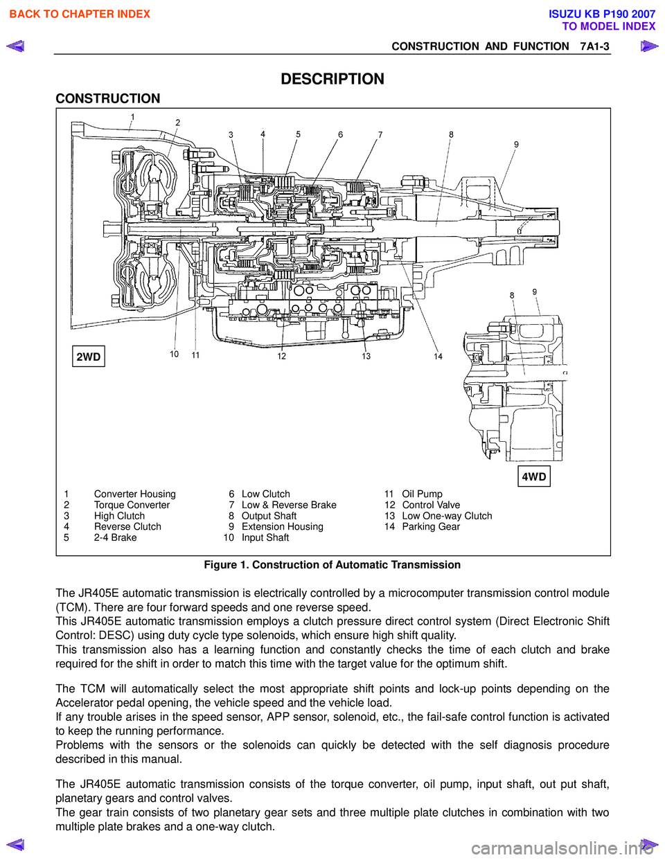
1 Converter Housing 6 Low Clutch 11 Oil Pump
2 Torque Converter 7 Low & Reverse Brake 12 Control Valve
3 High Clutch 8 Output Shaft 13 Low One-way Clutch
4 Reverse Clutch 9 Extension Housing 14 Parking Gear
5 2-4 Brake 10 Input Shaft
Figure 1. Construction of Automatic Transmission
The JR405E automatic transmission is electrically controlled by a microcomputer transmission control module
(TCM). There are four forward speeds and one reverse speed.
This JR405E automatic transmission employs a clutch pressure direct control system (Direct Electronic Shift
Control: DESC) using duty cycle type solenoids, which ensure high shift quality.
This transmission also has a learning function and constantly checks the time of each clutch and brake
required for the shift in order to match this time with the target value for the optimum shift.
The TCM will automatically select the most appropriate shift points and lock-up points depending on the
Accelerator pedal opening, the vehicle speed and the vehicle load.
If any trouble arises in the speed sensor, APP sensor, solenoid, etc., the fail-safe control function is activated
to keep the running performance.
Problems with the sensors or the solenoids can quickly be detected with the self diagnosis procedure
described in this manual.
The JR405E automatic transmission consists of the torque converter, oil pump, input shaft, out put shaft,
planetary gears and control valves.
The gear train consists of two planetary gear sets and three multiple plate clutches in combination with two
multiple plate brakes and a one-way clutch.
2WD
4WD
BACK TO CHAPTER INDEX
TO MODEL INDEX
ISUZU KB P190 2007
Page 4249 of 6020
7A1-10 CONSTRUCTION AND FUNCTION
INPUT SHAFT
• The input shaft has some oil holes, through which lubricating ATF is supplied to the torque converter, the
bearings, etc.
• The input shaft is fitted to the turbine runner in the torque converter, the reverse & high clutch drum and
the rear sun gear by means of the spline. Therefore, the engine driving force received by the torque
converter is transmitted to the reverse & high clutch drum and rear sun gear.
OUTPUT SHAFT
• The output shaft has some oil holes, through which the lubricating ATF is supplied to the bearings, the
planetary gear unit, etc.
• The output shaft transmits the engine driving force from the planetary gear to the propeller shaft.
• The front internal gear is fitted with the rear carrier assembly by spline. The parking gear is also fitted by
spline. By fixing this gear mechanically, the output shaft is fixed as required when parking the vehicle.
GEAR SHIFTING MECHANISM
• The JR405E consists of two sets of planetary gears, three multiple plate clutches, two multiple plate
brakes and a one-way clutch. They are activated in different combinations in any of four forward and one
reverse gear positions.
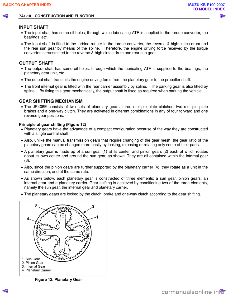
Principle of gear shifting (Figure 12) • Planetary gears have the advantage of a compact configuration because of the way they are constructed
with a single central shaft.
• Also, unlike the manual transmission gears that require changing of the gear mesh, the gear ratio of the
planetary gears can be changed more easily by locking, releasing or rotating only some of their parts.
• A planetary gear is made up of a sun gear (1) at its center, and pinion gears (2) each of which rotates
about its own center and around the sun gear, as shown. They are all contained within the internal gear
(3).
• Also, since the pinion gears are further supported by the planetary carrier (4), they rotate as a unit in the
same direction, and at the same rate.
• As shown below, each planetary gear is constructed of three elements; a sun gear, pinion gears, an
internal gear and a planetary carrier. Gear shifting is achieved by conditioning two of the three elements,
namely the sun gear, the internal gear and planetary carrier.
• The planetary gears are locked by the clutch, brake and one-way clutch according to the gear shifting.
1. Sun Gear
2. Pinion Gear
3. Internal Gear
4. Planetary Carrier
Figure 12. Planetary Gear
BACK TO CHAPTER INDEX
TO MODEL INDEX
ISUZU KB P190 2007
Page 4277 of 6020
7A1-38 CONSTRUCTION AND FUNCTION
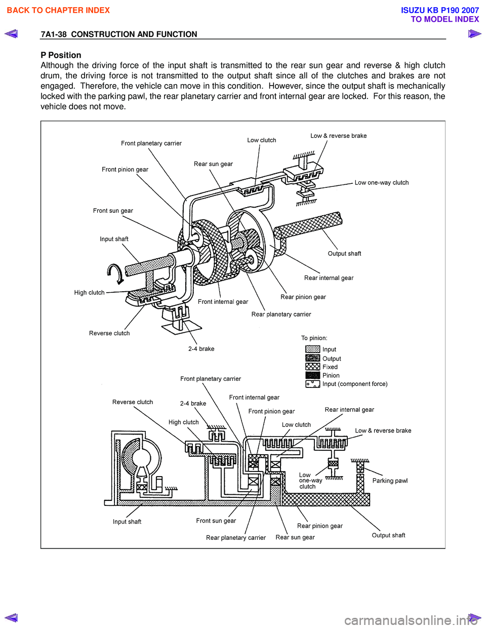
P Position
Although the driving force of the input shaft is transmitted to the rear sun gear and reverse & high clutch
drum, the driving force is not transmitted to the output shaft since all of the clutches and brakes are not
engaged. Therefore, the vehicle can move in this condition. However, since the output shaft is mechanically
locked with the parking pawl, the rear planetary carrier and front internal gear are locked. For this reason, the
vehicle does not move.
BACK TO CHAPTER INDEX
TO MODEL INDEX
ISUZU KB P190 2007
Page 4298 of 6020
7A2-14 TRANSMISSION CONTROL SYSTEM (JR405E)
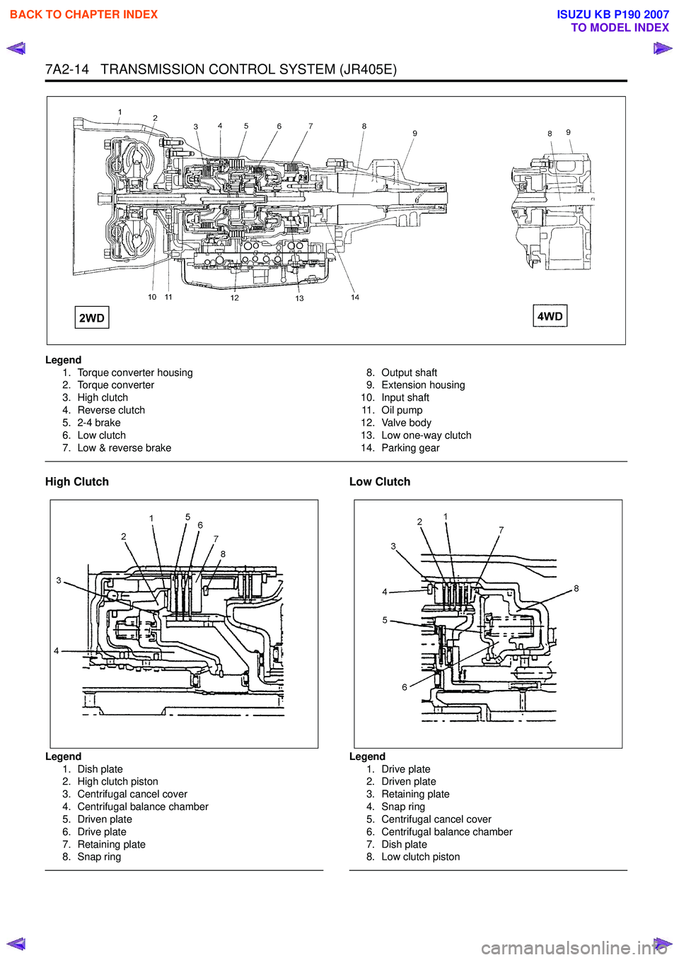
Legend1. Torque converter housing
2. Torque converter
3. High clutch
4. Reverse clutch
5. 2-4 brake
6. Low clutch
7. Low & reverse brake 8. Output shaft
9. Extension housing
10. Input shaft 11 . O i l p u m p
12. Valve body
13. Low one-way clutch
14. Parking gear
High Clutch
Legend 1. Dish plate
2. High clutch piston
3. Centrifugal cancel cover
4. Centrifugal balance chamber
5. Driven plate
6. Drive plate
7. Retaining plate
8. Snap ring
Low Clutch
Legend
1. Drive plate
2. Driven plate
3. Retaining plate
4. Snap ring
5. Centrifugal cancel cover
6. Centrifugal balance chamber
7. Dish plate
8. Low clutch piston
BACK TO CHAPTER INDEX
TO MODEL INDEX
ISUZU KB P190 2007
Page 4309 of 6020
TRANSMISSION CONTROL SYSTEM (JR405E) 7A2-25
Scan Tool Data Definitions
This information will assist in driveability problems. The
displays can be viewed while the vehicle is being
driven. Always perform the Diagnostic System Check -
Transmission Controls first. The Diagnostic System
Check will confirm proper system operation.
Accelerator Pedal Position
This parameter displays the angle of the accelerator
pedal as calculated by the engine control module
(ECM) using the signals from the accelerator pedal
position (APP) sensors. This data is sent over the pulse
wave modulation (PWM) signal from the ECM to the
TCM. The scan tool will display linearly from 0 to 100%
according to the pedal operation.
Engine Speed
This parameter displays the rotational speed of the
crankshaft as calculated by the engine control module
(ECM) based on inputs from the crankshaft position
sensor or camshaft position sensor. This data is sent
over the pulse signal from the ECM to the TCM.
AT Input Speed (Automatic Transmission)
This parameter displays the rotational speed of the
reverse & high clutch drum as calculated by the TCM
based on inputs from the input shaft speed (ISS)
sensor.
TCC Slip Speed (Torque Converter Clutch)
This parameter displays the difference between
transmission input shaft speed and the engine speed
(engine speed - input shaft speed). A negative value
indicates that the engine speed is less than the input
shaft speed, deceleration. A positive value indicates
that the engine speed is greater than the input shaft
speed, acceleration. A value of zero indicates that the
engine speed is equal to the input shaft speed, torque
converter clutch (TCC) is applied.
AT Output Speed (Automatic Transmission)
This parameter displays the rotational speed of the
parking gear that is connected to the output shaft as
calculated by the TCM based on inputs from the output
shaft speed (OSS) sensor. Vehicle Speed
This parameter indicates the vehicle speed calculated
by the TCM using the signal from the output shaft
speed sensor. The scan tool will display a low value at
lower vehicle speeds, and a high value at higher
vehicle speeds.
Current Gear
This parameter displays the current gear position
based on the command from the TCM.
Estimated Gear Ratio
This parameter displays the current gear ratio
calculated by the TCM using the signal from the input
shaft speed (ISS) sensor and the output speed sensor
(OSS) sensor.
Transmission Range (TR)
This parameter displays the selector lever position
based on the transmission range (TR) switch inputs.
TR Switch P, R, N, D, 3, 2, L (Transmission Range)
This parameter displays the input state of the
transmission range (TR) switch to the TCM. When the
selector lever is moved to each range, the scan tool
displays On.
PCS Command (Pressure Control Solenoid)
This parameter displays the commanded state of the
pressure control (PC) solenoid valve control circuit. On
indicates the solenoid valve is being energized by the
TCM, allowing line pressure to be low.
Low & Reverse Brake Solenoid Command
This parameter displays the low & reverse brake
solenoid valve control duty ratio based on the
command for the TCM. The scan tool will display a
lower percentage when the low & reverse brake is
controlled to engage (fluid pressure is applied to the
low & reverse brake hydraulic circuits). The scan tool
will display higher percentage when the low & reverse
brake is controlled to disengage (fluid pressure is
drained from the low & reverse brake hydraulic
circuits).
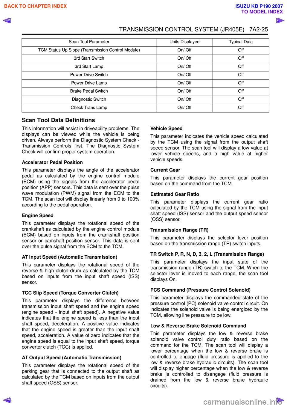
TCM Status Up Slope (Transmission Control Module) On/ OffOff
3rd Start Switch On/ OffOff
3rd Start Lamp On/ OffOff
Power Drive Switch On/ OffOff
Power Drive Lamp On/ OffOff
Brake Pedal Switch On/ OffOff
Diagnostic Switch On/ OffOff
Check Trans Lamp On/ OffOff
Scan Tool Parameter
Units DisplayedTypical Data
BACK TO CHAPTER INDEX
TO MODEL INDEX
ISUZU KB P190 2007
Page 4337 of 6020
TRANSMISSION CONTROL SYSTEM (JR405E) 7A2-53
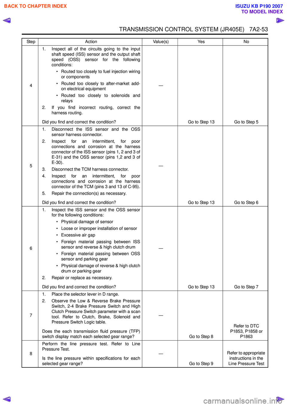
41. Inspect all of the circuits going to the input
shaft speed (ISS) sensor and the output shaft
speed (OSS) sensor for the following
conditions:
• Routed too closely to fuel injection wiring or components
• Routed too closely to after-market add- on electrical equipment
• Routed too closely to solenoids and relays
2. If you find incorrect routing, correct the harness routing.
Did you find and correct the condition? —
Go to Step 13 Go to Step 5
5 1. Disconnect the ISS sensor and the OSS
sensor harness connector.
2. Inspect for an intermittent, for poor connections and corrosion at the harness
connector of the ISS sensor (pins 1, 2 and 3 of
E-31) and the OSS sensor (pins 1,2 and 3 of
E-30).
3. Disconnect the TCM harness connector.
4. Inspect for an intermittent, for poor connections and corrosion at the harness
connector of the TCM (pins 3 and 13 of C-95).
5. Repair the connection(s) as necessary.
Did you find and correct the condition? —
Go to Step 13 Go to Step 6
6 1. Inspect the ISS sensor and the OSS sensor
for the following conditions:
• Physical damage of sensor
• Loose or improper installation of sensor
• Excessive air gap
• Foreign material passing between ISS sensor and reverse & high clutch drum
• Foreign material passing between OSS sensor and parking gear
• Physical damage of reverse & high clutch drum or parking gear
2. Repair or replace as necessary.
Did you find and correct the condition? —
Go to Step 13 Go to Step 7
7 1. Place the selector lever in D range.
2. Observe the Low & Reverse Brake Pressure Switch, 2-4 Brake Pressure Switch and High
Clutch Pressure Switch parameter with a scan
tool. Refer to Clutch, Brake, Solenoid and
Pressure Switch Logic table.
Does the each transmission fluid pressure (TFP)
switch display match each selected gear range? —
Go to Step 8 Refer to DTC
P1853, P1858 or P1863
8 Perform the line pressure test. Refer to Line
Pressure Test.
Is the line pressure within specifications for each
selected gear range? —
Go to Step 9 Refer to appropriate
instructions in the
Line Pressure Test
Step
Action Value(s)Yes No
BACK TO CHAPTER INDEX
TO MODEL INDEX
ISUZU KB P190 2007