2007 ISUZU KB P190 parking brake
[x] Cancel search: parking brakePage 1692 of 6020
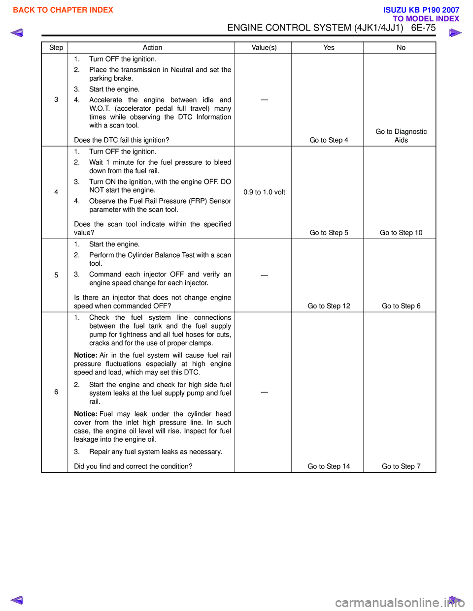
ENGINE CONTROL SYSTEM (4JK1/4JJ1) 6E-75
31. Turn OFF the ignition.
2. Place the transmission in Neutral and set the parking brake.
3. Start the engine.
4. Accelerate the engine between idle and W.O.T. (accelerator pedal full travel) many
times while observing the DTC Information
with a scan tool.
Does the DTC fail this ignition? —
Go to Step 4 Go to Diagnostic
Aids
4 1. Turn OFF the ignition.
2. Wait 1 minute for the fuel pressure to bleed down from the fuel rail.
3. Turn ON the ignition, with the engine OFF. DO NOT start the engine.
4. Observe the Fuel Rail Pressure (FRP) Sensor parameter with the scan tool.
Does the scan tool indicate within the specified
value? 0.9 to 1.0 volt
Go to Step 5 Go to Step 10
5 1. Start the engine.
2. Perform the Cylinder Balance Test with a scan tool.
3. Command each injector OFF and verify an engine speed change for each injector.
Is there an injector that does not change engine
speed when commanded OFF? —
Go to Step 12 Go to Step 6
6 1. Check the fuel system line connections
between the fuel tank and the fuel supply
pump for tightness and all fuel hoses for cuts,
cracks and for the use of proper clamps.
Notice: Air in the fuel system will cause fuel rail
pressure fluctuations especially at high engine
speed and load, which may set this DTC.
2. Start the engine and check for high side fuel system leaks at the fuel supply pump and fuel
rail.
Notice: Fuel may leak under the cylinder head
cover from the inlet high pressure line. In such
case, the engine oil level will rise. Inspect for fuel
leakage into the engine oil.
3. Repair any fuel system leaks as necessary.
Did you find and correct the condition? —
Go to Step 14 Go to Step 7
Step
Action Value(s)Yes No
BACK TO CHAPTER INDEX
TO MODEL INDEX
ISUZU KB P190 2007
Page 1697 of 6020
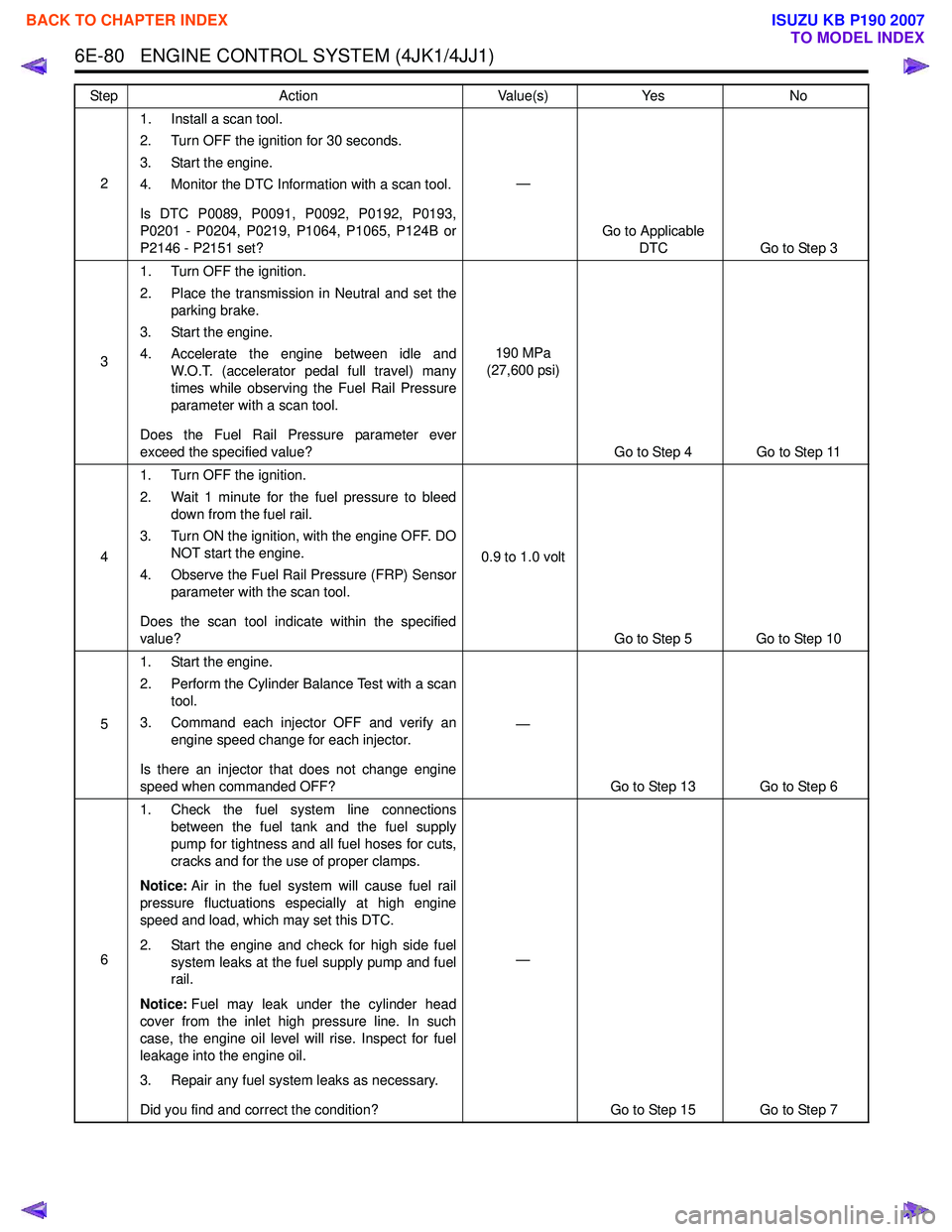
6E-80 ENGINE CONTROL SYSTEM (4JK1/4JJ1)
21. Install a scan tool.
2. Turn OFF the ignition for 30 seconds.
3. Start the engine.
4. Monitor the DTC Information with a scan tool.
Is DTC P0089, P0091, P0092, P0192, P0193,
P0201 - P0204, P0219, P1064, P1065, P124B or
P2146 - P2151 set? —
Go to Applicable DTC Go to Step 3
3 1. Turn OFF the ignition.
2. Place the transmission in Neutral and set the parking brake.
3. Start the engine.
4. Accelerate the engine between idle and W.O.T. (accelerator pedal full travel) many
times while observing the Fuel Rail Pressure
parameter with a scan tool.
Does the Fuel Rail Pressure parameter ever
exceed the specified value? 190 MPa
(27,600 psi)
Go to Step 4 Go to Step 11
4 1. Turn OFF the ignition.
2. Wait 1 minute for the fuel pressure to bleed down from the fuel rail.
3. Turn ON the ignition, with the engine OFF. DO NOT start the engine.
4. Observe the Fuel Rail Pressure (FRP) Sensor parameter with the scan tool.
Does the scan tool indicate within the specified
value? 0.9 to 1.0 volt
Go to Step 5 Go to Step 10
5 1. Start the engine.
2. Perform the Cylinder Balance Test with a scan tool.
3. Command each injector OFF and verify an engine speed change for each injector.
Is there an injector that does not change engine
speed when commanded OFF? —
Go to Step 13 Go to Step 6
6 1. Check the fuel system line connections
between the fuel tank and the fuel supply
pump for tightness and all fuel hoses for cuts,
cracks and for the use of proper clamps.
Notice: Air in the fuel system will cause fuel rail
pressure fluctuations especially at high engine
speed and load, which may set this DTC.
2. Start the engine and check for high side fuel system leaks at the fuel supply pump and fuel
rail.
Notice: Fuel may leak under the cylinder head
cover from the inlet high pressure line. In such
case, the engine oil level will rise. Inspect for fuel
leakage into the engine oil.
3. Repair any fuel system leaks as necessary.
Did you find and correct the condition? —
Go to Step 15 Go to Step 7
Step
Action Value(s)Yes No
BACK TO CHAPTER INDEX
TO MODEL INDEX
ISUZU KB P190 2007
Page 1702 of 6020
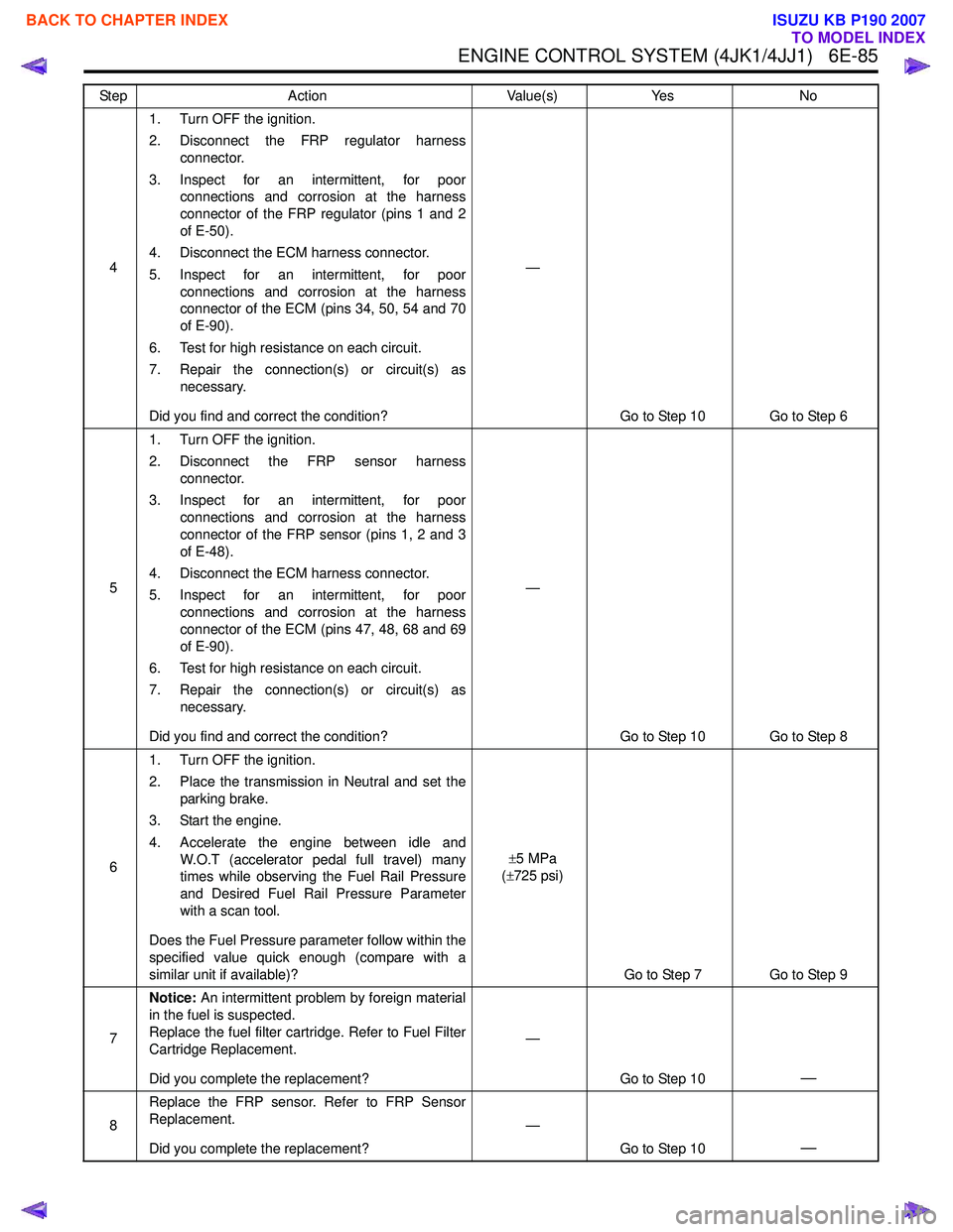
ENGINE CONTROL SYSTEM (4JK1/4JJ1) 6E-85
41. Turn OFF the ignition.
2. Disconnect the FRP regulator harness connector.
3. Inspect for an intermittent, for poor connections and corrosion at the harness
connector of the FRP regulator (pins 1 and 2
of E-50).
4. Disconnect the ECM harness connector.
5. Inspect for an intermittent, for poor connections and corrosion at the harness
connector of the ECM (pins 34, 50, 54 and 70
of E-90).
6. Test for high resistance on each circuit.
7. Repair the connection(s) or circuit(s) as necessary.
Did you find and correct the condition? —
Go to Step 10 Go to Step 6
5 1. Turn OFF the ignition.
2. Disconnect the FRP sensor harness connector.
3. Inspect for an intermittent, for poor connections and corrosion at the harness
connector of the FRP sensor (pins 1, 2 and 3
of E-48).
4. Disconnect the ECM harness connector.
5. Inspect for an intermittent, for poor connections and corrosion at the harness
connector of the ECM (pins 47, 48, 68 and 69
of E-90).
6. Test for high resistance on each circuit.
7. Repair the connection(s) or circuit(s) as necessary.
Did you find and correct the condition? —
Go to Step 10 Go to Step 8
6 1. Turn OFF the ignition.
2. Place the transmission in Neutral and set the parking brake.
3. Start the engine.
4. Accelerate the engine between idle and W.O.T (accelerator pedal full travel) many
times while observing the Fuel Rail Pressure
and Desired Fuel Rail Pressure Parameter
with a scan tool.
Does the Fuel Pressure parameter follow within the
specified value quick enough (compare with a
similar unit if available)? ±
5 MPa
( ± 725 psi)
Go to Step 7 Go to Step 9
7 Notice:
An intermittent problem by foreign material
in the fuel is suspected.
Replace the fuel filter cartridge. Refer to Fuel Filter
Cartridge Replacement.
Did you complete the replacement? —
Go to Step 10
—
8Replace the FRP sensor. Refer to FRP Sensor
Replacement.
Did you complete the replacement? —
Go to Step 10
—
Step Action Value(s)Yes No
BACK TO CHAPTER INDEX
TO MODEL INDEX
ISUZU KB P190 2007
Page 1709 of 6020
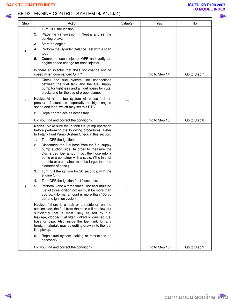
6E-92 ENGINE CONTROL SYSTEM (4JK1/4JJ1)
61. Turn OFF the ignition.
2. Place the transmission in Neutral and set the parking brake.
3. Start the engine.
4. Perform the Cylinder Balance Test with a scan tool.
5. Command each injector OFF and verify an engine speed change for each injector.
Is there an injector that does not change engine
speed when commanded OFF? —
Go to Step 14 Go to Step 7
7 1. Check the fuel system line connections
between the fuel tank and the fuel supply
pump for tightness and all fuel hoses for cuts,
cracks and for the use of proper clamps.
Notice: Air in the fuel system will cause fuel rail
pressure fluctuations especially at high engine
speed and load, which may set this DTC.
2. Repair or replace as necessary.
Did you find and correct the condition? —
Go to Step 16 Go to Step 8
8 Notice:
Make sure the in-tank fuel pump operation
before performing the following procedures. Refer
to In-tank Fuel Pump System Check in this section.
1. Turn OFF the ignition.
2. Disconnect the fuel hose from the fuel supply pump suction side. In order to measure the
discharged fuel amount, put the hose into a
bottle or a container with a scale. (The inlet of
a bottle or a container must be larger than the
diameter of hose.)
3. Turn ON the ignition for 20 seconds, with the engine OFF.
4. Turn OFF the ignition for 10 seconds.
5. Perform 3 and 4 three times. The accumulated fuel of three ignition cycles must be more than
300 cc. (Normal amount is more than 100 cc
per one ignition cycle.)
Notice: If there is a leak or a restriction on the
suction side, the fuel from the hose will not flow out
sufficiently that is most likely caused by fuel
leakage, clogged fuel filter, kinked or crushed fuel
hose or pipe. Also inside the fuel tank for any
foreign materials may be getting drawn into the fuel
line pickup.
6. Repair fuel system leaking or restrictions as necessary.
Did you find and correct the condition? —
Go to Step 16 Go to Step 9
Step
Action Value(s)Yes No
BACK TO CHAPTER INDEX
TO MODEL INDEX
ISUZU KB P190 2007
Page 1844 of 6020
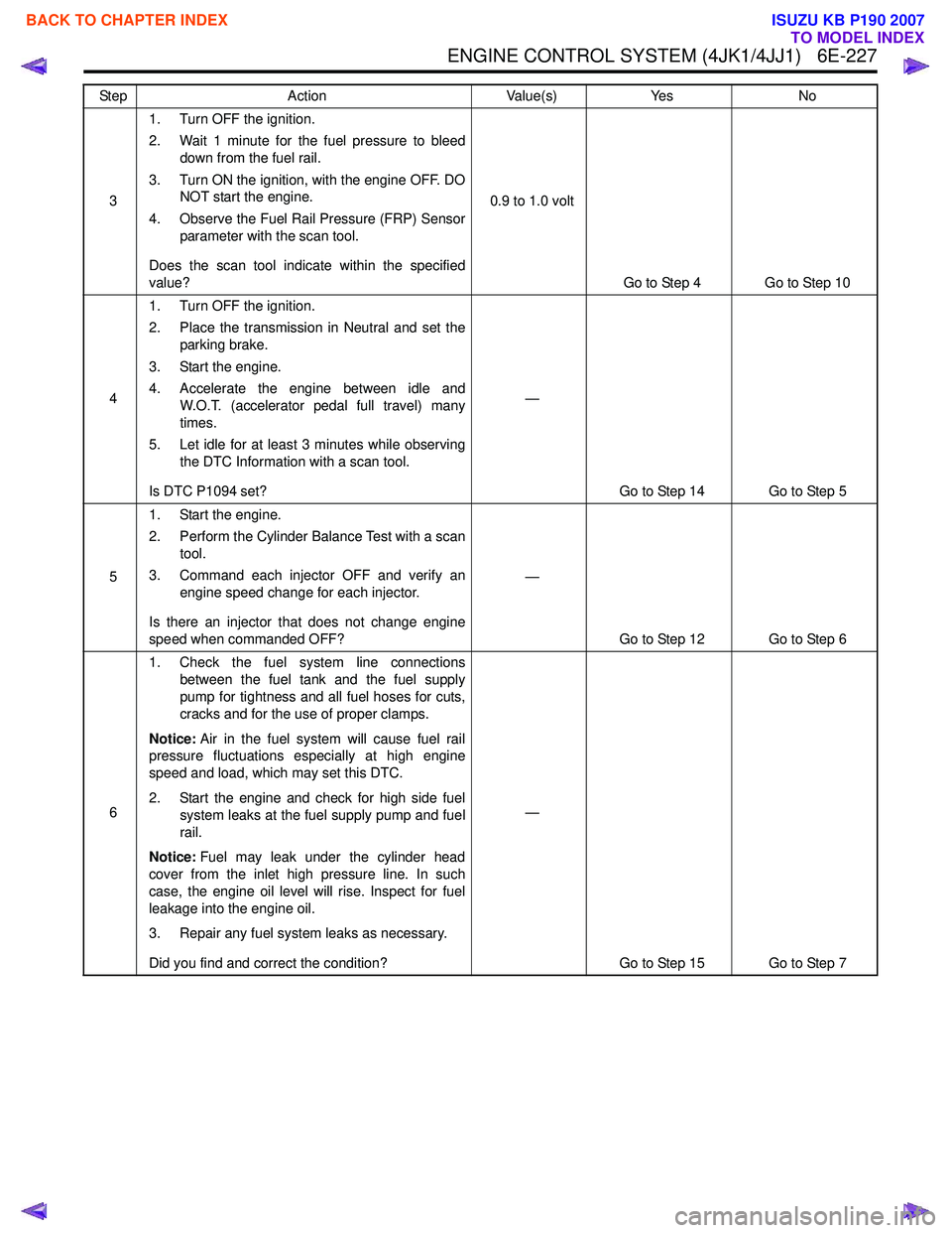
ENGINE CONTROL SYSTEM (4JK1/4JJ1) 6E-227
31. Turn OFF the ignition.
2. Wait 1 minute for the fuel pressure to bleed down from the fuel rail.
3. Turn ON the ignition, with the engine OFF. DO NOT start the engine.
4. Observe the Fuel Rail Pressure (FRP) Sensor parameter with the scan tool.
Does the scan tool indicate within the specified
value? 0.9 to 1.0 volt
Go to Step 4 Go to Step 10
4 1. Turn OFF the ignition.
2. Place the transmission in Neutral and set the parking brake.
3. Start the engine.
4. Accelerate the engine between idle and W.O.T. (accelerator pedal full travel) many
times.
5. Let idle for at least 3 minutes while observing the DTC Information with a scan tool.
Is DTC P1094 set? —
Go to Step 14 Go to Step 5
5 1. Start the engine.
2. Perform the Cylinder Balance Test with a scan tool.
3. Command each injector OFF and verify an engine speed change for each injector.
Is there an injector that does not change engine
speed when commanded OFF? —
Go to Step 12 Go to Step 6
6 1. Check the fuel system line connections
between the fuel tank and the fuel supply
pump for tightness and all fuel hoses for cuts,
cracks and for the use of proper clamps.
Notice: Air in the fuel system will cause fuel rail
pressure fluctuations especially at high engine
speed and load, which may set this DTC.
2. Start the engine and check for high side fuel system leaks at the fuel supply pump and fuel
rail.
Notice: Fuel may leak under the cylinder head
cover from the inlet high pressure line. In such
case, the engine oil level will rise. Inspect for fuel
leakage into the engine oil.
3. Repair any fuel system leaks as necessary.
Did you find and correct the condition? —
Go to Step 15 Go to Step 7
Step
Action Value(s)Yes No
BACK TO CHAPTER INDEX
TO MODEL INDEX
ISUZU KB P190 2007
Page 1850 of 6020

ENGINE CONTROL SYSTEM (4JK1/4JJ1) 6E-233
51. Turn OFF the ignition.
2. Wait 1 minute for the fuel pressure to bleed down from the fuel rail.
3. Turn ON the ignition, with the engine OFF. DO NOT start the engine.
4. Observe the Fuel Rail Pressure (FRP) Sensor parameter with the scan tool.
Does the scan tool indicate within the specified
value? 0.9 to 1.0 volt
Go to Step 6 Go to Step 13
6 1. Turn OFF the ignition.
2. Place the transmission in Neutral and set the parking brake.
3. Start the engine and let idle for at least 3 minutes while observing the DTC Information
with a scan tool.
Does the DTC fail this ignition? —
Go to Step 8 Go to Step 7
7 1. Accelerate the engine between idle and
W.O.T. (accelerator pedal full travel) many
times.
2. Let idle for at least 3 minutes while observing the DTC Information with a scan tool.
Does the DTC fail this ignition? —
Go to Step 18 Go to Step 8
8 1. Start the engine.
2. Perform the Cylinder Balance Test with a scan tool.
3. Command each injector OFF and verify an engine speed change for each injector.
Is there an injector that does not change engine
speed when commanded OFF? —
Go to Step 16 Go to Step 9
9 1. Check the fuel system line connections
between the fuel tank and the fuel supply
pump for tightness and all fuel hoses for cuts,
cracks and for the use of proper clamps.
Notice: Air in the fuel system will cause fuel rail
pressure fluctuations especially at high engine
speed and load, which may set this DTC.
2. Repair or replace as necessary.
Did you find and correct the condition? —
Go to Step 19 Go to Step 10
Step
Action Value(s)Yes No
BACK TO CHAPTER INDEX
TO MODEL INDEX
ISUZU KB P190 2007
Page 1920 of 6020
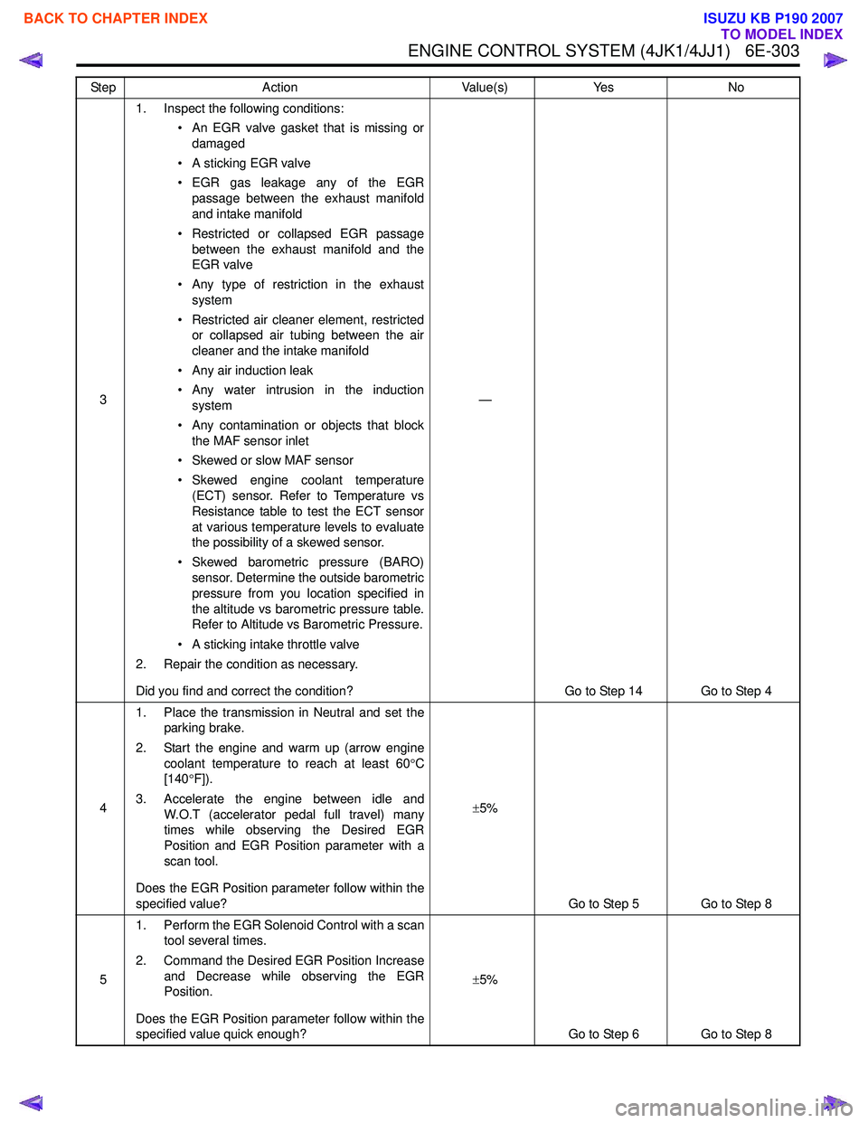
ENGINE CONTROL SYSTEM (4JK1/4JJ1) 6E-303
31. Inspect the following conditions:
• An EGR valve gasket that is missing ordamaged
• A sticking EGR valve
• EGR gas leakage any of the EGR passage between the exhaust manifold
and intake manifold
• Restricted or collapsed EGR passage between the exhaust manifold and the
EGR valve
• Any type of restriction in the exhaust system
• Restricted air cleaner element, restricted or collapsed air tubing between the air
cleaner and the intake manifold
• Any air induction leak
• Any water intrusion in the induction system
• Any contamination or objects that block the MAF sensor inlet
• Skewed or slow MAF sensor
• Skewed engine coolant temperature (ECT) sensor. Refer to Temperature vs
Resistance table to test the ECT sensor
at various temperature levels to evaluate
the possibility of a skewed sensor.
• Skewed barometric pressure (BARO) sensor. Determine the outside barometric
pressure from you location specified in
the altitude vs barometric pressure table.
Refer to Altitude vs Barometric Pressure.
• A sticking intake throttle valve
2. Repair the condition as necessary.
Did you find and correct the condition? —
Go to Step 14 Go to Step 4
4 1. Place the transmission in Neutral and set the
parking brake.
2. Start the engine and warm up (arrow engine coolant temperature to reach at least 60 °C
[140 °F]).
3. Accelerate the engine between idle and W.O.T (accelerator pedal full travel) many
times while observing the Desired EGR
Position and EGR Position parameter with a
scan tool.
Does the EGR Position parameter follow within the
specified value? ±
5%
Go to Step 5 Go to Step 8
5 1. Perform the EGR Solenoid Control with a scan
tool several times.
2. Command the Desired EGR Position Increase and Decrease while observing the EGR
Position.
Does the EGR Position parameter follow within the
specified value quick enough? ±
5%
Go to Step 6 Go to Step 8
Step
Action Value(s)Yes No
BACK TO CHAPTER INDEX
TO MODEL INDEX
ISUZU KB P190 2007
Page 1938 of 6020

ENGINE CONTROL SYSTEM (4JK1/4JJ1) 6E-321
31. Inspect the following conditions:
• Air leakage around the boost pressuresensor objects that block the sensor hole.
• Air leaking around any of the air induction tubing between the turbocharger and
intake manifold. Check for damaged
components and for loose clamps.
• Misrouted, disconnected or kinked turbocharger nozzle control actuator
vacuum hoses. Refer to Vacuum Hose
Routing Diagram in this section for
correct routing.
• Turbine shaft binding causing lower turbocharger spinning speeds. Refer to
the Turbocharger in engine mechanical
section for diagnosis.
• Turbocharger nozzle control actuator for a stuck condition or slow movement.
Refer to Turbocharger in engine
mechanical section for testing.
• Intake throttle valve sticking. Perform the Intake Throttle Solenoid Control with a
scan tool.
• Restricted air cleaner element, restricted or collapsed air tubing between the air
cleaner and the boost pressure sensor.
• Oil in the air induction tubing causing an incorrect boost pressure sensor signal.
When there is adhesion of oil inside of
tubing, intercooler or turbocharger it
needs to be wiped off.
2. Repair the condition as necessary.
Did you find and correct the condition? —
Go to Step 8 Go to Step 4
4 1. Place the transmission in Neutral and set the
parking brake.
2. Accelerate the engine between idle and W.O.T. (accelerator pedal full travel) many
times while observing the Desired Boost
Pressure and Boost Pressure parameter with
a scan tool.
3. Drive the vehicle that the engine speed is more than 2000 RPM and the Calculated
Engine Load parameter reaches at least 50%
for longer than 10 seconds (such as
acceleration on ramp) while comparing the
Boost Pressure to the Desired Boost
Pressure.
Does the Boost Pressure parameter follow within
the specified value? ±
20 kPa ( ±3
psi)
System OK Go to Step 5
Step
Action Value(s)Yes No
BACK TO CHAPTER INDEX
TO MODEL INDEX
ISUZU KB P190 2007