2007 ISUZU KB P190 parking brake
[x] Cancel search: parking brakePage 4799 of 6020
CLUTCH 7C-21
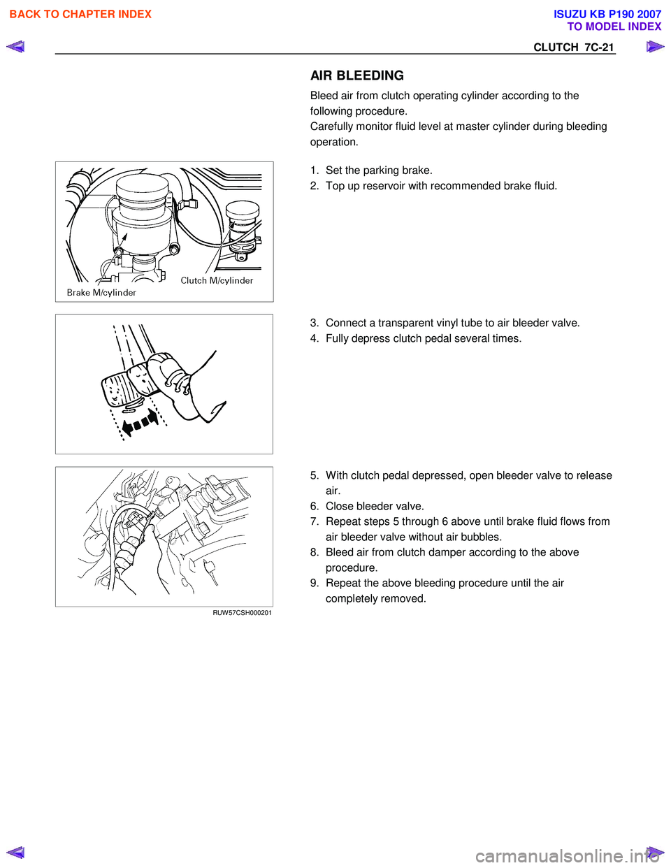
AIR BLEEDING
Bleed air from clutch operating cylinder according to the
following procedure.
Carefully monitor fluid level at master cylinder during bleeding
operation.
1. Set the parking brake.
2. Top up reservoir with recommended brake fluid.
3. Connect a transparent vinyl tube to air bleeder valve.
4. Fully depress clutch pedal several times.
RUW 57CSH000201
5. W ith clutch pedal depressed, open bleeder valve to release
air.
6. Close bleeder valve.
7. Repeat steps 5 through 6 above until brake fluid flows from air bleeder valve without air bubbles.
8. Bleed air from clutch damper according to the above procedure.
9. Repeat the above bleeding procedure until the air completely removed.
BACK TO CHAPTER INDEX
TO MODEL INDEX
ISUZU KB P190 2007
Page 4922 of 6020
7D1-48 TRANSFER CONTROL SYSTEM
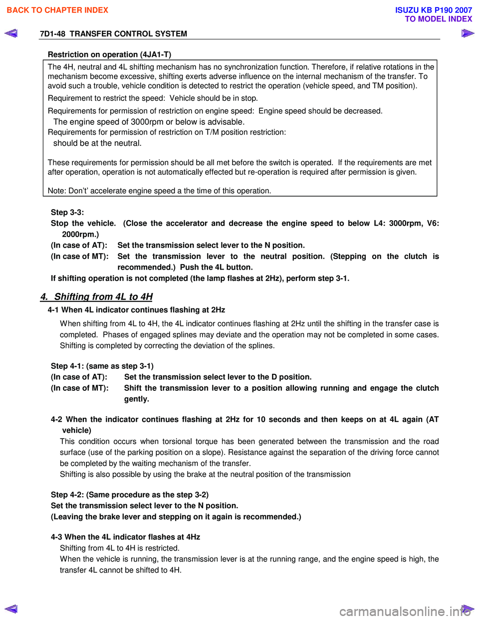
Restriction on operation (4JA1-T)
The 4H, neutral and 4L shifting mechanism has no synchronization function. Therefore, if relative rotations in the
mechanism become excessive, shifting exerts adverse influence on the internal mechanism of the transfer. To
avoid such a trouble, vehicle condition is detected to restrict the operation (vehicle speed, and TM position).
Requirement to restrict the speed: Vehicle should be in stop.
Requirements for permission of restriction on engine speed: Engine speed should be decreased.
The engine speed of 3000rpm or below is advisable.
Requirements for permission of restriction on T/M position restriction:
should be at the neutral.
These requirements for permission should be all met before the switch is operated. If the requirements are met
after operation, operation is not automatically effected but re-operation is required after permission is given.
Note: Don’t’ accelerate engine speed a the time of this operation.
Step 3-3:
Stop the vehicle. (Close the accelerator and decrease the engine speed to below L4: 3000rpm, V6: 2000rpm.)
(In case of AT): Set the transmission select lever to the N position.
(In case of MT): Set the transmission lever to the neutral position. (Stepping on the clutch is recommended.) Push the 4L button.
If shifting operation is not completed (the lamp flashes at 2Hz), perform step 3-1.
4. Shifting from 4L to 4H
4-1 When 4L indicator continues flashing at 2Hz
W hen shifting from 4L to 4H, the 4L indicator continues flashing at 2Hz until the shifting in the transfer case is
completed. Phases of engaged splines may deviate and the operation may not be completed in some cases.
Shifting is completed by correcting the deviation of the splines.
Step 4-1: (same as step 3-1)
(In case of AT): Set the transmission select lever to the D position.
(In case of MT): Shift the transmission lever to a position allowing running and engage the clutch gently.
4-2 When the indicator continues flashing at 2Hz for 10 seconds and then keeps on at 4L again (AT
vehicle)
This condition occurs when torsional torque has been generated between the transmission and the road
surface (use of the parking position on a slope). Resistance against the separation of the driving force cannot
be completed by the waiting mechanism of the transfer.
Shifting is also possible by using the brake at the neutral position of the transmission
Step 4-2: (Same procedure as the step 3-2)
Set the transmission select lever to the N position.
(Leaving the brake lever and stepping on it again is recommended.)
4-3 When the 4L indicator flashes at 4Hz
Shifting from 4L to 4H is restricted.
W hen the vehicle is running, the transmission lever is at the running range, and the engine speed is high, the
transfer 4L cannot be shifted to 4H.
BACK TO CHAPTER INDEX
TO MODEL INDEX
ISUZU KB P190 2007
Page 4958 of 6020
8A-20 ELECTRICAL-BODY AND CHASSIS
Caution:
Never push or tow the vehicle in an attempt to start it.
Extensive damage to the emission system and other
vehicle parts will result.
(Only catalytic converter vehicle)
Treat both the discharged battery and the booster battery
with great care when using jumper cables.
Carefully follow the procedure outlined below.
Always be aware of the dangers of sparking.
Failure to follow the following procedure can result in:
a. Serious personal injury, specially to your eyes.
b. Extensive property damage from a battery explosion, battery acid discharge, or electrical file.
c. Extensive damage to the electronic components o
f
both vehicles.
Do not use a 24 volt booster battery.
Serious damage to the vehicle's electrical system and
electronic components will result.
Jump Starting Procedure
1. Set the parking brake on both vehicles.
2. If one or both vehicles is equipped with a manual transmission, place the gear shift in the "NEUTRAL"
position.
3. Turn off the ignition on both vehicles.
4. Turn off all vehicle lights and accessories.
5 Be sure that the two vehicles are not touching.
Attach the end of one jumper cable to the booster battery
positive terminal.
6
Attach the other end of the same cable to the discharged
battery positive terminal.
7. Once again, check that the booster battery has a 12 volt rating.
8.
Attach one end of the remaining booster cable to the
booster battery negative terminal.
9.
Attach the other end of the booster cable to a solid ground
(such as the air conditioner compressor mounting bracket
or the alternator mounting bracket) in the engine room o
f
the vehicle with the discharged battery.
10.Be sure that the ground connection is at least 500 mm (20 in) from the discharged battery.
BACK TO CHAPTER INDEX TO MODEL INDEXISUZU KB P190 2007
Page 5289 of 6020
ELECTRICAL-BODY AND CHASSIS 8A-351
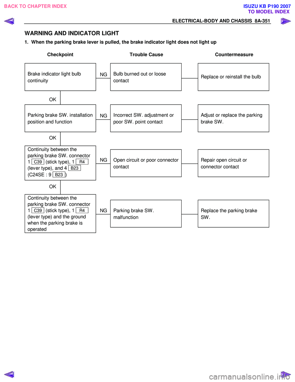
WARNING AND INDICATOR LIGHT
1. When the parking brake lever is pulled, the brake indicator light does not light up
Checkpoint Trouble Cause Countermeasure
Replace or reinstall the bulb
Bulb burned out or loose
contact
NG
Adjust or replace the parking
brake SW .
Parking brake SW . installation
position and function
Incorrect SW . adjustment or
poor SW . point contact
Continuity between the
parking brake SW . connector
1
C39 (stick type), 1 R4
(lev er type), and 4
B23
(C24SE : 9
B23 )
Repair open circuit or
connector contact
Open circuit or poor connector
contact
NG
NG
OK
OK
Brake indicator light bulb
continuity
NG
OK
Continuity between the
parking brake SW . connector
1
C39 (stick type), 1 R4
(lev er type) and the ground
when the parking brake is
operated
Replace the parking brake
SW .
Parking brake SW .
malfunction
BACK TO CHAPTER INDEX TO MODEL INDEXISUZU KB P190 2007
Page 5290 of 6020
8A-352 ELECTRICAL-BODY AND CHASSIS
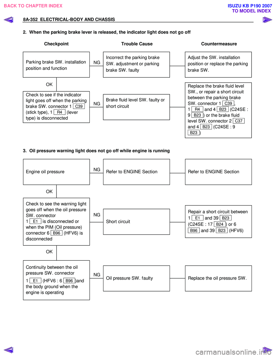
2. When the parking brake lever is released, the indicator light does not go off
Checkpoint Trouble Cause Countermeasure
Adjust the SW . installation
position or replace the parking
brake SW . Incorrect the parking brake
SW . adjustment or parking
brake SW . faulty
NG
Thermo unit malfunction
Replace the brake fluid level
SW ., or repair a short circuit
between the parking brake
SW . connector 1
C39,
1
R4 and 4 B23 (C24SE :
9
B23 ) or the brake fluid
level SW . connector 2
C37
and 4
B23 (C24SE : 9
B23 )
Check to see if the indicator
light goes off when the parking
brake SW . connector 1
C39
(stick type), 1
R4 (lever
type) is disconnected
Brake fluid level SW . faulty or
short circuit
NG
OK
Parking brake SW . installation
position and function
3. Oil pressure warning light does not go off while engine is running
Refer to ENGINE Section
Refer to ENGINE Section
NG Thermo unit malfunction
Check to see the warning light
goes off when the oil pressure
SW . connector
1
E1 is disconnected or
when the PIM (Oil pressure)
connector 6
B96 (HFV6) is
disconnected
Repair a short circuit between
1
E1 and 39 B23
(C24SE : 17
B24) or 6
B96 and 39 B23 (HFV6)
Short circuit
NG
OK
Replace the oil pressure SW .
Continuity between the oil
pressure SW . connector
1
E1 (HFV6 : 6 B96 )and
the body ground when the
engine is operating
Oil pressure SW . faulty
NG
OK
Engine oil pressure
BACK TO CHAPTER INDEX TO MODEL INDEXISUZU KB P190 2007
Page 5307 of 6020
ELECTRICAL-BODY AND CHASSIS 8A-369
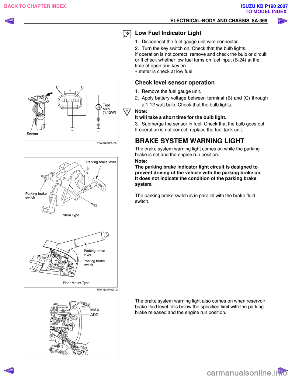
Low Fuel Indicator Light
1. Disconnect the fuel gauge unit wire connector.
2. Turn the key switch on. Check that the bulb lights.
If operation is not correct, remove and check the bulb or circuit.
or If check whether low fuel turns on fuel input (B-24) at the
time of open and key on.
∗ meter is check at low fuel
RTW 78ASH001501
Check level sensor operation
1. Remove the fuel gauge unit.
2. Apply battery voltage between terminal (B) and (C) through a 1.12 watt bulb. Check that the bulb lights.
Note:
It will take a short time for the bulb light.
3. Submerge the sensor in fuel. Check that the bulb goes out.
If operation is not correct, replace the fuel tank unit.
BRAKE SYSTEM WARNING LIGHT
The brake system warning light comes on while the parking
brake is set and the engine run position.
RTW 48AMH000101
Note:
The parking brake indicator light circuit is designed to
prevent driving of the vehicle with the parking brake on.
It does not indicate the condition of the parking brake
system.
The parking brake switch is in parallel with the brake fluid
switch.
The brake system warning light also comes on when reservoir
brake fluid level falls below the specified limit with the parking
brake released and the engine run position.
BACK TO CHAPTER INDEX TO MODEL INDEXISUZU KB P190 2007
Page 5550 of 6020
8A-612 ELECTRICAL-BODY AND CHASSIS
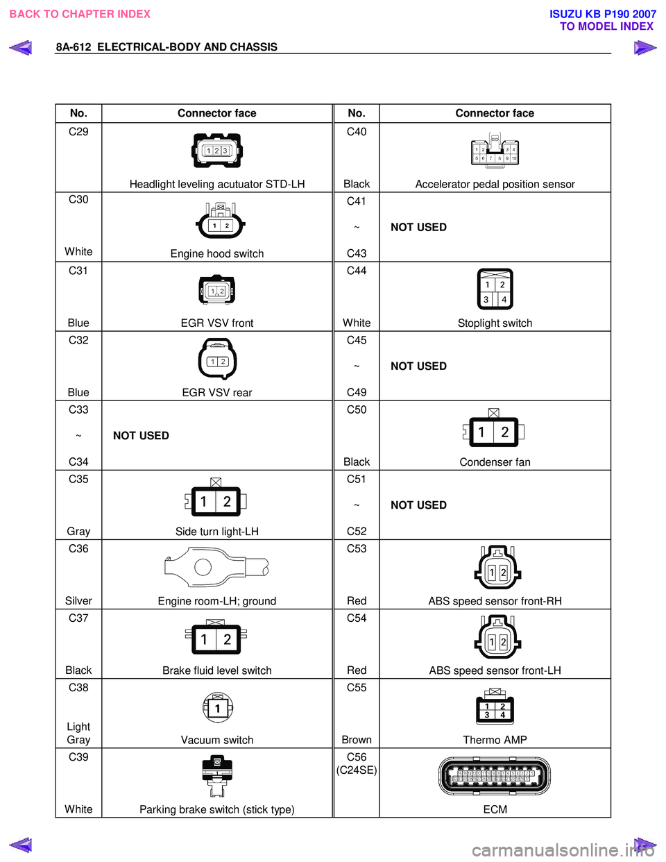
No. Connector face No. Connector face
C29
Headlight leveling acutuator STD-LH C40
BlackAccelerator pedal position sensor
C30
White
Engine hood switch C41
~
C43 NOT USED
C31
Blue
EGR VSV front C44
WhiteStoplight switch
C32
Blue
EGR VSV rear C45
~
C49 NOT USED
C33
~
C34 NOT USED C50
Black
Condenser fan
C35
Gray
Side turn light-LH C51
~
C52 NOT USED
C36
Silver
Engine room-LH; ground C53
Red ABS speed sensor front-RH
C37
Black
Brake fluid level switch C54
Red ABS speed sensor front-LH
C38
Light Gray
Vacuum switch C55
BrownThermo AMP
C39
White
Parking brake switch (stick type) C56
(C24SE)
ECM
BACK TO CHAPTER INDEX TO MODEL INDEXISUZU KB P190 2007
Page 5569 of 6020
ELECTRICAL-BODY AND CHASSIS 8A-631
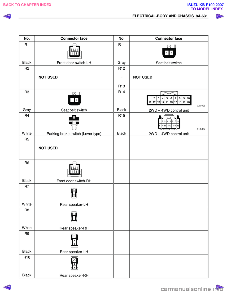
No. Connector face No. Connector face
R1
Black
Front door switch-LH R11
Gray Seat belt switch
R2
NOT USED R12
~
R13 NOT USED
R3
Gray
Seat belt switch R14
Black2W D – 4W D control unit
R4
White
Parking brake switch (Lever type) R15
Black2W D – 4W D control unit
R5
NOT USED
R6
Black
Front door switch-RH
R7
White
Rear speaker-LH
R8
White
Rear speaker-RH
R9
Black
Rear speaker-LH
R10
Black
Rear speaker-RH
BACK TO CHAPTER INDEX
TO MODEL INDEXISUZU KB P190 2007