Page 4448 of 6020
7A2-164 TRANSMISSION CONTROL SYSTEM (JR405E)
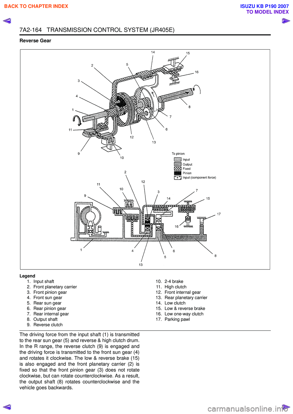
Reverse Gear
Legend1. Input shaft
2. Front planetary carrier
3. Front pinion gear
4. Front sun gear
5. Rear sun gear
6. Rear pinion gear
7. Rear internal gear
8. Output shaft
9. Reverse clutch 10. 2-4 brake
11 . H i g h c l u t c h
12. Front internal gear
13. Rear planetary carrier
14. Low clutch
15. Low & reverse brake
16. Low one-way clutch
17. Parking pawl
The driving force from the input shaft (1) is transmitted
to the rear sun gear (5) and reverse & high clutch drum.
In the R range, the reverse clutch (9) is engaged and
the driving force is transmitted to the front sun gear (4)
and rotates it clockwise. The low & reverse brake (15)
is also engaged and the front planetary carrier (2) is
fixed so that the front pinion gear (3) does not rotate
clockwise, but can rotate counterclockwise. As a result,
the output shaft (8) rotates counterclockwise and the
vehicle goes backwards.
BACK TO CHAPTER INDEX
TO MODEL INDEX
ISUZU KB P190 2007
Page 4449 of 6020
TRANSMISSION CONTROL SYSTEM (JR405E) 7A2-165
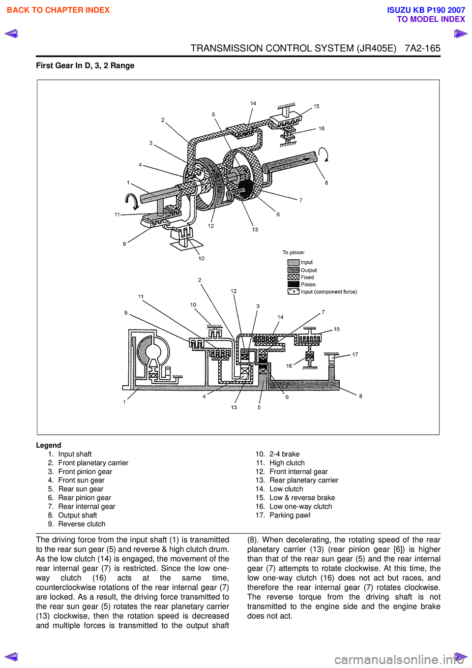
First Gear In D, 3, 2 Range
Legend1. Input shaft
2. Front planetary carrier
3. Front pinion gear
4. Front sun gear
5. Rear sun gear
6. Rear pinion gear
7. Rear internal gear
8. Output shaft
9. Reverse clutch 10. 2-4 brake
11. High clutch
12. Front internal gear
13. Rear planetary carrier
14. Low clutch
15. Low & reverse brake
16. Low one-way clutch
17. Parking pawl
The driving force from the input shaft (1) is transmitted
to the rear sun gear (5) and reverse & high clutch drum.
As the low clutch (14) is engaged, the movement of the
rear internal gear (7) is restricted. Since the low one-
way clutch (16) acts at the same time,
counterclockwise rotations of the rear internal gear (7)
are locked. As a result, the driving force transmitted to
the rear sun gear (5) rotates the rear planetary carrier
(13) clockwise, then the rotation speed is decreased
and multiple forces is transmitted to the output shaft (8). When decelerating, the rotating speed of the rear
planetary carrier (13) (rear pinion gear [6]) is higher
than that of the rear sun gear (5) and the rear internal
gear (7) attempts to rotate clockwise. At this time, the
low one-way clutch (16) does not act but races, and
therefore the rear internal gear (7) rotates clockwise.
The reverse torque from the driving shaft is not
transmitted to the engine side and the engine brake
does not act.
BACK TO CHAPTER INDEX
TO MODEL INDEX
ISUZU KB P190 2007
Page 4450 of 6020
7A2-166 TRANSMISSION CONTROL SYSTEM (JR405E)
First Gear In L Range
Legend1. Input shaft
2. Front planetary carrier
3. Front pinion gear
4. Front sun gear
5. Rear sun gear
6. Rear pinion gear
7. Rear internal gear
8. Output shaft
9. Reverse clutch 10. 2-4 brake
11 . H i g h c l u t c h
12. Front internal gear
13. Rear planetary carrier
14. Low clutch
15. Low & reverse brake
16. Low one-way clutch
17. Parking pawl
The basic mechanism is the same as in the D, 3, and 2
ranges. To apply the engine brake, the low & reverse
brake (15) is engaged to restrict the movement of the
low one-way clutch (16).
When decelerating, as the rear internal gear (7) is
fixed, reverse torque from the propeller shaft is
transmitted to the engine side so that the engine brake
is applied.
BACK TO CHAPTER INDEX
TO MODEL INDEX
ISUZU KB P190 2007
Page 4451 of 6020
TRANSMISSION CONTROL SYSTEM (JR405E) 7A2-167
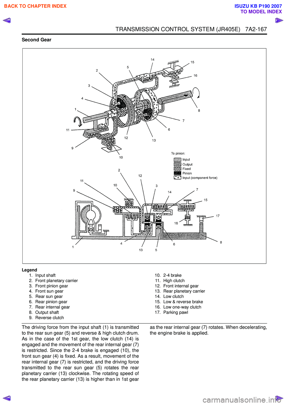
Second Gear
Legend1. Input shaft
2. Front planetary carrier
3. Front pinion gear
4. Front sun gear
5. Rear sun gear
6. Rear pinion gear
7. Rear internal gear
8. Output shaft
9. Reverse clutch 10. 2-4 brake
11. High clutch
12. Front internal gear
13. Rear planetary carrier
14. Low clutch
15. Low & reverse brake
16. Low one-way clutch
17. Parking pawl
The driving force from the input shaft (1) is transmitted
to the rear sun gear (5) and reverse & high clutch drum.
As in the case of the 1st gear, the low clutch (14) is
engaged and the movement of the rear internal gear (7)
is restricted. Since the 2-4 brake is engaged (10), the
front sun gear (4) is fixed. As a result, movement of the
rear internal gear (7) is restricted, and the driving force
transmitted to the rear sun gear (5) rotates the rear
planetary carrier (13) clockwise. The rotating speed of
the rear planetary carrier (13) is higher than in 1st gear as the rear internal gear (7) rotates. When decelerating,
the engine brake is applied.
BACK TO CHAPTER INDEX
TO MODEL INDEX
ISUZU KB P190 2007
Page 4452 of 6020
7A2-168 TRANSMISSION CONTROL SYSTEM (JR405E)
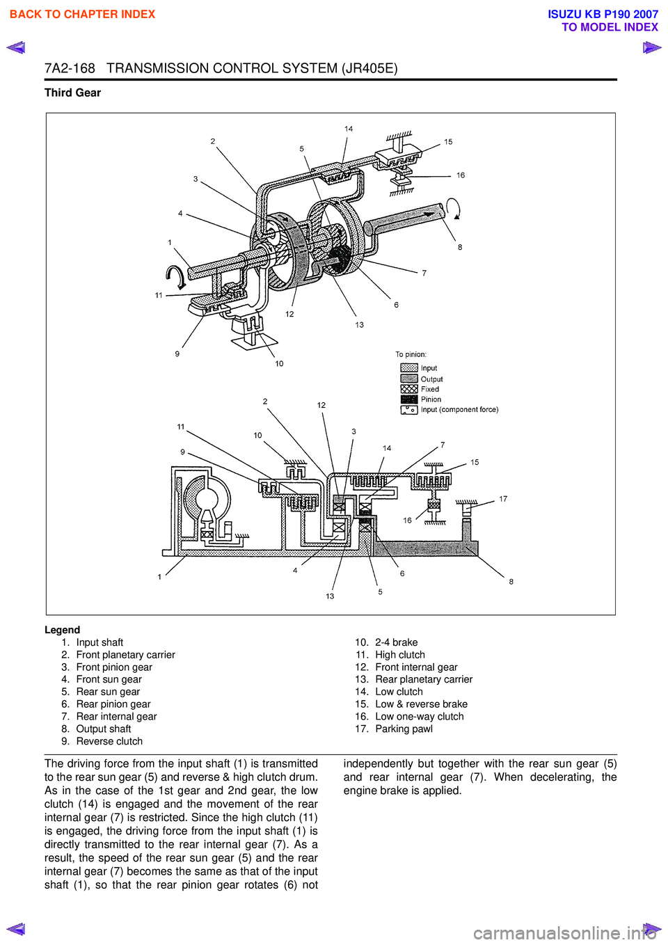
Third Gear
Legend1. Input shaft
2. Front planetary carrier
3. Front pinion gear
4. Front sun gear
5. Rear sun gear
6. Rear pinion gear
7. Rear internal gear
8. Output shaft
9. Reverse clutch 10. 2-4 brake
11 . H i g h c l u t c h
12. Front internal gear
13. Rear planetary carrier
14. Low clutch
15. Low & reverse brake
16. Low one-way clutch
17. Parking pawl
The driving force from the input shaft (1) is transmitted
to the rear sun gear (5) and reverse & high clutch drum.
As in the case of the 1st gear and 2nd gear, the low
clutch (14) is engaged and the movement of the rear
internal gear (7) is restricted. Since the high clutch (11)
is engaged, the driving force from the input shaft (1) is
directly transmitted to the rear internal gear (7). As a
result, the speed of the rear sun gear (5) and the rear
internal gear (7) becomes the same as that of the input
shaft (1), so that the rear pinion gear rotates (6) not independently but together with the rear sun gear (5)
and rear internal gear (7). When decelerating, the
engine brake is applied.
BACK TO CHAPTER INDEX
TO MODEL INDEX
ISUZU KB P190 2007
Page 4453 of 6020
TRANSMISSION CONTROL SYSTEM (JR405E) 7A2-169
Fourth Gear
Legend1. Input shaft
2. Front planetary carrier
3. Front pinion gear
4. Front sun gear
5. Rear sun gear
6. Rear pinion gear
7. Rear internal gear
8. Output shaft
9. Reverse clutch 10. 2-4 brake
11. High clutch
12. Front internal gear
13. Rear planetary carrier
14. Low clutch
15. Low & reverse brake
16. Low one-way clutch
17. Parking pawl
The driving force from the input shaft (1) is transmitted
to the rear sun gear (5) and reverse & high clutch drum.
Since the 2-4 brake (10) is engaged, the front sun gear
(4) is fixed. In addition to this the high clutch (11) is
engaged. As a result, the front pinion gear (6) rotates
itself together with other gears clockwise. This rotation
increases the speed of rotation of the front internal gear
(12) and is transmitted to the output shaft (8).
BACK TO CHAPTER INDEX
TO MODEL INDEX
ISUZU KB P190 2007
Page 4456 of 6020
7A3-2 ON-VEHICLE SERVICE (JR405E)
DESCRIPTION
Before performing on-vehicle service on the automatic
transmission, check that the engine idling speed and
general engine condition are normal.
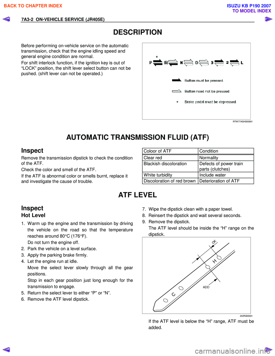
For shift interlock function, if the ignition key is out of
“LOCK” position, the shift lever select button can not be
pushed. (shift lever can not be operated.)
RTW 77ASH000901
AUTOMATIC TRANSMISSION FLUID (ATF)
Inspect
Remove the transmission dipstick to check the condition
of the ATF.
Check the color and smell of the ATF.
If the ATF is abnormal color or smells burnt, replace it
and investigate the cause of trouble.
Coloor of ATF Condition Clear red Normality
Blackish discoloration Defects of power train
parts (clutches)
W hite turbidity Include water
Discoloration of red brown Deterioration of ATF
ATF LEVEL
Inspect
Hot Level
1. W arm up the engine and the transmission by driving
the vehicle on the road so that the temperature
reaches around 80 °C (176 °F).
Do not turn the engine off.
2. Park the vehicle on a level surface.
3. Apply the parking brake firmly.
4. Let the engine run at idle.
Move the select lever slowly through all the gea
r
positions.
Stop in each gear position just long enough for the transmission to engage.
5. Return the select lever to either “P” or “N”.
6. Remove the ATF level dipstick.
7. W ipe the dipstick clean with a paper towel.
8. Reinsert the dipstick and wait several seconds.
9. Remove the dipstick.
The ATF level should be inside the “H” range on the dipstick.
242R300001
If the ATF level is below the “H” range, ATF must be added.
BACK TO CHAPTER INDEX
TO MODEL INDEX
ISUZU KB P190 2007
Page 4457 of 6020
ON-VEHICLE SERVICE (JR405E) 7A3-3
Cold Level
The vehicle must not have been driven so that the
temperature reaches around 20 °C (68 °F) before the
cold level check is made.
1. Park the vehicle on a level surface.
2. Apply the parking brake firmly.
3. Start the engine and allow it to warm up.
The engine coolant temperature gauge needle should be midway between the “C” mark and “H”
mark.
4. Let the engine run at idle.
Move the select lever slowly through all the gea
r
ranges.
Stop in each range just long enough for the transmission to engage.
5. Return the select lever either “P” or “N”.
6. Remove the ATF level dipstick.
7. W ipe the dipstick clean with a paper towel.
8. Reinsert the dipstick and wait several seconds.
9. Remove the dipstick.
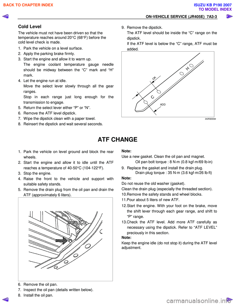
The ATF level should be inside the “C” range on the dipstick.
If the ATF level is below the “C” range, ATF must be added.
242R300002
ATF CHANGE
1. Park the vehicle on level ground and block the rear
wheels.
2. Start the engine and allow it to idle until the ATF reaches a temperature of 40-50 °C (104-122 °F).
3. Stop the engine.
4. Raise the front to the vehicle and support with suitable safety stands.
5. Remove the drain plug from the oil pan and drain the ATF (approximately 6 liters).
6. Remove the oil pan.
7. Inspect the oil pan (details written below).
8. Install the oil pan.
Note:
Use a new gasket. Clean the oil pan and magnet.
Oil pan bolt torque : 8 N ⋅m (0.8 kgf ⋅m/69 lb ⋅in)
9. Replace the gasket and install the drain plug.
Drain plug torque : 35 N ⋅m (3.6 kgf ⋅m/26 lb ⋅ft)
Note:
Do not reuse the old washer (gasket).
Clean the drain plug (especially the threaded section).
10.Remove the safety stands and wheel blocks.
11.Pour about 5 liters of new ATF.
12. Start the engine. W ith your foot on the brake, move the shift lever through each gear range, and shift to
“P” range.
13.Check the ATF level. Add more ATF carefully as necessary using the dipstick. Refer to “ATF LEVEL”
preciously in this section.
Note:
Keep the engine idle (do not stop it) during the ATF level
adjustment.
BACK TO CHAPTER INDEX
TO MODEL INDEX
ISUZU KB P190 2007