2007 ISUZU KB P190 differential
[x] Cancel search: differentialPage 657 of 6020

5A-64 BRAKE CONTROL SYSTEM
DTC C0238 (Flash Code 38) Front Speed Sensor Correlation
Step Action Value(s) Yes No
1 W ere the steps of the “Basic Diagnostic Flow Chart”
performed?
- Go to Step 2 Go to Basic
Diagnostic
Flow Chart
2 1. Check for the tire size of each wheels.
2. If the tire size is different, replace the tire.
3. If a problem is found, repair as necessary. W as a problem found? - Verify repair Go to Step 3
3 1. Check for the gear ratio of a front axle differential gear and a rear axle differential gear.
2. If the gear ratio is different, repair the gear ratio.
3. If a problem is found, repair as necessary. W as a problem found? - Verify repair Go to Step 4
4 Select “Display DTCs” with the Tech 2.
Note: Perform the various tests (actuator test, test
run, brake test, etc.) then observe the DTC with a
Tech 2.
Are any DTCs stored? - Go to Step 5 Verify repair
5 1. Check for a poor connection at the wheel speed sensor harness connector.
2. Check installation condition for wheel speed sensor.
3. If a problem is found, repair as necessary. W as a problem found? - Verify repair Go to Step 6
6 1. Check condition for sensor rotor.
2. If a problem is found, repair as necessary. W as a problem found? - Verify repair Go to Step 7
7 1. Ignition “OFF” disconnect the EHCU and wheel
speed sensor.
2. Check the circuit between EHCU and wheel speed sensor. (short ground, or short to voltage)
3. If a problem is found, repair as necessary. W as a problem found? - Verify repair Go to Step 8
8 1. Ignition “OFF”.
2. Check the EHCU circuit for an open, short to ground, or short to voltage. Also, check the EHCU
ignition feed circuit for an open or short to ground
and the EHCU ground circuit for an open or short to
voltage.
3. If a problem is found, repair as necessary. W as a problem found? - Verify repair Go to Step 9
9 1. Ignition “ON”, engine “OFF”.
2. Select “Display DTCs” with the Tech 2. Note: Perform the various tests (actuator test, test
run, brake test, etc.) then observe the DTC with a
Tech 2.
Are any DTCs stored? - Go to Step 10 Verify repair
BACK TO CHAPTER INDEX
TO MODEL INDEX
ISUZU KB P190 2007
Page 842 of 6020

ENGINE MECHANICAL 6A – 37
REMOVAL AND INSTALLATION
Read this section carefully before performing any removal and installation procedure. This section gives
you important points as well as the order of operation. Be sure that you understand everything in this section before
you begin.
Removal
P1010011
1. Battery
1) Disconnect the battery cable and the grounding cable from the battery terminals.
2) Remove the battery clamp. Take care not to accidentally short the battery with the wrench or some
other tool.
3) Remove the battery.
4) Disconnect the battery cable at the starter motor and the ground cable at the cylinder body.
2. Engine Hood Apply setting marks to the engine hood and the engine
hood hinges before removing the engine hood. This will
facilitate reinstallation of the engine hood to its original
position.
3. Supporting the Vehicle 1) Jack up the vehicle.
2) Place chassis stands at the front and the rear of the vehicle.
4. Under cover (for 4x4 model) 5. Rear propeller shaft 1) Remove the propeller shaft flange yoke at the rear differential.
2) Remove the center bearing retainer bolts.
3) Remove the propeller shaft together with the center bearing from the transmission mainshaft spline.
F06R300006 P1010002
BACK TO CHAPTER INDEX
TO MODEL INDEX
ISUZU KB P190 2007
Page 1672 of 6020

ENGINE CONTROL SYSTEM (4JK1/4JJ1) 6E-55
Scan Tool Output Controls
Scan Tool Output ControlDescriptions
Fuel Supply Pump Learn Resetting The purpose of this test to reset the fuel supply pump adjustment value.
Important: The fuel supply pump relearn procedure must be done when the fuel supply
pump or engine is replaced, or an ECM from another vehicle is installed. Refer to Fuel
Supply Pump Replacement.
Fuel Pressure Control The purpose of this test is for checking whether the fuel rail pressure is changing when
commanded within 30 to 80MPa (4,350 to 11,600psi) when commanded. Faulty fuel supply
pump, fuel rail pressure (FRP) regulator, pressure limiter valve or other fuel lines could be
considered if the differential fuel rail pressure is large.
Pilot Injection Control The purpose of this test is for checking whether the pilot fuel injection is operated when it is
commanded to ON/ OFF. Faulty injector(s) could be considered if engine noise does not
change when commanded OFF.
Injection Timing Control The purpose of this test is for checking whether the main injection timing is changing when
commanded Retard/ Advance within -5 to 5 °CA.
Injector Force Drive The purpose of this test is for checking whether the fuel injector is correctly operating when
commanded ON. Faulty injector(s) could be considered if it does not create a clicking noise
(solenoid operating noise), contains an interrupted noise or has abnormal noise when
commanded ON.
Cylinder Balance Test The purpose of this test is for checking whether the fuel injector is operating when
commanded ON/ OFF. Faulty injector(s) could be considered if engine does not change
speed when commanded OFF.
Intake Throttle Solenoid Control The purpose of this test is for checking whether the intake throttle valve is correctly moved
with command. Restricted valve movement by foreign materials, excessive deposits or a
faulty valve could be considered if the position difference is large.
EGR Solenoid Control The purpose of this test is for checking whether the EGR valve is correctly moved with
command. Restricted valve movement by foreign materials, excessive deposits or a faulty
valve could be considered if the position difference is large.
Swirl Control Solenoid Control The purpose of this test is for checking whether the swirl control solenoid is operating when
commanded ON. Faulty circuit(s) or a faulty solenoid could be considered if not energizing
when commanded ON.
Turbocharger Solenoid Control The purpose of this test is for checking whether the turbocharger nozzle control actuator is
correctly moved with command. Restricted actuator movement by foreign materials,
excessive deposits, misrouted vacuum hoses, a faulty solenoid or a faulty actuator could be
considered if the actuator is not moved correctly.
Glow Relay Control The purpose of this test is for checking whether the glow relay is operating when
commanded ON. Faulty circuit(s) or a faulty glow relay could be considered if not energizing
when commanded ON.
Glow Plug Lamp Control The purpose of this test is for checking whether the glow indicator lamp is operating when
commanded ON. Faulty circuit(s) or an open circuit could be considered when not operating
when commanded ON.
Malfunction Indicator Lamp (MIL) Control The purpose of this test is for checking whether the MIL is operating when commanded ON.
Faulty circuit(s) or an open circuit could be considered when not operating when
commanded ON.
Service Vehicle Soon (SVS) Lamp Control The purpose of this test is for checking whether the SVS lamp is operating when
commanded ON. Faulty circuit(s) or an open circuit could be considered when not operating
when commanded ON.
Cruise Main Lamp Control The purpose of this test is for checking whether the cruise main lamp is operating when
commanded ON. Faulty circuit(s) or an open circuit could be considered when not operating
when commanded ON.
Cruise Set Lamp Control The purpose of this test is for checking whether the cruise set lamp is operating when
commanded ON. Faulty circuit(s) or an open circuit could be considered when not operating
when commanded ON.
BACK TO CHAPTER INDEX
TO MODEL INDEX
ISUZU KB P190 2007
Page 1907 of 6020
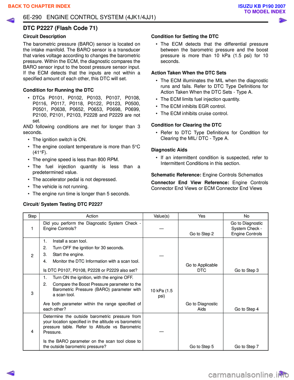
6E-290 ENGINE CONTROL SYSTEM (4JK1/4JJ1)
DTC P2227 (Flash Code 71)
Circuit Description
The barometric pressure (BARO) sensor is located on
the intake manifold. The BARO sensor is a transducer
that varies voltage according to changes the barometric
pressure. Within the ECM, the diagnostic compares the
BARO sensor input to the boost pressure sensor input.
If the ECM detects that the inputs are not within a
specified amount of each other, this DTC will set.
Condition for Running the DTC • DTCs P0101, P0102, P0103, P0107, P0108, P0116, P0117, P0118, P0122, P0123, P0500,
P0501, P0638, P0652, P0653, P0698, P0699,
P2100, P2101, P2103, P2228 and P2229 are not
set.
AND following conditions are met for longer than 3
seconds.
• The ignition switch is ON.
• The engine coolant temperature is more than 5 °C
(41 °F).
• The engine speed is less than 800 RPM.
• The fuel injection quantity is less than a predetermined value.
• The accelerator pedal is not depressed.
• The vehicle is not running.
• The engine run time is longer than 5 seconds. Condition for Setting the DTC
• The ECM detects that the differential pressure between the barometric pressure and the boost
pressure is more than 10 kPa (1.5 psi) for 10
seconds.
Action Taken When the DTC Sets • The ECM illuminates the MIL when the diagnostic runs and fails. Refer to DTC Type Definitions for
Action Taken When the DTC Sets - Type A.
• The ECM limits fuel injection quantity.
• The ECM inhibits EGR control.
• The ECM inhibits cruise control.
Condition for Clearing the DTC • Refer to DTC Type Definitions for Condition for Clearing the MIL/ DTC - Type A.
Diagnostic Aids • If an intermittent condition is suspected, refer to Intermittent Conditions in this section.
Schematic Reference: Engine Controls Schematics
Connector End View Reference: Engine Controls
Connector End Views or ECM Connector End Views
Circuit/ System Testing DTC P2227
Step Action Value(s)Yes No
1 Did you perform the Diagnostic System Check -
Engine Controls? —
Go to Step 2 Go to Diagnostic
System Check -
Engine Controls
2 1. Install a scan tool.
2. Turn OFF the ignition for 30 seconds.
3. Start the engine.
4. Monitor the DTC Information with a scan tool.
Is DTC P0107, P0108, P2228 or P2229 also set? —
Go to Applicable DTC Go to Step 3
3 1. Turn ON the ignition, with the engine OFF.
2. Compare the Boost Pressure parameter to the Barometric Pressure (BARO) parameter with
a scan tool.
Are both parameter within the range specified of
each other? 10 kPa (1.5
psi)
Go to Diagnostic Aids Go to Step 4
4 Determine the outside barometric pressure from
your location specified in the altitude vs barometric
pressure table. Refer to Altitude vs Barometric
Pressure.
Is the BARO parameter on the scan tool close to
the outside barometric pressure? —
Go to Step 5 Go to Step 7
BACK TO CHAPTER INDEX
TO MODEL INDEX
ISUZU KB P190 2007
Page 2122 of 6020
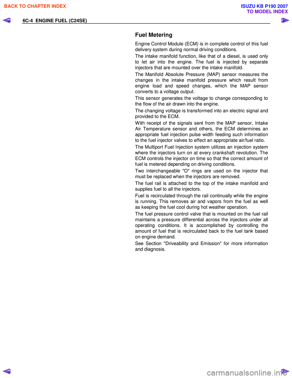
6C-4 ENGINE FUEL (C24SE)
Fuel Metering
Engine Control Module (ECM) is in complete control of this fuel
delivery system during normal driving conditions.
The intake manifold function, like that of a diesel, is used onl
y
to let air into the engine. The fuel is injected by separate
injectors that are mounted over the intake manifold.
The Manifold Absolute Pressure (MAP) sensor measures the
changes in the intake manifold pressure which result from
engine load and speed changes, which the MAP senso
r
converts to a voltage output.
This sensor generates the voltage to change corresponding to
the flow of the air drawn into the engine.
The changing voltage is transformed into an electric signal and
provided to the ECM.
W ith receipt of the signals sent from the MAP sensor, Intake
Air Temperature sensor and others, the ECM determines an
appropriate fuel injection pulse width feeding such information
to the fuel injector valves to effect an appropriate air/fuel ratio.
The Multiport Fuel Injection system utilizes an injection system
where the injectors turn on at every crankshaft revolution. The
ECM controls the injector on time so that the correct amount o
f
fuel is metered depending on driving conditions.
Two interchangeable "O" rings are used on the injector that
must be replaced when the injectors are removed.
The fuel rail is attached to the top of the intake manifold and
supplies fuel to all the injectors.
Fuel is recirculated through the rail continually while the engine
is running. This removes air and vapors from the fuel as well
as keeping the fuel cool during hot weather operation.
The fuel pressure control valve that is mounted on the fuel rail
maintains a pressure differential across the injectors under all
operating conditions. It is accomplished by controlling the
amount of fuel that is recirculated back to the fuel tank based
on engine demand.
See Section "Driveability and Emission" for more information
and diagnosis.
BACK TO CHAPTER INDEX
TO MODEL INDEX
ISUZU KB P190 2007
Page 2160 of 6020
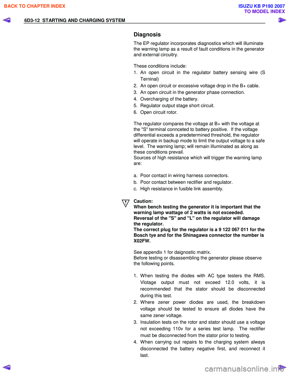
6D3-12 STARTING AND CHARGING SYSTEM
Diagnosis
The EP regulator incorporates diagnostics which will illuminate
the warning lamp as a result of fault conditions in the generator
and external circuitry.
These conditions include:
1.
An open circuit in the regulator battery sensing wire (S
Terninal)
2. An open circuit or excessive voltage drop in the B+ cable.
3. An open circuit in the generator phase connection.
4. Overcharging of the battery.
5. Regulator output stage short circuit.
6. Open circuit rotor.
The regulator compares the voltage at B+ with the voltage at
the "S" terminal connceted to battery positive. If the voltage
differential exceeds a predetermined threshold, the regulator
will operate in backup mode to limit the output voltage to a safe
level. The warning lamp; will remain illuminated as along as
these conditions prevail.
Sources of high resistance which will trigger the warning lamp
are:
a. Poor contact in wiring harness connectors.
b. Poor contact between rectifier and regulator.
c. High resistance in fusible link assembly.
Caution:
When bench testing the generator it is important that the
warning lamp wattage of 2 watts is not exceeded.
Reversal of the "S" and "L" on the regulator will damage
the regulator.
The correct plug for the regulator is a 9 122 067 011 for the
Bosch tye and for the Shinagawa connector the number is
X02FW.
See appendix 1 for daignostic matrix.
Before testing or disassembling the generator please observe
the following points.
1. W hen testing the diodes with AC type testers the RMS.
Vlotage output must not exceed 12.0 volts, it is
recommended that the stator should be disconnected
during this test.
2. W here zener power diodes are used, the breakdown voltage should be tested to ensure all diodes have the
same zener voltage.
3. Insulation tests on the rotor and stator should use a voltage not exceeding 110v for a series test lamp. The rectifie
r
must be disconnected from the stator prior to testing.
4. W hen carrying out repairs to the charging system always disconnected the battery negative first, and reconnect it
last.
BACK TO CHAPTER INDEX
TO MODEL INDEX
ISUZU KB P190 2007
Page 3276 of 6020
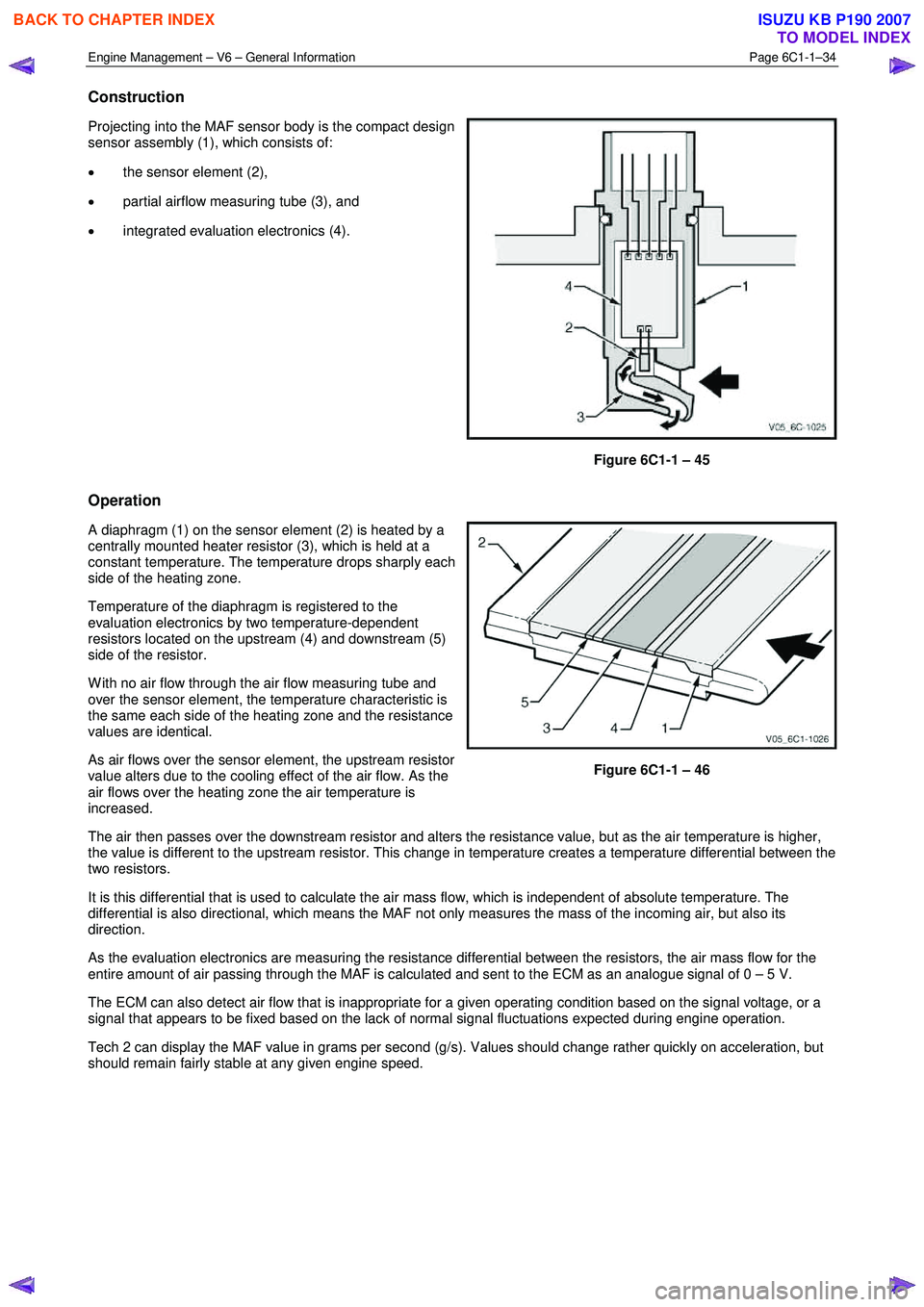
Engine Management – V6 – General Information Page 6C1-1–34
Construction
Projecting into the MAF sensor body is the compact design
sensor assembly (1), which consists of:
• the sensor element (2),
• partial airflow measuring tube (3), and
• integrated evaluation electronics (4).
Figure 6C1-1 – 45
Operation
A diaphragm (1) on the sensor element (2) is heated by a
centrally mounted heater resistor (3), which is held at a
constant temperature. The temperature drops sharply each
side of the heating zone.
Temperature of the diaphragm is registered to the
evaluation electronics by two temperature-dependent
resistors located on the upstream (4) and downstream (5)
side of the resistor.
W ith no air flow through the air flow measuring tube and
over the sensor element, the temperature characteristic is
the same each side of the heating zone and the resistance
values are identical.
As air flows over the sensor element, the upstream resistor
value alters due to the cooling effect of the air flow. As the
air flows over the heating zone the air temperature is
increased.
Figure 6C1-1 – 46
The air then passes over the downstream resistor and alters the resistance value, but as the air temperature is higher,
the value is different to the upstream resistor. This change in temperature creates a temperature differential between the
two resistors.
It is this differential that is used to calculate the air mass flow, which is independent of absolute temperature. The
differential is also directional, which means the MAF not only measures the mass of the incoming air, but also its
direction.
As the evaluation electronics are measuring the resistance differential between the resistors, the air mass flow for the
entire amount of air passing through the MAF is calculated and sent to the ECM as an analogue signal of 0 – 5 V.
The ECM can also detect air flow that is inappropriate for a given operating condition based on the signal voltage, or a
signal that appears to be fixed based on the lack of normal signal fluctuations expected during engine operation.
Tech 2 can display the MAF value in grams per second (g/s). Values should change rather quickly on acceleration, but
should remain fairly stable at any given engine speed.
BACK TO CHAPTER INDEX
TO MODEL INDEX
ISUZU KB P190 2007
Page 4098 of 6020
ON-VEHICLE SERVICE (AW30–40LE) 7A3-13
Evaluation
i. If there is no 1→2 upshift:
• Solenoid S2 is stuck
• 1–2 shift valve is stuck
ii. If there is no 2 →3 upshift:
• Solenoid S1 is stuck
• 2–3 shift valve is stuck
iii. If there is no 3 →OD upshift (throttle valve opening
1/2):
• Solenoid S2 is stuck
• 3–OD shift valve is stuck
iv. If the shift point is defective: Refer to TROUBLESHOOTING CHART in this
section.
v. If the lock-up is defective: Refer to TROUBLESHOOTING CHART in this
section.
2. In the same manner, check the shock and slip at the 1→ 2, 2 →3 and 3 →OD upshifts.
NOTE: Drive the vehicle on level ground.
Evaluation
If the shock is excessive:
Refer to TROUBLESHOOTING CHART in this section. 3. Run at “D" position lock-up or OD gear and check fo
r
abnormal noise and vibration.
NOTE: The check for the cause of abnormal noise and
vibration must be made with extreme care as it could
also be due to loss of balance in the propeller shaft,
differential, the torque converter, etc. or insufficient
bending, rigidity, etc. in the power train.
RUW 37ASH000201
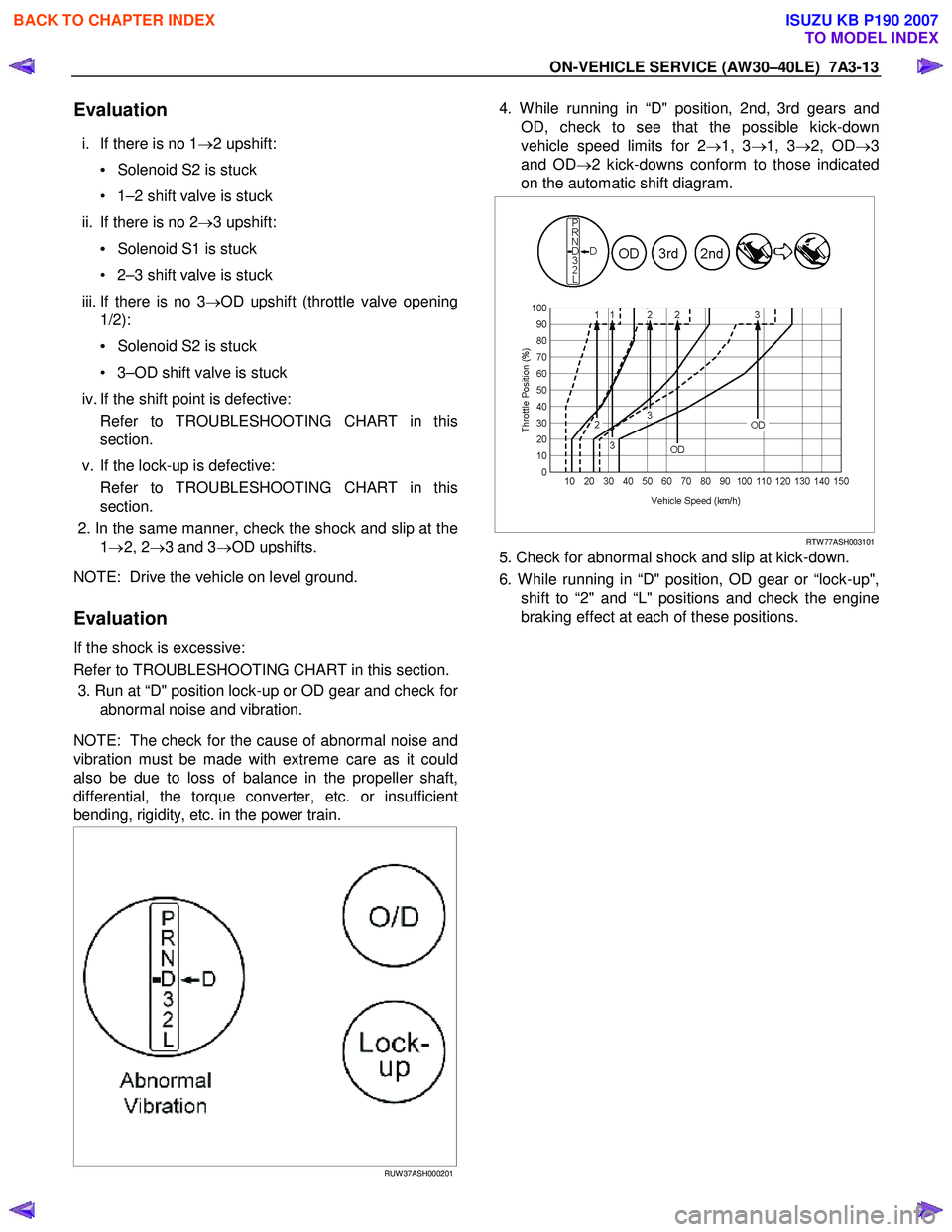
4. W hile running in “D" position, 2nd, 3rd gears and
OD, check to see that the possible kick-down
vehicle speed limits for 2 →1, 3 →1, 3 →2, OD →3
and OD →2 kick-downs conform to those indicated
on the automatic shift diagram.
RTW 77ASH003101
5. Check for abnormal shock and slip at kick-down.
6. W hile running in “D" position, OD gear or “lock-up", shift to “2" and “L" positions and check the engine
braking effect at each of these positions.
BACK TO CHAPTER INDEX
TO MODEL INDEX
ISUZU KB P190 2007