Page 4125 of 6020
7A3-40 ON-VEHICLE SERVICE (AW30–40LE)
Removal
NOTE: Before removing transmission and transfer
assembly from vehicle, change the transfer mode to
4 ×2 using the 4 ×4 push button switch on dash panel.
1. Disconnect battery ground cable.
2. Raise and support vehicle with suitable stands.
3. Remove the drain plug and drain the transmission oil.
4. Remove the front propeller shaft. (4 ×4 only)
NOTE: Apply alignment marks on the flange at both
front and rear sides.
5. Remove the rear propeller shaft.
NOTE: Apply alignment marks on the differential side.
RTW 77BSH000201
6. Disconnect the 2W D-4W D switch connector (1),
neutral switch connector (2), actuator connecto
r
(3) and speed sensor connector (4).
RTW 77ASH001801
RTW 77ASH001901
RTW 77ASH002001
7. Disconnect two harness clips (1) of the transfer
upper side.
1
1
RTW 77ASH001601
BACK TO CHAPTER INDEX
TO MODEL INDEX
ISUZU KB P190 2007
Page 4392 of 6020

7A2-108 TRANSMISSION CONTROL SYSTEM (JR405E)
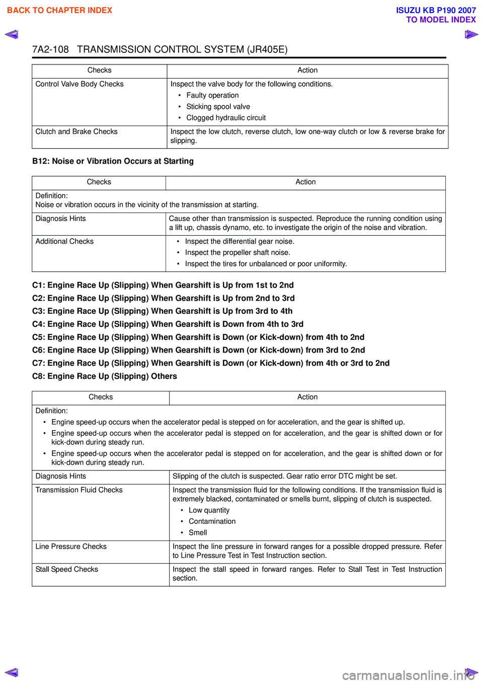
B12: Noise or Vibration Occurs at Starting
C1: Engine Race Up (Slipping) When Gearshift is Up from 1st to 2nd
C2: Engine Race Up (Slipping) When Gearshift is Up from 2nd to 3rd
C3: Engine Race Up (Slipping) When Gearshift is Up from 3rd to 4th
C4: Engine Race Up (Slipping) When Gearshift is Down from 4th to 3rd
C5: Engine Race Up (Slipping) When Gearshift is Down (or Kick-down) from 4th to 2nd
C6: Engine Race Up (Slipping) When Gearshift is Down (or Kick-down) from 3rd to 2nd
C7: Engine Race Up (Slipping) When Gearshift is Down (or Kick-down) from 4th or 3rd to 2nd
C8: Engine Race Up (Slipping) Others
Control Valve Body Checks Inspect the valve body for the following conditions.
• Faulty operation
• Sticking spool valve
• Clogged hydraulic circuit
Clutch and Brake Checks Inspect the low clutch, reverse clutch, low one-way clutch or low & reverse brake for
slipping.
Checks
Action
ChecksAction
Definition:
Noise or vibration occurs in the vicinity of the transmission at starting.
Diagnosis Hints Cause other than transmission is suspected. Reproduce the running condition using
a lift up, chassis dynamo, etc. to investigate the origin of the noise and vibration.
Additional Checks • Inspect the differential gear noise.
• Inspect the propeller shaft noise.
• Inspect the tires for unbalanced or poor uniformity.
Checks Action
Definition: • Engine speed-up occurs when the accelerator pedal is stepped on for acceleration, and the gear is shifted up.
• Engine speed-up occurs when the accelerator pedal is stepped on for acceleration, and the gear is shifted down or for kick-down during steady run.
• Engine speed-up occurs when the accelerator pedal is stepped on for acceleration, and the gear is shifted down or for kick-down during steady run.
Diagnosis Hints Slipping of the clutch is suspected. Gear ratio error DTC might be set.
Transmission Fluid Checks Inspect the transmission fluid for the following conditions. If the transmission fluid is
extremely blacked, contaminated or smells burnt, slipping of clutch is suspected.
• Low quantity
• Contamination
•Smell
Line Pressure Checks Inspect the line pressure in forward ranges for a possible dropped pressure. Refer
to Line Pressure Test in Test Instruction section.
Stall Speed Checks Inspect the stall speed in forward ranges. Refer to Stall Test in Test Instruction
section.
BACK TO CHAPTER INDEX
TO MODEL INDEX
ISUZU KB P190 2007
Page 4399 of 6020

TRANSMISSION CONTROL SYSTEM (JR405E) 7A2-115
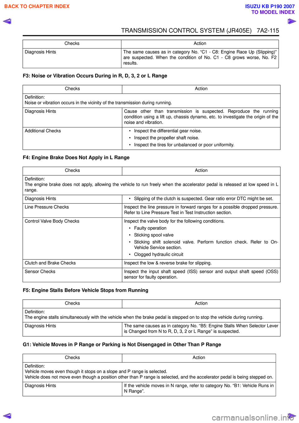
F3: Noise or Vibration Occurs During in R, D, 3, 2 or L Range
F4: Engine Brake Does Not Apply in L Range
F5: Engine Stalls Before Vehicle Stops from Running
G1: Vehicle Moves in P Range or Parking is Not Disengaged in Other Than P Range
Diagnosis Hints The same causes as in category No. “C1 - C8: Engine Race Up (Slipping)”
are suspected. When the condition of No. C1 - C8 grows worse, No. F2
results.
Checks Action
Definition:
Noise or vibration occurs in the vicinity of the transmission during running.
Diagnosis Hints Cause other than transmission is suspected. Reproduce the running
condition using a lift up, chassis dynamo, etc. to investigate the origin of the
noise and vibration.
Additional Checks • Inspect the differential gear noise.
• Inspect the propeller shaft noise.
• Inspect the tires for unbalanced or poor uniformity.
Checks
Action
Checks Action
Definition:
The engine brake does not apply, allowing the vehicle to run freely when the accelerator pedal is released at low speed in L
range.
Diagnosis Hints • Slipping of the clutch is suspected. Gear ratio error DTC might be set.
Line Pressure Checks Inspect the line pressure in forward ranges for a possible dropped pressure.
Refer to Line Pressure Test in Test Instruction section.
Control Valve Body Checks Inspect the valve body for the following conditions.
• Faulty operation
• Sticking spool valve
• Sticking shift solenoid valve. Perform function check. Refer to On- Vehicle Service section.
• Clogged hydraulic circuit
Clutch and Brake Checks Inspect the low & reverse brake for slipping.
Sensor Checks Inspect the input shaft speed (ISS) sensor and output shaft speed (OSS)
sensor for faulty operation.
Checks Action
Definition:
The engine stalls simultaneously with the vehicle when the brake pedal is stepped on to stop the vehicle during running.
Diagnosis Hints The same causes as in category No. “B5: Engine Stalls When Selector Lever
is Changed from N to R, D, 3, 2 or L Range” is suspected.
Checks Action
Definition:
Vehicle moves even though it stops on a slope and P range is selected.
Vehicle does not move even though a position other than P range is selected, and the accelerator pedal is being stepped on.
Diagnosis Hints If the vehicle moves in N range, refer to category No. “B1: Vehicle Runs in
N Range”.
BACK TO CHAPTER INDEX
TO MODEL INDEX
ISUZU KB P190 2007
Page 4410 of 6020

7A2-126 TRANSMISSION CONTROL SYSTEM (JR405E)
• Sticking of low & reverse brake solenoid valve
• Refer to symptom diagnosis No. A2: Vehicle Dose Not Run in R Range
6. If there is no parking. • Faulty parking pawl
• Refer to symptom diagnosis No. G1: Vehicle Moves in P Range or Parking Gear in Not
Disengaged other than P Range.
Notice: The check for the cause of abnormal noise and
vibration must be made with extreme care as it could
also be due to loss of balance in the propeller shaft,
differential, the torque converter, etc. Or insufficient
bending, rigidity, etc. in the powertrain.
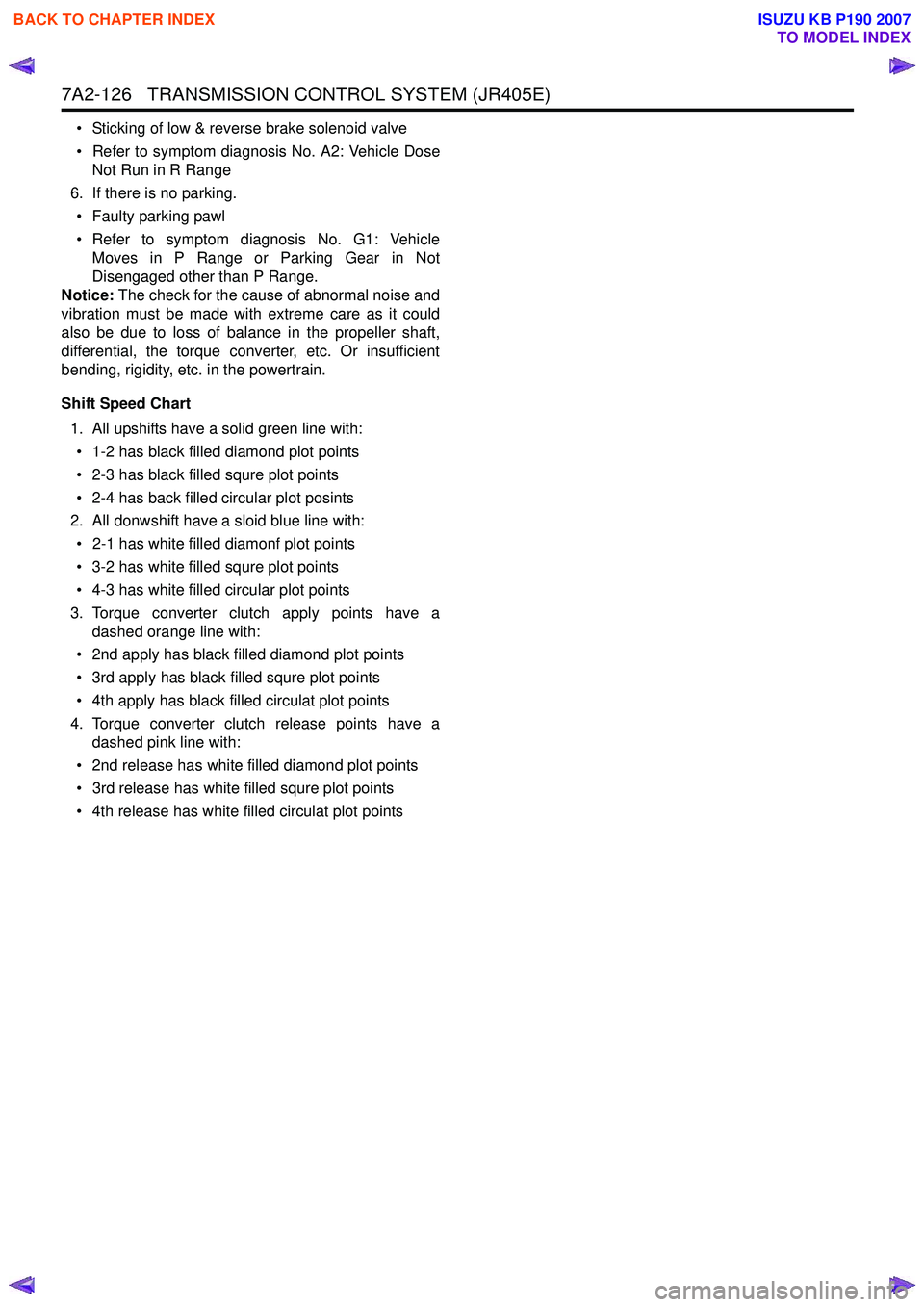
Shift Speed Chart 1. All upshifts have a solid green line with:• 1-2 has black filled diamond plot points
• 2-3 has black filled squre plot points
• 2-4 has back filled circular plot posints
2. All donwshift have a sloid blue line with:
• 2-1 has white filled diamonf plot points
• 3-2 has white filled squre plot points
• 4-3 has white filled circular plot points
3. Torque converter clutch apply points have a dashed orange line with:
• 2nd apply has black filled diamond plot points
• 3rd apply has black filled squre plot points
• 4th apply has black filled circulat plot points
4. Torque converter clutch release points have a dashed pink line with:
• 2nd release has white filled diamond plot points
• 3rd release has white filled squre plot points
• 4th release has white filled circulat plot points
BACK TO CHAPTER INDEX
TO MODEL INDEX
ISUZU KB P190 2007
Page 4611 of 6020
MANUAL TRANSMISSION 7B1-5
Rear Oil Seal
Disassembled View
220R300030
Legend
(1) Rear Propeller Shaft (2) Rear Oil Seal
Removal
1. Raise and support the vehicle with suitable jack
stands.
2. Remove the propeller shaft flange yoke bolts and nuts at the differential side.
3. Remove center bearing from the crossmember.
4. Remove prepeller shaft from the transmission main shaft spline.
Refer to the section “Rear Propeller Shaft”.
5. Use a screwdriver to pry the rear oil seal from the rear cover.
Installation
1. Install a new oil seal using the installer 5-8522-0050- 0.
220RS044
2. Insert the splined yoke into the transimission
mainshaft spline.
3. Install the propeller shaft flange yoke to the drive pinion flange.
BACK TO CHAPTER INDEX
TO MODEL INDEX
ISUZU KB P190 2007
Page 4615 of 6020
MANUAL TRANSMISSION 7B1-9
6. Remove the gear control lever.
7. Raise and support the vehicle with suitable stands.
8. Remove the rear propeller shaft.
NOTE: Apply alignment marks on the flange at the
differential side.
401RS023
9. Loosen the front exhaust pipe fixing nuts at the engine side but do not remove them. (Diesel engine
only)
RTW 67BSH000101
10. Disconnect the harness connectors and clips on the
transmission.
• Neutral Switch
• Back up Switch
• Car Speed Sensor
11. Remove the fuel pipe bracket with pipes from the transmission.
Diesel engine
220R300012
Legend
(1) Bolt
(2) Nut
(3) Fuel Pipe Assembly
C24SE
Scan-1
BACK TO CHAPTER INDEX
TO MODEL INDEX
ISUZU KB P190 2007
Page 4669 of 6020
MANUAL TRANSMISSION 7B1-63
6. Remove the gear control lever.
7. Raise and support the vehicle with suitable stands.
8. Remove the rear propeller shaft.
NOTE: Apply alignment marks on the flange at the
differential side.
9. Remove the front propeller shaft.
NOTE:
Apply alignment marks on the flange at both
front and rear sides.
401RS023
10. Loosen the front exhaust pipe fixing nuts at the engine side but do not remove them. (Diesel engine
only)
RTW 67BSH000101
11. Disconnect the harness connectors and clips on the
transmission and transfer.
• Neutral Switch: Transmission
• Back up Switch
• Actuator
• 2W D-4W D Switch
• Neutral Switch: Transfer
• Car Speed Sensor
810R300069
Legend
(1) Neutral Switch Connector: Transmission
(2) Back up Switch Connector
(3) Speed Sensor Connector
(4) Actuator Connector
(5) 2W D - 4W D Switch Connector
(6) Neutral Switch Connector: Transfer
BACK TO CHAPTER INDEX
TO MODEL INDEX
ISUZU KB P190 2007
Page 4728 of 6020
Manual Transmission (MUX) 7B1-9
• Apply alignment marks on the flange at thedifferential side.
9. Remove the front propeller shaft. (4x4 model) • Apply alignment marks on the flange at bothfront and rear side. 10. Disconnect the harness connectors and clips on
the transmission.
Legend 1. Neutral switch connector
2. Clutch damper valve connector
Legend 3. Clip
4. Reverse switch connector
5. 1st switch connector
RTW77BSH000201
RTW77BSH000201
RTW77BSH006601
1
2
RTW77BSH006701
3
3 54
BACK TO CHAPTER INDEX
TO MODEL INDEX
ISUZU KB P190 2007