2007 ISUZU KB P190 torque
[x] Cancel search: torquePage 3446 of 6020
Engine Management – V6 – Diagnostics Page 6C1-2–168
• To assist diagnosis, refer to 3 W iring Diagrams and Connector Charts in this Section, for the system wiring
diagram and connector charts.
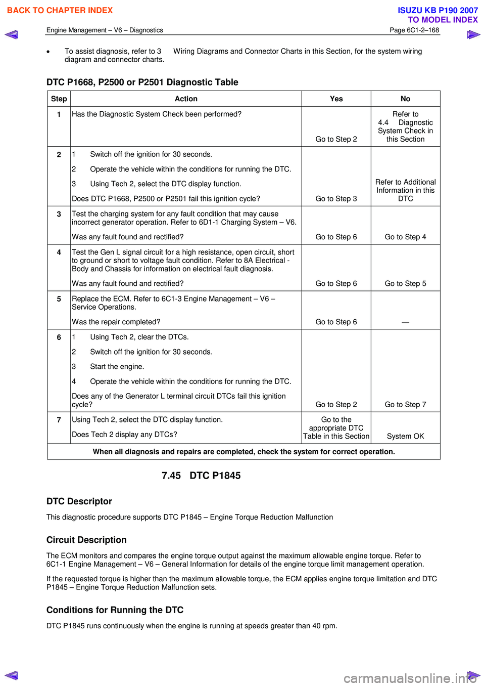
DTC P1668, P2500 or P2501 Diagnostic Table
Step Action Yes No
1 Has the Diagnostic System Check been performed?
Go to Step 2 Refer to
4.4 Diagnostic
System Check in this Section
2 1 Switch off the ignition for 30 seconds.
2 Operate the vehicle within the conditions for running the DTC.
3 Using Tech 2, select the DTC display function.
Does DTC P1668, P2500 or P2501 fail this ignition cycle? Go to Step 3 Refer to Additional
Information in this DTC
3 Test the charging system for any fault condition that may cause
incorrect generator operation. Refer to 6D1-1 Charging System – V6.
W as any fault found and rectified? Go to Step 6 Go to Step 4
4 Test the Gen L signal circuit for a high resistance, open circuit, short
to ground or short to voltage fault condition. Refer to 8A Electrical -
Body and Chassis for information on electrical fault diagnosis.
W as any fault found and rectified? Go to Step 6 Go to Step 5
5 Replace the ECM. Refer to 6C1-3 Engine Management – V6 –
Service Operations.
W as the repair completed? Go to Step 6 —
6 1 Using Tech 2, clear the DTCs.
2 Switch off the ignition for 30 seconds.
3 Start the engine.
4 Operate the vehicle within the conditions for running the DTC.
Does any of the Generator L terminal circuit DTCs fail this ignition
cycle? Go to Step 2 Go to Step 7
7 Using Tech 2, select the DTC display function.
Does Tech 2 display any DTCs? Go to the
appropriate DTC
Table in this Section System OK
When all diagnosis and repairs are completed, check the system for correct operation.
7.45 DTC P1845
DTC Descriptor
This diagnostic procedure supports DTC P1845 – Engine Torque Reduction Malfunction
Circuit Description
The ECM monitors and compares the engine torque output against the maximum allowable engine torque. Refer to
6C1-1 Engine Management – V6 – General Information for details of the engine torque limit management operation.
If the requested torque is higher than the maximum allowable torque, the ECM applies engine torque limitation and DTC
P1845 – Engine Torque Reduction Malfunction sets.
Conditions for Running the DTC
DTC P1845 runs continuously when the engine is running at speeds greater than 40 rpm.
BACK TO CHAPTER INDEX
TO MODEL INDEX
ISUZU KB P190 2007
Page 3447 of 6020
Engine Management – V6 – Diagnostics Page 6C1-2–169
Conditions for Setting the DTC
The engine torque output exceeds the maximum allowable torque output for 10 minutes.
Conditions for Clearing the DTC
DTC P1845 – Engine Torque Reduction Malfunction is a Type ‘C’ DTC. Refer to 1.4 Diagnostic Trouble Codes in this
Section, for action taken when a Type ‘C’ DTC sets and conditions for clearing Type ‘C’ DTC.
Additional Information
• Refer to 6C1-1 Engine Management – V6 – General Information for details of the Engine Torque Limit
Management operation.
• For an intermittent fault condition, refer to 5.2 Intermittent Fault Conditions in this Section.
• Since fault condition in a wiring connector may trigger DTCs, always test the connectors related to this diagnostic
procedure for shorted terminals or poor wiring connection before replacing any component. Refer to 8A Electrical -
Body and Chassis for information on electrical fault diagnosis.
• To assist diagnosis, refer to 3 W iring Diagrams and Connector Charts in this Section, for the system wiring
diagram and connector charts.
Test Description
The following number refers to the step number in the diagnostic table:
4 Fault conditions that apply excessive load on the engine may trigger this DTC.
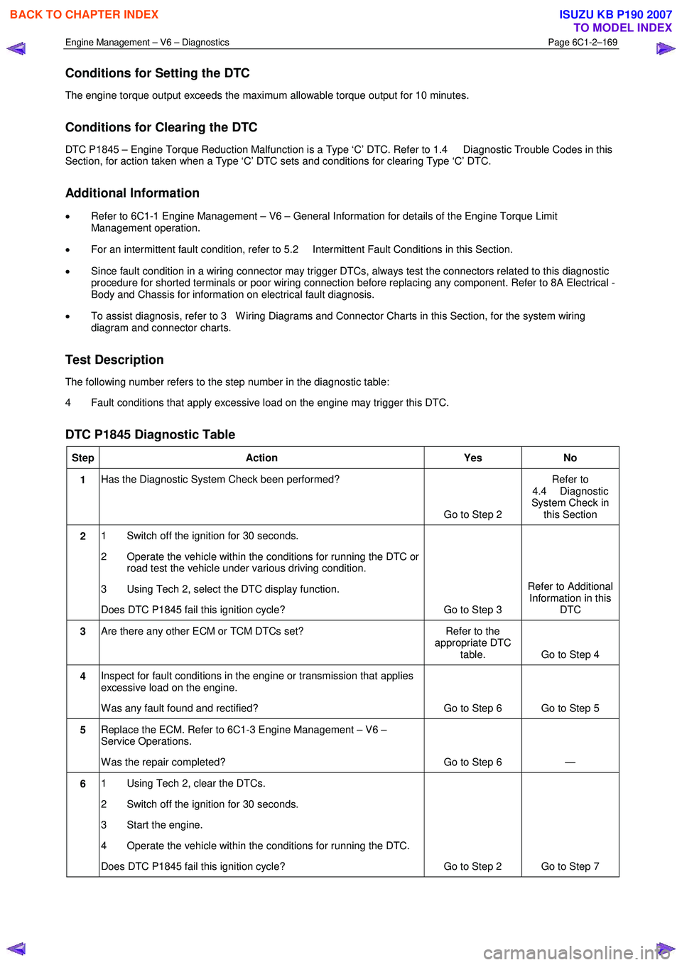
DTC P1845 Diagnostic Table
Step Action Yes No
1 Has the Diagnostic System Check been performed?
Go to Step 2 Refer to
4.4 Diagnostic
System Check in this Section
2 1 Switch off the ignition for 30 seconds.
2 Operate the vehicle within the conditions for running the DTC or road test the vehicle under various driving condition.
3 Using Tech 2, select the DTC display function.
Does DTC P1845 fail this ignition cycle? Go to Step 3 Refer to Additional
Information in this DTC
3 Are there any other ECM or TCM DTCs set? Refer to the
appropriate DTC table. Go to Step 4
4 Inspect for fault conditions in the engine or transmission that applies
excessive load on the engine.
W as any fault found and rectified? Go to Step 6 Go to Step 5
5 Replace the ECM. Refer to 6C1-3 Engine Management – V6 –
Service Operations.
W as the repair completed? Go to Step 6 —
6 1 Using Tech 2, clear the DTCs.
2 Switch off the ignition for 30 seconds.
3 Start the engine.
4 Operate the vehicle within the conditions for running the DTC.
Does DTC P1845 fail this ignition cycle? Go to Step 2 Go to Step 7
BACK TO CHAPTER INDEX
TO MODEL INDEX
ISUZU KB P190 2007
Page 3508 of 6020
Engine Management – V6 – Diagnostics Page 6C1-2–230
Vehicle Speed km/h 0 0
Engine Runtime h:m:s 00:00:00 00:10:25
Fuel Pump Relay Off / On Off On
(1) Automatic Transmission Only (2) Manual Transmission Only
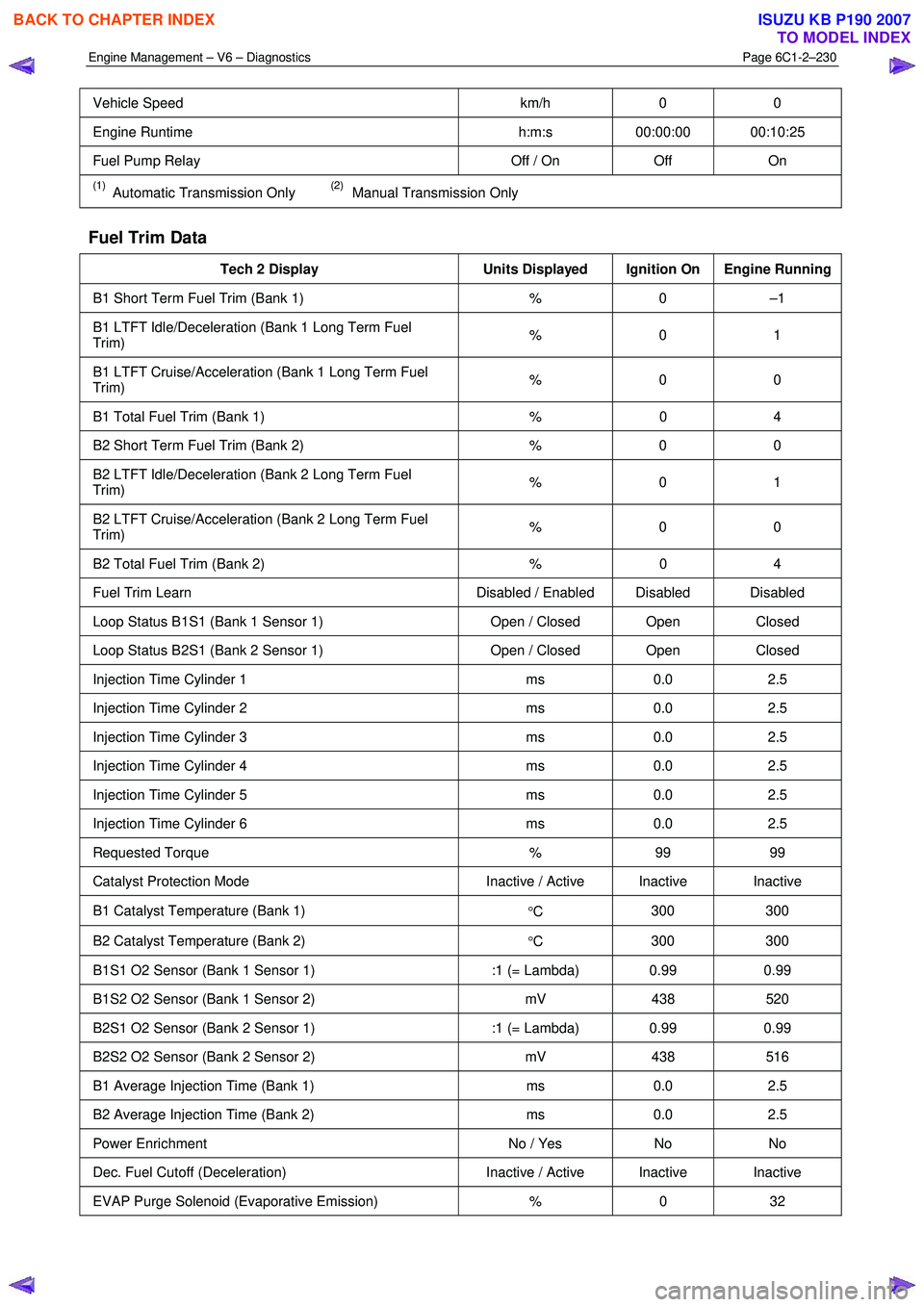
Fuel Trim Data
Tech 2 Display Units Displayed Ignition On Engine Running
B1 Short Term Fuel Trim (Bank 1) % 0 –1
B1 LTFT Idle/Deceleration (Bank 1 Long Term Fuel
Trim) % 0 1
B1 LTFT Cruise/Acceleration (Bank 1 Long Term Fuel
Trim) % 0 0
B1 Total Fuel Trim (Bank 1)
% 0 4
B2 Short Term Fuel Trim (Bank 2) % 0 0
B2 LTFT Idle/Deceleration (Bank 2 Long Term Fuel
Trim) % 0 1
B2 LTFT Cruise/Acceleration (Bank 2 Long Term Fuel
Trim) % 0 0
B2 Total Fuel Trim (Bank 2)
% 0 4
Fuel Trim Learn Disabled / Enabled Disabled Disabled
Loop Status B1S1 (Bank 1 Sensor 1) Open / Closed Open Closed
Loop Status B2S1 (Bank 2 Sensor 1) Open / Closed Open Closed
Injection Time Cylinder 1 ms 0.0 2.5
Injection Time Cylinder 2 ms 0.0 2.5
Injection Time Cylinder 3 ms 0.0 2.5
Injection Time Cylinder 4 ms 0.0 2.5
Injection Time Cylinder 5 ms 0.0 2.5
Injection Time Cylinder 6 ms 0.0 2.5
Requested Torque % 99 99
Catalyst Protection Mode Inactive / Active Inactive Inactive
B1 Catalyst Temperature (Bank 1)
°C 300 300
B2 Catalyst Temperature (Bank 2)
°C 300 300
B1S1 O2 Sensor (Bank 1 Sensor 1)
:1 (= Lambda) 0.99 0.99
B1S2 O2 Sensor (Bank 1 Sensor 2) mV 438 520
B2S1 O2 Sensor (Bank 2 Sensor 1) :1 (= Lambda) 0.99 0.99
B2S2 O2 Sensor (Bank 2 Sensor 2) mV 438 516
B1 Average Injection Time (Bank 1) ms 0.0 2.5
B2 Average Injection Time (Bank 2) ms 0.0 2.5
Power Enrichment No / Yes No No
Dec. Fuel Cutoff (Deceleration) Inactive / Active Inactive Inactive
EVAP Purge Solenoid (Evaporative Emission) % 0 32
BACK TO CHAPTER INDEX
TO MODEL INDEX
ISUZU KB P190 2007
Page 3517 of 6020
Engine Management – V6 – Diagnostics Page 6C1-2–239
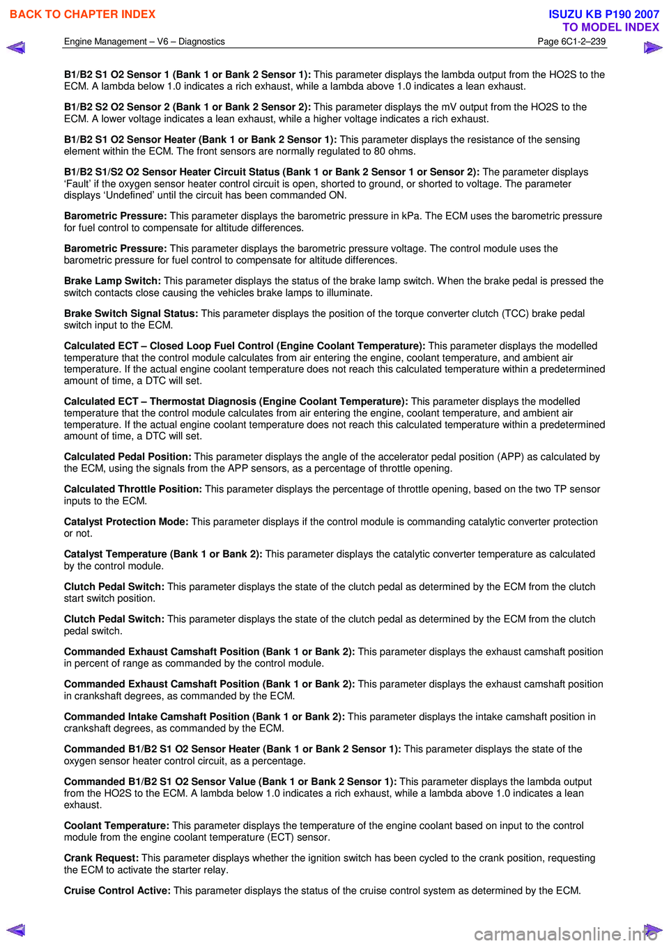
B1/B2 S1 O2 Sensor 1 (Bank 1 or Bank 2 Sensor 1): This parameter displays the lambda output from the HO2S to the
ECM. A lambda below 1.0 indicates a rich exhaust, while a lambda above 1.0 indicates a lean exhaust.
B1/B2 S2 O2 Sensor 2 (Bank 1 or Bank 2 Sensor 2): This parameter displays the mV output from the HO2S to the
ECM. A lower voltage indicates a lean exhaust, while a higher voltage indicates a rich exhaust.
B1/B2 S1 O2 Sensor Heater (Bank 1 or Bank 2 Sensor 1): This parameter displays the resistance of the sensing
element within the ECM. The front sensors are normally regulated to 80 ohms.
B1/B2 S1/S2 O2 Sensor Heater Circuit Status (Bank 1 or Bank 2 Sensor 1 or Sensor 2): The parameter displays
‘Fault’ if the oxygen sensor heater control circuit is open, shorted to ground, or shorted to voltage. The parameter
displays ‘Undefined’ until the circuit has been commanded ON.
Barometric Pressure: This parameter displays the barometric pressure in kPa. The ECM uses the barometric pressure
for fuel control to compensate for altitude differences.
Barometric Pressure: This parameter displays the barometric pressure voltage. The control module uses the
barometric pressure for fuel control to compensate for altitude differences.
Brake Lamp Switch: This parameter displays the status of the brake lamp switch. W hen the brake pedal is pressed the
switch contacts close causing the vehicles brake lamps to illuminate.
Brake Switch Signal Status: This parameter displays the position of the torque converter clutch (TCC) brake pedal
switch input to the ECM.
Calculated ECT – Closed Loop Fuel Control (Engine Coolant Temperature): This parameter displays the modelled
temperature that the control module calculates from air entering the engine, coolant temperature, and ambient air
temperature. If the actual engine coolant temperature does not reach this calculated temperature within a predetermined
amount of time, a DTC will set.
Calculated ECT – Thermostat Diagnosis (Engine Coolant Temperature): This parameter displays the modelled
temperature that the control module calculates from air entering the engine, coolant temperature, and ambient air
temperature. If the actual engine coolant temperature does not reach this calculated temperature within a predetermined
amount of time, a DTC will set.
Calculated Pedal Position: This parameter displays the angle of the accelerator pedal position (APP) as calculated by
the ECM, using the signals from the APP sensors, as a percentage of throttle opening.
Calculated Throttle Position: This parameter displays the percentage of throttle opening, based on the two TP sensor
inputs to the ECM.
Catalyst Protection Mode: This parameter displays if the control module is commanding catalytic converter protection
or not.
Catalyst Temperature (Bank 1 or Bank 2): This parameter displays the catalytic converter temperature as calculated
by the control module.
Clutch Pedal Switch: This parameter displays the state of the clutch pedal as determined by the ECM from the clutch
start switch position.
Clutch Pedal Switch: This parameter displays the state of the clutch pedal as determined by the ECM from the clutch
pedal switch.
Commanded Exhaust Camshaft Position (Bank 1 or Bank 2): This parameter displays the exhaust camshaft position
in percent of range as commanded by the control module.
Commanded Exhaust Camshaft Position (Bank 1 or Bank 2): This parameter displays the exhaust camshaft position
in crankshaft degrees, as commanded by the ECM.
Commanded Intake Camshaft Position (Bank 1 or Bank 2): This parameter displays the intake camshaft position in
crankshaft degrees, as commanded by the ECM.
Commanded B1/B2 S1 O2 Sensor Heater (Bank 1 or Bank 2 Sensor 1): This parameter displays the state of the
oxygen sensor heater control circuit, as a percentage.
Commanded B1/B2 S1 O2 Sensor Value (Bank 1 or Bank 2 Sensor 1): This parameter displays the lambda output
from the HO2S to the ECM. A lambda below 1.0 indicates a rich exhaust, while a lambda above 1.0 indicates a lean
exhaust.
Coolant Temperature: This parameter displays the temperature of the engine coolant based on input to the control
module from the engine coolant temperature (ECT) sensor.
Crank Request: This parameter displays whether the ignition switch has been cycled to the crank position, requesting
the ECM to activate the starter relay.
Cruise Control Active: This parameter displays the status of the cruise control system as determined by the ECM.
BACK TO CHAPTER INDEX
TO MODEL INDEX
ISUZU KB P190 2007
Page 3520 of 6020
Engine Management – V6 – Diagnostics Page 6C1-2–242
Oil Temperature Sensor: This parameter displays the engine oil temperature in degrees C.
Power Enrichment: This parameter displays the status of the operating mode of the ECM used to increase fuel delivery
during certain acceleration conditions.
Reduced Engine Power: This parameter displays when the ECM is commanding reduced engine power due to a
throttle actuator control (TAC) system condition.
Requested Torque: This parameter displays the calculated amount torque requested of the ECM by the Transmission
Control Module (TCM).
Short Term Fuel Trim (Bank 1 or Bank 2): This parameter displays the short-term correction to the fuel delivery by the
ECM in response to oxygen sensor 1 or 2. If the oxygen sensor indicates a lean air/fuel mixture, the control module will
add fuel, increasing the short term fuel trim above 0. If the oxygen sensor indicates a rich air/fuel mixture, the control
module will reduce fuel decreasing the short term fuel trim below 0.
Spark Advance: This parameter displays the amount of spark advance the ECM is commanding on the ignition control
circuits. The ECM determines the desired advance.
Starter Relay: This parameter displays the Em’s commanded state of the starter motor relay control circuit.
Starter Relay Circuit Status: This parameter displays the state of the starter relay control circuit. The parameter
displays ‘Fault’ if the starter relay control circuit is open, shorted to ground, or shorted to voltage. The parameter
displays Undefined Status’ until the circuit has been determined as being ‘OK’. This parameter may not change if Tech 2
is used to command the relay control circuit ON.
Start Up ECT (Engine Coolant Temperature): This parameter displays the temperature of the engine coolant on start
up based on input to the ECM from the ECT sensor.
Start Up IAT (Intake Air Temperature): This parameter displays the temperature of the intake air at start in the air
induction system based on input to the ECM from the IAT sensor.
Time Since Engine Off: This parameter displays the amount of time (hours:minutes:seconds) that has elapsed since
the engine was last cycled OFF.
Total Fuel Trim (Bank 1 or Bank 2): This parameter displays the overall fuel trim from the idle/decel cell and the
cruise/accel cell.
Total Misfire: This parameter displays the total number of cylinder firing events that the control module detected as
misfires for the last 200 crankshaft revolution sample period.
TP Sensor 1 (Throttle Position): This parameter displays the actual voltage on the TP sensor 1 signal circuit as
measured by the ECM.
TP Sensor 1 Learned Lower Position (Throttle Position): This parameter displays the learned minimum value of TP
sensor 1 as recorded by the ECM during the last learn procedure.
TP Sensor 2 (Throttle Position): This parameter displays the actual voltage on the TP sensor 2 signal circuit as
measured by the ECM.
TP Sensor 2 Learned Lower Position (Throttle Position): This parameter displays the learned minimum value of TP
sensor 2 as recorded by the ECM during the last learn procedure.
TP Sensor 1-2 Correlation (Throttle Position): This parameter displays ‘Fault’ when the ECM detects that TP sensor 1
voltage signal is not within the correct relationship to TP sensor 2. Tech 2 displays ‘Okay’ under normal operating
conditions.
Transmission Gear: This parameter displays the position of the transmission gear selector that is transmitted over the
serial data circuit from the TCM.
Transmission Gear Selector Signal: This parameter displays the position of the transmission gear selector that is
transmitted over the serial data circuit from the TCM.
Vehicle Speed: This parameter displays the speed of the vehicle as calculated by the TCM from information received
from the vehicle speed sensor (VSS).
Volumetric Efficiency: This parameter displays the volumetric efficiency of the engine as calculated by the control
module.
8.5 OBD Data
Typical Values Tech 2 Display Units Displayed
Ignition On Engine Running
B1S1 O2 Sensor (Bank 1 Sensor 1) mA 0.008 0
BACK TO CHAPTER INDEX
TO MODEL INDEX
ISUZU KB P190 2007
Page 3527 of 6020
Engine Management – V6 – Service Operations Page 6C1-3–3
2.21 Schrader Valve – Fuel Pressure Gauge Connection Point............................................................................... 47
Remove ................................................................................................................................................................. 47
Reinstall ................................................................................................................................................................ 47
2.22 Spark Plugs .................................................................................................................... ...................................... 48
Service Precautions............................................................................................................ ................................. 48
Remove ................................................................................................................................................................. 48
Inspect .................................................................................................................................................................. 48
Spark Plug Inspection .......................................................................................................... ............................... 49
Poor Spark Plug Performance.................................................................................................... ...................... 49
Analysis of Spark Plug Condition ..................................................................................................................... 51
Reinstall ................................................................................................................................................................ 53
2.23 Throttle Body Assembly......................................................................................................... ............................. 53
Handling Precautions .......................................................................................................................................... 53
Remove ................................................................................................................................................................. 53
Inspect .................................................................................................................................................................. 55
Reinstall ................................................................................................................................................................ 55
3 Specifications ................................................................................................................. ......................57
4 Assembly Lubricants ............................................................................................................ ...............60
5 Torque Specifications ..........................................................................................................................61
6 Special Tools ........................................................................................................................................62
BACK TO CHAPTER INDEX
TO MODEL INDEX
ISUZU KB P190 2007
Page 3529 of 6020
Engine Management – V6 – Service Operations Page 6C1-3–5
• Ensure the correct procedure for disconnecting and connecting engine management system wiring connectors is
always followed.
• Ensure that all wiring connectors are fitted correctly.
• The engine management system wiring connectors are designed to fit only one way; there are indexing tabs and
slots on both halves of the connector. Forcing the connector into place is not necessary if it is being installed with
the correct orientation. Failure to take care to match the indexing tabs and slots correctly can cause damage to the
connector, the module, or other vehicle components or systems.
• Never touch the connector pins of any electronic component, such as an ECM, as electrostatic discharge (ESD)
damage may result.
• W hen steam or pressure cleaning engines, do not direct the cleaning nozzle at engine management system
components.
• Never subject the ECM to temperatures less than -40 ° C and greater than 125 ° C.
• Prior to disconnection or removal of any components associated with the fuel system, clean the area around any
connection points to avoid possible contamination of the fuel system.
• A depressurised fuel system contains fuel in the fuel system and fuel lines that can be spilled during service
operations. To reduce the chance of personal injury, cover the fittings with a shop towel to absorb any fuel spillage
prior to performing the service operation. Once the service operation has been completed, place the towel in an
approved container for disposal.
• To avoid accidental fuel discharge, it is advisable to disconnect the battery and remove the fuel pump relay if the
fuel line between the fuel pump and the fuel rail is to be disconnected / open for an indefinite period.
• Always tighten fasteners to the correct tightening torque, and where indicated in the service procedure, follow the
correct tightening sequence, precautions and recommendations to prevent premature failure of the fastener or
component.
• After removing components, such as the upper or lower intake manifold, front engine pipe, heated oxygen sensor,
etc. always plug any openings to prevent dirt and other contaminants from entering.
• Do not use silicone based assembly lubricants as damage to the heated oxygen sensors may result.
Use of incorrect electrical test equipment
when performing engine management service
procedures could result in incorrect results or
component damage.
• Use only the test equipment specified in the diagnostic tables. Use of other test equipment may either give
incorrect results or damage serviceable components, refer to, 6C1-2 Engine Management – V6 – Diagnostics.
• After completing the required service operations, road test the vehicle to ensure correct engine management
system operation.
Service Requirements
Basic Knowledge Required
A lack of basic understanding of electronics,
electrical wiring circuits and use of electrical
circuit testing tools when performing certain
service procedures could result in incorrect
results or damage to components.
In addition, a general understanding of the engine management system and its component operation is essential to
prevent misdiagnosis and component damage.
BACK TO CHAPTER INDEX
TO MODEL INDEX
ISUZU KB P190 2007
Page 3533 of 6020
Engine Management – V6 – Service Operations Page 6C1-3–9
2 General Service Operations
2.1 Accelerator Pedal Position Sensor
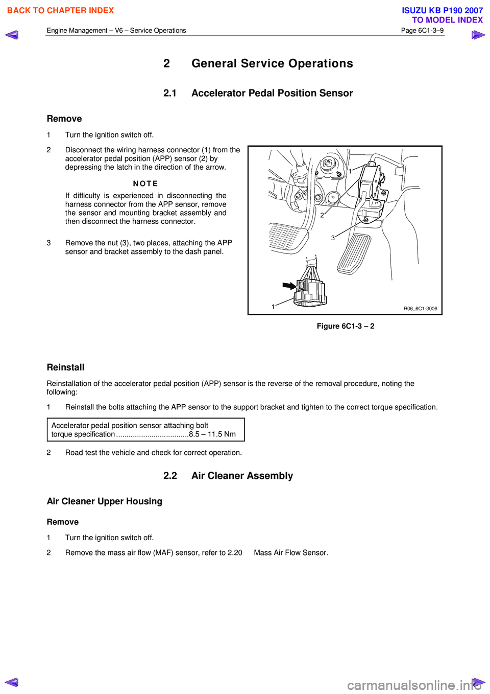
Remove
1 Turn the ignition switch off.
2 Disconnect the wiring harness connector (1) from the accelerator pedal position (APP) sensor (2) by
depressing the latch in the direction of the arrow.
NOTE
If difficulty is experienced in disconnecting the
harness connector from the APP sensor, remove
the sensor and mounting bracket assembly and
then disconnect the harness connector.
3 Remove the nut (3), two places, attaching the APP sensor and bracket assembly to the dash panel.
Figure 6C1-3 – 2
Reinstall
Reinstallation of the accelerator pedal position (APP) sensor is the reverse of the removal procedure, noting the
following:
1 Reinstall the bolts attaching the APP sensor to the support bracket and tighten to the correct torque specification.
Accelerator pedal position sensor attaching bolt
torque specification ...................................8.5 – 11.5 Nm
2 Road test the vehicle and check for correct operation.
2.2 Air Cleaner Assembly
Air Cleaner Upper Housing
Remove
1 Turn the ignition switch off.
2 Remove the mass air flow (MAF) sensor, refer to 2.20 Mass Air Flow Sensor.
BACK TO CHAPTER INDEX
TO MODEL INDEX
ISUZU KB P190 2007