2007 ISUZU KB P190 torque
[x] Cancel search: torquePage 3257 of 6020
Engine Management – V6 – General Information Page 6C1-1–15
W hen the cruise control ON-OFF switch, located on the right hand side of the dash panel, is pressed, the PIM, on
receiving the input from the switch, turns on the cruise ON-OFF switch warning lamp to inform the user that the cruise
control has been engaged.
W hen the cruise control switch assembly is pressed to SET/COAST, the PIM on receiving the input, sends a signal via
the serial data bus to the ECM. Providing the pre-conditions for cruise control operation have been met, the ECM
activates cruise control and commands the PIM to turn on the instrument cluster cruise set warning lamp, to inform the
user that cruise control is active. The ECM receives all the various inputs required to maintain the correct speed and then
controls the throttle plate depending on the load on the engine (ascending or descending hills, etc).
The cruise control is deactivated by either pressing the brake pedal, clutch pedal, cruise CANCEL or by the cruise control
ON-OFF button. In each of these instances, the ECM receives an input when any of these switches are activated. For
further information on the cruise control system, refer to 8C Cruise Control – HFV6.
3.7 Brake Torque Management
Brake torque management places limits on engine torque when the brakes are applied, regardless of the accelerator
pedal position (APP). The conditions under which brake torque management occur are as follows:
• The accelerator has been depressed before the brakes are applied,
• The brakes are applied and the ECM receives an input from the stop lamp switch,
• Vehicle speed is greater than 5 km/h,
• Engine speed is greater than 1200 rpm and
• Conditions exist for greater than 2.5 seconds.
W hen brake torque management has been implemented, the torque is reduced by altering the throttle plate opening by
25%. The ECM will monitor the rate at which the vehicle is slowing and adjust the throttle plate opening accordingly.
3.8 Emission Control Systems
Evaporative Emission Control System
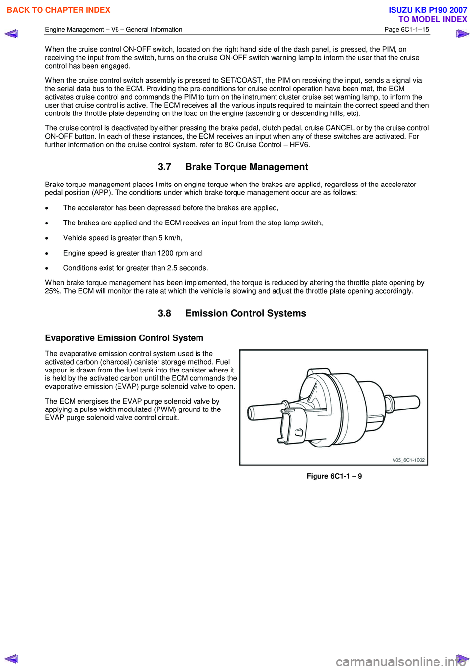
The evaporative emission control system used is the
activated carbon (charcoal) canister storage method. Fuel
vapour is drawn from the fuel tank into the canister where it
is held by the activated carbon until the ECM commands the
evaporative emission (EVAP) purge solenoid valve to open.
The ECM energises the EVAP purge solenoid valve by
applying a pulse width modulated (PW M) ground to the
EVAP purge solenoid valve control circuit.
Figure 6C1-1 – 9
BACK TO CHAPTER INDEX
TO MODEL INDEX
ISUZU KB P190 2007
Page 3261 of 6020
Engine Management – V6 – General Information Page 6C1-1–19
4 Component Description and
Operation
4.1 A/C Refrigerant Pressure Sensor
The engine control module (ECM) applies a positive 5 V reference voltage and ground to the air-conditioner (A/C)
refrigerant pressure sensor. The A/C refrigerant pressure sensor provides signal voltage to the ECM that is proportional
to the A/C refrigerant pressure. The ECM monitors the A/C refrigerant pressure sensor signal voltage to determine the
refrigerant pressure.
• The A/C refrigerant pressure sensor voltage increases as the refrigerant pressure increases.
• W hen the ECM detects the refrigerant pressure exceeds a predetermined value, the ECM activates the cooling
fans to reduce the refrigerant pressure.
• W hen the ECM detects the refrigerant pressure is too high or too low, the ECM disables the A/C clutch to protect
the A/C compressor from damage.
4.2 Brake Pedal Switch Assembly
Stop Lamp and Initial Brake Apply Switch
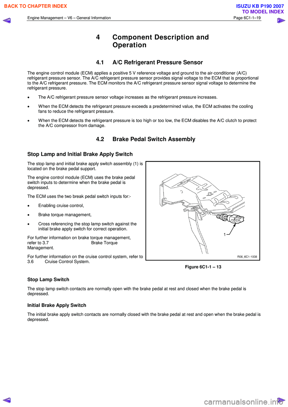
The stop lamp and initial brake apply switch assembly (1) is
located on the brake pedal support.
The engine control module (ECM) uses the brake pedal
switch inputs to determine when the brake pedal is
depressed.
The ECM uses the two break pedal switch inputs for:-
• Enabling cruise control,
• Brake torque management,
• Cross referencing the stop lamp switch against the
initial brake apply switch for correct operation.
For further information on brake torque management,
refer to 3.7 Brake Torque
Management.
For further information on the cruise control system, refer to
3.6 Cruise Control System.
Figure 6C1-1 – 13
Stop Lamp Switch
The stop lamp switch contacts are normally open with the brake pedal at rest and closed when the brake pedal is
depressed.
Initial Brake Apply Switch
The initial brake apply switch contacts are normally closed with the brake pedal at rest and open when the brake pedal is
depressed.
BACK TO CHAPTER INDEX
TO MODEL INDEX
ISUZU KB P190 2007
Page 3298 of 6020
Engine Management – V6 – Diagnostics Page 6C1-2–20
• Ensure the resistance between the ECM housing and the battery negative cable is less than 0.5 Ω.
• Check the ECM bracket fasteners for correct torque value.
• Check all engine management related components for correct installation.
• Inspect the vacuum hoses for splits, kinks, oil contamination and proper connections, refer to the vehicle emission
control information label. Check the hoses thoroughly for any type of leak or restriction.
• Inspect the air intake ducts for being collapsed, split or for having damaged areas.
• Inspect for air leaks at the throttle body mounting area, mass air flow (MAF) sensor, intake manifold and intake
manifold sealing surfaces.
• Check for wiring harness routing that may be positioned too close to a high voltage or high current device such as
the following:
− Secondary ignition components, and
− Motors and generators.
NOTE
High voltage or high current devices may induce
electrical noise on a circuit, which can interfere
with normal circuit operation.
4.4 Diagnostic System Check
Description
The engine management diagnostic procedure is organised in a logical structure that begins with the Diagnostic System
Check. The Diagnostic System Check directs the diagnostic procedure to the logical steps necessary to diagnose an
engine driveability fault condition.
Test Description
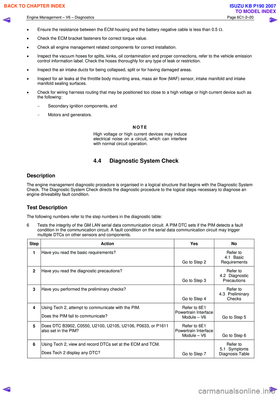
The following numbers refer to the step numbers in the diagnostic table:
6 Tests the integrity of the GM LAN serial data communication circuit. A PIM DTC sets if the PIM detects a fault condition in the communication circuit. A fault condition on the serial data communication circuit may trigger
multiple DTCs on other sensors and components.
Step Action Yes No
1 Have you read the basic requirements?
Go to Step 2 Refer to
4.1 Basic
Requirements
2 Have you read the diagnostic precautions?
Go to Step 3 Refer to
4.2 Diagnostic Precautions
3 Have you performed the preliminary checks?
Go to Step 4 Refer to
4.3 Preliminary Checks
4 Using Tech 2, attempt to communicate with the PIM.
Does the PIM fail to communicate? Refer to 6E1
Powertrain Interface Module – V6 Go to Step 5
5 Does DTC B3902, C0550, U2100, U2105, U2106, P0633, or P1611
also set in the PIM? Refer to 6E1
Powertrain Interface Module – V6 Go to Step 6
6 Using Tech 2, view and record DTCs set at the ECM and TCM.
Does Tech 2 display any DTC? Go to Step 7 Refer to
5.1 Symptoms
Diagnosis Table
BACK TO CHAPTER INDEX
TO MODEL INDEX
ISUZU KB P190 2007
Page 3303 of 6020
Engine Management – V6 – Diagnostics Page 6C1-2–25
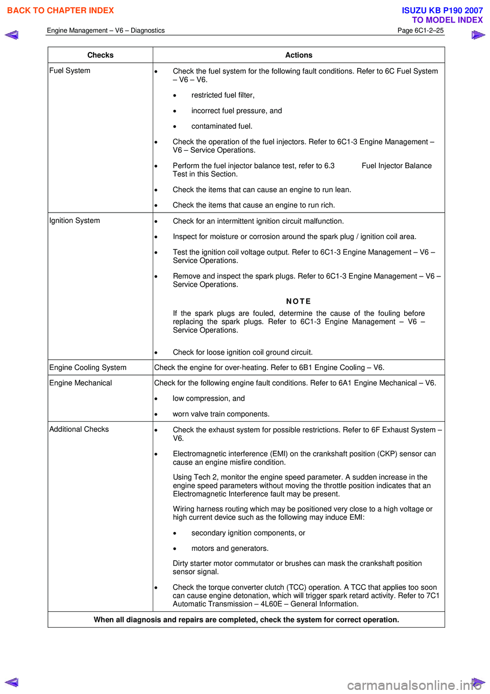
Checks Actions
Fuel System
• Check the fuel system for the following fault conditions. Refer to 6C Fuel System
– V6 – V6.
• restricted fuel filter,
• incorrect fuel pressure, and
• contaminated fuel.
• Check the operation of the fuel injectors. Refer to 6C1-3 Engine Management –
V6 – Service Operations.
• Perform the fuel injector balance test, refer to 6.3 Fuel Injector Balance
Test in this Section.
• Check the items that can cause an engine to run lean.
• Check the items that cause an engine to run rich.
Ignition System
• Check for an intermittent ignition circuit malfunction.
• Inspect for moisture or corrosion around the spark plug / ignition coil area.
• Test the ignition coil voltage output. Refer to 6C1-3 Engine Management – V6 –
Service Operations.
• Remove and inspect the spark plugs. Refer to 6C1-3 Engine Management – V6 –
Service Operations.
NOTE
If the spark plugs are fouled, determine the cause of the fouling before
replacing the spark plugs. Refer to 6C1-3 Engine Management – V6 –
Service Operations.
• Check for loose ignition coil ground circuit.
Engine Cooling System Check the engine for over-heating. Refer to 6B1 Engine Cooling – V6.
Engine Mechanical Check for the following engine fault conditions. Refer to 6A1 Engine Mechanical – V6.
• low compression, and
• worn valve train components.
Additional Checks
• Check the exhaust system for possible restrictions. Refer to 6F Exhaust System –
V6.
• Electromagnetic interference (EMI) on the crankshaft position (CKP) sensor can
cause an engine misfire condition.
Using Tech 2, monitor the engine speed parameter. A sudden increase in the engine speed parameters without moving the throttle position indicates that an
Electromagnetic Interference fault may be present.
W iring harness routing which may be positioned very close to a high voltage or high current device such as the following may induce EMI:
• secondary ignition components, or
• motors and generators.
Dirty starter motor commutator or brushes can mask the crankshaft position sensor signal.
• Check the torque converter clutch (TCC) operation. A TCC that applies too soon
can cause engine detonation, which will trigger spark retard activity. Refer to 7C1
Automatic Transmission – 4L60E – General Information.
When all diagnosis and repairs are completed, check the system for correct operation.
BACK TO CHAPTER INDEX
TO MODEL INDEX
ISUZU KB P190 2007
Page 3306 of 6020
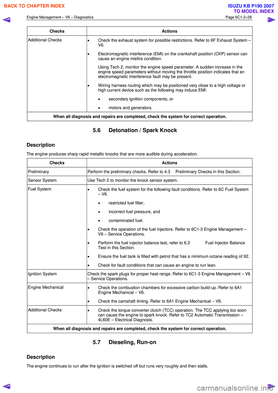
Engine Management – V6 – Diagnostics Page 6C1-2–28
Checks Actions
Additional Checks
• Check the exhaust system for possible restrictions. Refer to 6F Exhaust System –
V6.
• Electromagnetic interference (EMI) on the crankshaft position (CKP) sensor can
cause an engine misfire condition.
Using Tech 2, monitor the engine speed parameter. A sudden increase in the engine speed parameters without moving the throttle position indicates that an
electromagnetic interference fault may be present.
• W iring harness routing which may be positioned very close to a high voltage or
high current device such as the following may induce EMI:
• secondary ignition components, or
• motors and generators.
When all diagnosis and repairs are completed, check the system for correct operation.
5.6 Detonation / Spark Knock
Description
The engine produces sharp rapid metallic knocks that are more audible during acceleration.
Checks Actions
Preliminary Perform the preliminary checks. Refer to 4.3 Preliminary Checks in this Section.
Sensor System Use Tech 2 to monitor the knock sensor system.
Fuel System
• Check the fuel system for the following fault conditions. Refer to 6C Fuel System
– V6.
• restricted fuel filter,
• incorrect fuel pressure, and
• contaminated fuel.
• Check the operation of the fuel injectors. Refer to 6C1-3 Engine Management –
V6 – Service Operations.
• Perform the fuel injector balance test, refer to 6.3 Fuel Injector Balance
Test in this Section.
• Ensure the fuel tank is filled with petrol that has a minimum octane reading of 92.
• Check for fault conditions that can cause an engine to run lean.
Ignition System Check the spark plugs for proper heat range. Refer to 6C1-3 Engine Management – V6
– Service Operations.
Engine Mechanical • Check the combustion chambers for excessive carbon build-up. Refer to 6A1
Engine Mechanical – V6.
• Check the camshaft timing. Refer to 6A1 Engine Mechanical – V6.
Additional Checks
• Check the torque converter clutch (TCC) operation. The TCC applying too soon
can cause the engine to spark knock. Refer to 7C2 Automatic Transmission –
4L60E – Electrical Diagnosis.
When all diagnosis and repairs are completed, check the system for correct operation.
5.7 Dieseling, Run-on
Description
The engine continues to run after the ignition is switched off but runs very roughly and then stalls.
BACK TO CHAPTER INDEX
TO MODEL INDEX
ISUZU KB P190 2007
Page 3312 of 6020
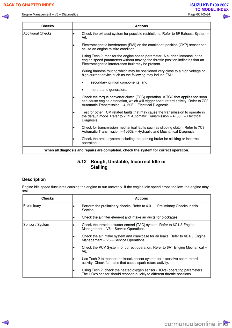
Engine Management – V6 – Diagnostics Page 6C1-2–34
Checks Actions
Additional Checks
• Check the exhaust system for possible restrictions. Refer to 6F Exhaust System –
V6.
• Electromagnetic interference (EMI) on the crankshaft position (CKP) sensor can
cause an engine misfire condition.
Using Tech 2, monitor the engine speed parameter. A sudden increase in the engine speed parameters without moving the throttle position indicates that an
Electromagnetic Interference fault may be present.
W iring harness routing which may be positioned very close to a high voltage or high current device such as the following may induce EMI:
• secondary ignition components, and
• motors and generators.
• Check the torque converter clutch (TCC) operation. A TCC that applies too soon
can cause engine detonation, which will trigger spark retard activity. Refer to 7C2
Automatic Transmission – 4L60E – Electrical Diagnosis.
• Test for other TCM related faults that may cause the transmission to operate in
the default mode. Refer to 7C2 Automatic Transmission – 4L60E – Electrical
Diagnosis.
• Check for transmission mechanical faults such as slipping clutch. Refer to 7C3
Automatic Transmission – 4L60E – Hydraulic and Mechanical Diagnosis.
• Check the brake system including the parking brake for sticking or incorrect
operation.
When all diagnosis and repairs are completed, check the system for correct operation.
5.12 Rough, Unstable, Incorrect Idle or
Stalling
Description
Engine idle speed fluctuates causing the engine to run unevenly. If the engine idle speed drops too low, the engine may
stall.
Checks Actions
Preliminary • Perform the preliminary checks. Refer to 4.3 Preliminary Checks in this
Section.
• Check the air filter element and intake air ducts for blockages.
Sensor / System
• Check the throttle actuator control (TAC) system. Refer to 6C1-3 Engine
Management – V6 – Service Operations.
• Check the air intake system and crankcase for air leaks. Refer to 6C1-3 Engine
Management – V6 – Service Operations.
• Check the PCV System for correct operation. Refer to 6A1 Engine Mechanical –
V6.
• Use Tech 2 to monitor the knock sensor system for excessive spark retard
activity. Check for items that cause spark retard activity.
• Using Tech 2, check the heated oxygen sensor (HO2s) operating parameters.
The HO2s sensor should respond quickly to different throttle positions.
BACK TO CHAPTER INDEX
TO MODEL INDEX
ISUZU KB P190 2007
Page 3314 of 6020
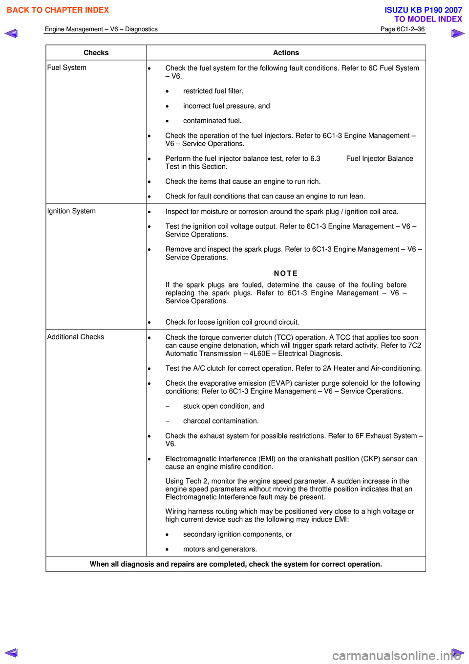
Engine Management – V6 – Diagnostics Page 6C1-2–36
Checks Actions
Fuel System
• Check the fuel system for the following fault conditions. Refer to 6C Fuel System
– V6.
• restricted fuel filter,
• incorrect fuel pressure, and
• contaminated fuel.
• Check the operation of the fuel injectors. Refer to 6C1-3 Engine Management –
V6 – Service Operations.
• Perform the fuel injector balance test, refer to 6.3 Fuel Injector Balance
Test in this Section.
• Check the items that cause an engine to run rich.
• Check for fault conditions that can cause an engine to run lean.
Ignition System
• Inspect for moisture or corrosion around the spark plug / ignition coil area.
• Test the ignition coil voltage output. Refer to 6C1-3 Engine Management – V6 –
Service Operations.
• Remove and inspect the spark plugs. Refer to 6C1-3 Engine Management – V6 –
Service Operations.
NOTE
If the spark plugs are fouled, determine the cause of the fouling before
replacing the spark plugs. Refer to 6C1-3 Engine Management – V6 –
Service Operations.
• Check for loose ignition coil ground circuit.
Additional Checks
• Check the torque converter clutch (TCC) operation. A TCC that applies too soon
can cause engine detonation, which will trigger spark retard activity. Refer to 7C2
Automatic Transmission – 4L60E – Electrical Diagnosis.
• Test the A/C clutch for correct operation. Refer to 2A Heater and Air-conditioning.
• Check the evaporative emission (EVAP) canister purge solenoid for the following
conditions: Refer to 6C1-3 Engine Management – V6 – Service Operations.
− stuck open condition, and
− charcoal contamination.
• Check the exhaust system for possible restrictions. Refer to 6F Exhaust System –
V6.
• Electromagnetic interference (EMI) on the crankshaft position (CKP) sensor can
cause an engine misfire condition.
Using Tech 2, monitor the engine speed parameter. A sudden increase in the engine speed parameters without moving the throttle position indicates that an
Electromagnetic Interference fault may be present.
W iring harness routing which may be positioned very close to a high voltage or high current device such as the following may induce EMI:
• secondary ignition components, or
• motors and generators.
When all diagnosis and repairs are completed, check the system for correct operation.
BACK TO CHAPTER INDEX
TO MODEL INDEX
ISUZU KB P190 2007
Page 3323 of 6020
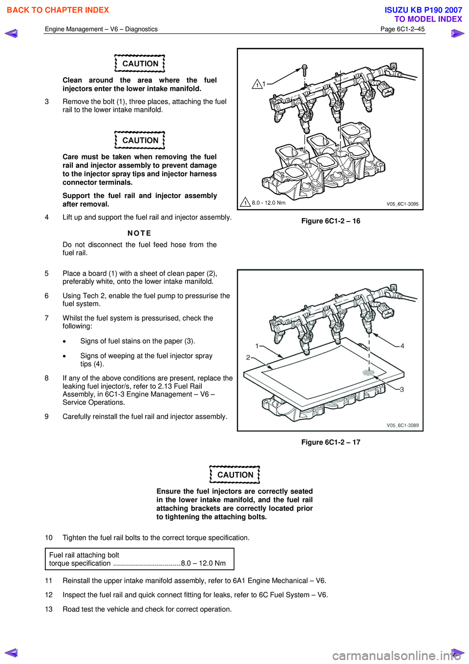
Engine Management – V6 – Diagnostics Page 6C1-2–45
Clean around the area where the fuel
injectors enter the lower intake manifold.
3 Remove the bolt (1), three places, attaching the fuel rail to the lower intake manifold.
Care must be taken when removing the fuel
rail and injector assembly to prevent damage
to the injector spray tips and injector harness
connector terminals.
Support the fuel rail and injector assembly
after removal.
4 Lift up and support the fuel rail and injector assembly.
NOTE
Do not disconnect the fuel feed hose from the
fuel rail.
Figure 6C1-2 – 16
5 Place a board (1) with a sheet of clean paper (2), preferably white, onto the lower intake manifold.
6 Using Tech 2, enable the fuel pump to pressurise the fuel system.
7 W hilst the fuel system is pressurised, check the following:
• Signs of fuel stains on the paper (3).
• Signs of weeping at the fuel injector spray
tips (4).
8 If any of the above conditions are present, replace the leaking fuel injector/s, refer to 2.13 Fuel Rail
Assembly, in 6C1-3 Engine Management – V6 –
Service Operations.
9 Carefully reinstall the fuel rail and injector assembly.
Figure 6C1-2 – 17
Ensure the fuel injectors are correctly seated
in the lower intake manifold, and the fuel rail
attaching brackets are correctly located prior
to tightening the attaching bolts.
10 Tighten the fuel rail bolts to the correct torque specification. Fuel rail attaching bolt
torque specification ..................................8.0 – 12.0 Nm
11 Reinstall the upper intake manifold assembly, refer to 6A1 Engine Mechanical – V6.
12 Inspect the fuel rail and quick connect fitting for leaks, refer to 6C Fuel System – V6.
13 Road test the vehicle and check for correct operation.
BACK TO CHAPTER INDEX
TO MODEL INDEX
ISUZU KB P190 2007