2007 ISUZU KB P190 wheel bolt torque
[x] Cancel search: wheel bolt torquePage 2819 of 6020
Engine Mechanical – V6 Page 6A1–42
Page 6A1–42
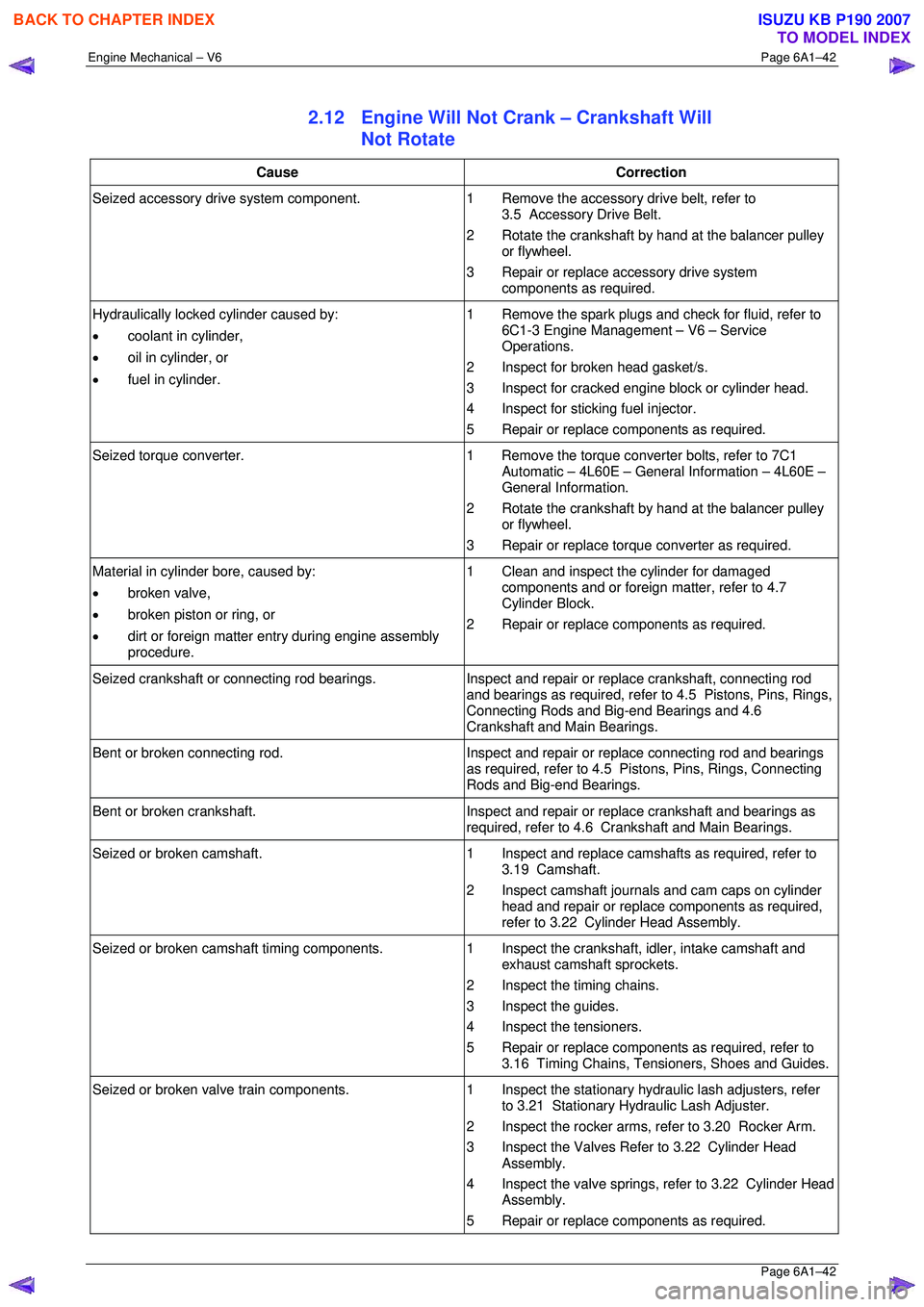
2.12 Engine Will Not Crank – Crankshaft Will
Not Rotate
Cause Correction
Seized accessory drive system component. 1 Remove the accessory drive belt, refer to
3.5 Accessory Drive Belt.
2 Rotate the crankshaft by hand at the balancer pulley or flywheel.
3 Repair or replace accessory drive system components as required.
Hydraulically locked cylinder caused by:
• coolant in cylinder,
• oil in cylinder, or
• fuel in cylinder. 1 Remove the spark plugs and check for fluid, refer to
6C1-3 Engine Management – V6 – Service
Operations.
2 Inspect for broken head gasket/s.
3 Inspect for cracked engine block or cylinder head.
4 Inspect for sticking fuel injector.
5 Repair or replace components as required.
Seized torque converter. 1 Remove the torque converter bolts, refer to 7C1
Automatic – 4L60E – General Information – 4L60E –
General Information.
2 Rotate the crankshaft by hand at the balancer pulley or flywheel.
3 Repair or replace torque converter as required.
Material in cylinder bore, caused by:
• broken valve,
• broken piston or ring, or
• dirt or foreign matter entry during engine assembly
procedure. 1 Clean and inspect the cylinder for damaged
components and or foreign matter, refer to 4.7
Cylinder Block.
2 Repair or replace components as required.
Seized crankshaft or connecting rod bearings. Inspect and repair or replace crankshaft, connecting rod
and bearings as required, refer to 4.5 Pistons, Pins, Rings,
Connecting Rods and Big-end Bearings and 4.6
Crankshaft and Main Bearings.
Bent or broken connecting rod. Inspect and repair or replace connecting rod and bearings
as required, refer to 4.5 Pistons, Pins, Rings, Connecting
Rods and Big-end Bearings.
Bent or broken crankshaft. Inspect and repair or replace crankshaft and bearings as
required, refer to 4.6 Crankshaft and Main Bearings.
Seized or broken camshaft. 1 Inspect and replace camshafts as required, refer to
3.19 Camshaft.
2 Inspect camshaft journals and cam caps on cylinder head and repair or replace components as required,
refer to 3.22 Cylinder Head Assembly.
Seized or broken camshaft timing components. 1 Inspect the crankshaft, idler, intake camshaft and
exhaust camshaft sprockets.
2 Inspect the timing chains.
3 Inspect the guides.
4 Inspect the tensioners.
5 Repair or replace components as required, refer to 3.16 Timing Chains, Tensioners, Shoes and Guides.
Seized or broken valve train components. 1 Inspect the stationary hydraulic lash adjusters, refer
to 3.21 Stationary Hydraulic Lash Adjuster.
2 Inspect the rocker arms, re fer to 3.20 Rocker Arm.
3 Inspect the Valves Refer to 3.22 Cylinder Head Assembly.
4 Inspect the valve springs, refer to 3.22 Cylinder Head Assembly.
5 Repair or replace components as required.
BACK TO CHAPTER INDEX
TO MODEL INDEX
ISUZU KB P190 2007
Page 3224 of 6020
Fuel System – V6 Page 6C – 22
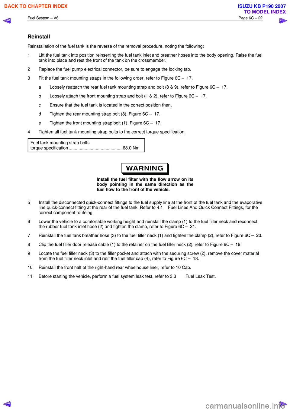
Reinstall
Reinstallation of the fuel tank is the reverse of the removal procedure, noting the following:
1 Lift the fuel tank into position reinserting the fuel tank inlet and breather hoses into the body opening. Raise the fuel tank into place and rest the front of the tank on the crossmember.
2 Replace the fuel pump electrical connector, be sure to engage the locking tab.
3 Fit the fuel tank mounting straps in the following order, refer to Figure 6C – 17, a Loosely reattach the rear fuel tank mounting strap and bolt (8 & 9), refer to Figure 6C – 17.
b Loosely attach the front mounting strap and bolt (1 & 2), refer to Figure 6C – 17.
c Ensure that the fuel tank is located in the correct position then,
d Tighten the rear mounting strap bolt (8), Figure 6C – 17.
e Tighten the front mounting strap bolt (1), Figure 6C – 17.
4 Tighten all fuel tank mounting strap bolts to the correct torque specification.
Fuel tank mounting strap bolts
torque specification ............................................68.0 Nm
Install the fuel filter with the flow arrow on its
body pointing in the same direction as the
fuel flow to the front of the vehicle.
5 Install the disconnected quick-connect fittings to the fuel supply line at the front of the fuel tank and the evaporative line quick-connect fitting at the rear of the fuel tank. Refer to 4.1 Fuel Lines And Quick Connect Fittings, for the
correct component routeing.
6 Lower the vehicle to a comfortable working height and reinstall the clamp (1) to the fuel filler neck and reconnect the rubber fuel tank inlet hose (2) and tighten the clamp, refer to Figure 6C – 21.
7 Reinstall the fuel tank breather hose (3) to the fuel filler neck (1) and tighten the clamp (2), refer to Figure 6C – 20.
8 Clip the fuel filler door release cable (1) to the retainer on the fuel filler neck (2), refer to Figure 6C – 19.
9 Locate the fuel filler neck (3) to the filler pocket and attach with the securing screw (2), remove the cover material from the fuel filler neck inlet and refit the fuel filler cap (4), refer to Figure 6C – 18.
10 Reinstall the front half of the right-hand rear wheelhouse liner, refer to 10 Cab.
11 Before starting the vehicle, perform a fuel system leak test, refer to 3.3 Fuel Leak Test.
BACK TO CHAPTER INDEX
TO MODEL INDEX
ISUZU KB P190 2007
Page 3395 of 6020
Engine Management – V6 – Diagnostics Page 6C1-2–117
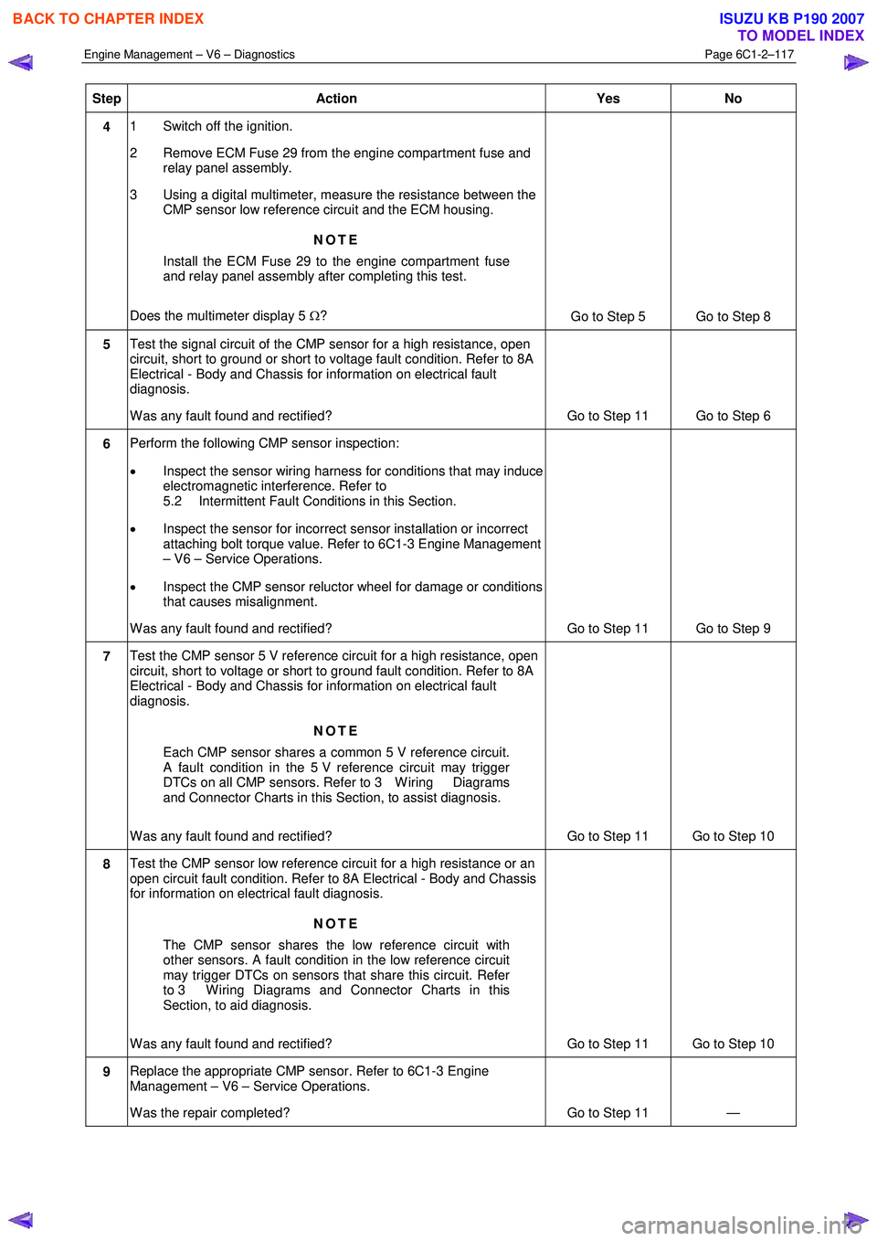
Step Action Yes No
4 1 Switch off the ignition.
2 Remove ECM Fuse 29 from the engine compartment fuse and relay panel assembly.
3 Using a digital multimeter, measure the resistance between the CMP sensor low reference circuit and the ECM housing.
NOTE
Install the ECM Fuse 29 to the engine compartment fuse
and relay panel assembly after completing this test.
Does the multimeter display 5 Ω?
Go to Step 5 Go to Step 8
5 Test the signal circuit of the CMP sensor for a high resistance, open
circuit, short to ground or short to voltage fault condition. Refer to 8A
Electrical - Body and Chassis for information on electrical fault
diagnosis.
W as any fault found and rectified? Go to Step 11 Go to Step 6
6 Perform the following CMP sensor inspection:
• Inspect the sensor wiring harness for conditions that may induce
electromagnetic interference. Refer to
5.2 Intermittent Fault Conditions in this Section.
• Inspect the sensor for incorrect sensor installation or incorrect
attaching bolt torque value. Refer to 6C1-3 Engine Management
– V6 – Service Operations.
• Inspect the CMP sensor reluctor wheel for damage or conditions
that causes misalignment.
W as any fault found and rectified? Go to Step 11 Go to Step 9
7 Test the CMP sensor 5 V reference circuit for a high resistance, open
circuit, short to voltage or short to ground fault condition. Refer to 8A
Electrical - Body and Chassis for information on electrical fault
diagnosis.
NOTE
Each CMP sensor shares a common 5 V reference circuit.
A fault condition in the 5 V reference circuit may trigger
DTCs on all CMP sensors. Refer to 3 W iring Diagrams
and Connector Charts in this Section, to assist diagnosis.
W as any fault found and rectified? Go to Step 11 Go to Step 10
8 Test the CMP sensor low reference circuit for a high resistance or an
open circuit fault condition. Refer to 8A Electrical - Body and Chassis
for information on electrical fault diagnosis.
NOTE
The CMP sensor shares the low reference circuit with
other sensors. A fault condition in the low reference circuit
may trigger DTCs on sensors that share this circuit. Refer
to 3 W iring Diagrams and Connector Charts in this
Section, to aid diagnosis.
W as any fault found and rectified? Go to Step 11 Go to Step 10
9 Replace the appropriate CMP sensor. Refer to 6C1-3 Engine
Management – V6 – Service Operations.
W as the repair completed? Go to Step 11 —
BACK TO CHAPTER INDEX
TO MODEL INDEX
ISUZU KB P190 2007
Page 3410 of 6020
Engine Management – V6 – Diagnostics Page 6C1-2–132
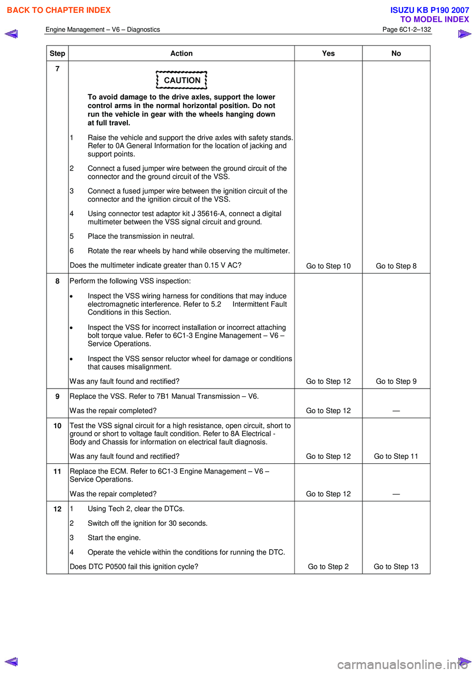
Step Action Yes No
7
To avoid damage to the drive axles, support the lower
control arms in the normal horizontal position. Do not
run the vehicle in gear with the wheels hanging down
at full travel.
1 Raise the vehicle and support the drive axles with safety stands. Refer to 0A General Information for the location of jacking and
support points.
2 Connect a fused jumper wire between the ground circuit of the connector and the ground circuit of the VSS.
3 Connect a fused jumper wire between the ignition circuit of the connector and the ignition circuit of the VSS.
4 Using connector test adaptor kit J 35616-A, connect a digital multimeter between the VSS signal circuit and ground.
5 Place the transmission in neutral.
6 Rotate the rear wheels by hand while observing the multimeter.
Does the multimeter indicate greater than 0.15 V AC? Go to Step 10 Go to Step 8
8 Perform the following VSS inspection:
• Inspect the VSS wiring harness for conditions that may induce
electromagnetic interference. Refer to 5.2 Intermittent Fault
Conditions in this Section.
• Inspect the VSS for incorrect installation or incorrect attaching
bolt torque value. Refer to 6C1-3 Engine Management – V6 –
Service Operations.
• Inspect the VSS sensor reluctor wheel for damage or conditions
that causes misalignment.
W as any fault found and rectified? Go to Step 12 Go to Step 9
9 Replace the VSS. Refer to 7B1 Manual Transmission – V6.
W as the repair completed? Go to Step 12 —
10 Test the VSS signal circuit for a high resistance, open circuit, short to
ground or short to voltage fault condition. Refer to 8A Electrical -
Body and Chassis for information on electrical fault diagnosis.
W as any fault found and rectified? Go to Step 12 Go to Step 11
11 Replace the ECM. Refer to 6C1-3 Engine Management – V6 –
Service Operations.
W as the repair completed? Go to Step 12 —
12 1 Using Tech 2, clear the DTCs.
2 Switch off the ignition for 30 seconds.
3 Start the engine.
4 Operate the vehicle within the conditions for running the DTC.
Does DTC P0500 fail this ignition cycle? Go to Step 2 Go to Step 13
BACK TO CHAPTER INDEX
TO MODEL INDEX
ISUZU KB P190 2007
Page 3715 of 6020
Powertrain Interface Module – V6 Page 6E1–54
• For an intermittent fault condition, refer to Intermittent Fault Conditions in this Section.
• The VSS in conjunction with the 40X reluctor wheel generates an AC signal voltage. The amplitude and frequency
of the signal generated is proportional to the vehicle speed. The PIM uses this signal from the VSS signal circuit to
determine the vehicle speed.
• Since fault condition in a wiring connector may trigger DTCs, always test the connectors related to this diagnostic
procedure for shorted terminals or poor wiring connection before replacing any component. Refer to 8A Electrical -
Body and Chassis for information on electrical fault diagnosis.
• To assist diagnosis, refer to 6 W iring Diagram and Connector Chart in this Section, for the system wiring diagram
and connector charts.
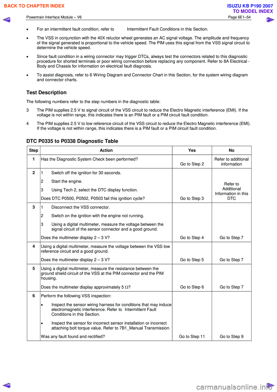
Test Description
The following numbers refer to the step numbers in the diagnostic table:
3 The PIM supplies 2.5 V to signal circuit of the VSS circuit to reduce the Electro Magnetic interference (EMI). If the voltage is not within range, this indicates there is an PIM fault or a PIM circuit fault condition.
4 The PIM supplies 2.5 V to low reference circuit of the VSS circuit to reduce the Electro Magnetic interference (EMI). If the voltage is not within range, this indicates there is a PIM fault or a PIM circuit fault condition.
DTC P0335 to P0338 Diagnostic Table
Step Action Yes No
1
Has the Diagnostic System Check been performed?
Go to Step 2 Refer to additional
information
2 1 Switch off the ignition for 30 seconds.
2 Start the engine.
3 Using Tech 2, select the DTC display function.
Does DTC P0500, P0502, P0503 fail this ignition cycle? Go to Step 3 Refer to
Additional
Information in this DTC
3 1 Disconnect the VSS connector.
2 Switch on the ignition with the engine not running.
3 Using a digital multimeter, measure the voltage between the signal circuit of the sensor connector and a good ground.
Does the multimeter display 2 – 3 V? Go to Step 4 Go to Step 7
4 Using a digital multimeter, measure the voltage between the VSS low
reference circuit and a good ground.
Does the multimeter display 2 – 3 V? Go to Step 5 Go to Step 7
5 Using a digital multimeter, measure the resistance between the
ground shield circuit of the VSS at the PIM connector and the PIM
housing.
Does the multimeter display approximately 5 Ω? Go to Step 6 Go to Step 7
6
Perform the following VSS inspection:
• Inspect the sensor wiring harness for conditions that may induce
electromagnetic interference. Refer to Intermittent Fault
Conditions in this Section.
• Inspect the sensor for incorrect sensor installation or incorrect
attaching bolt torque value. Refer to 7B1_Manual Transmission.
W as any fault found and rectified? Go to Step 11 Go to Step 9
BACK TO CHAPTER INDEX
TO MODEL INDEX
ISUZU KB P190 2007
Page 3773 of 6020
Automatic Transmission – 4L60E – General Information Page 7C1–13
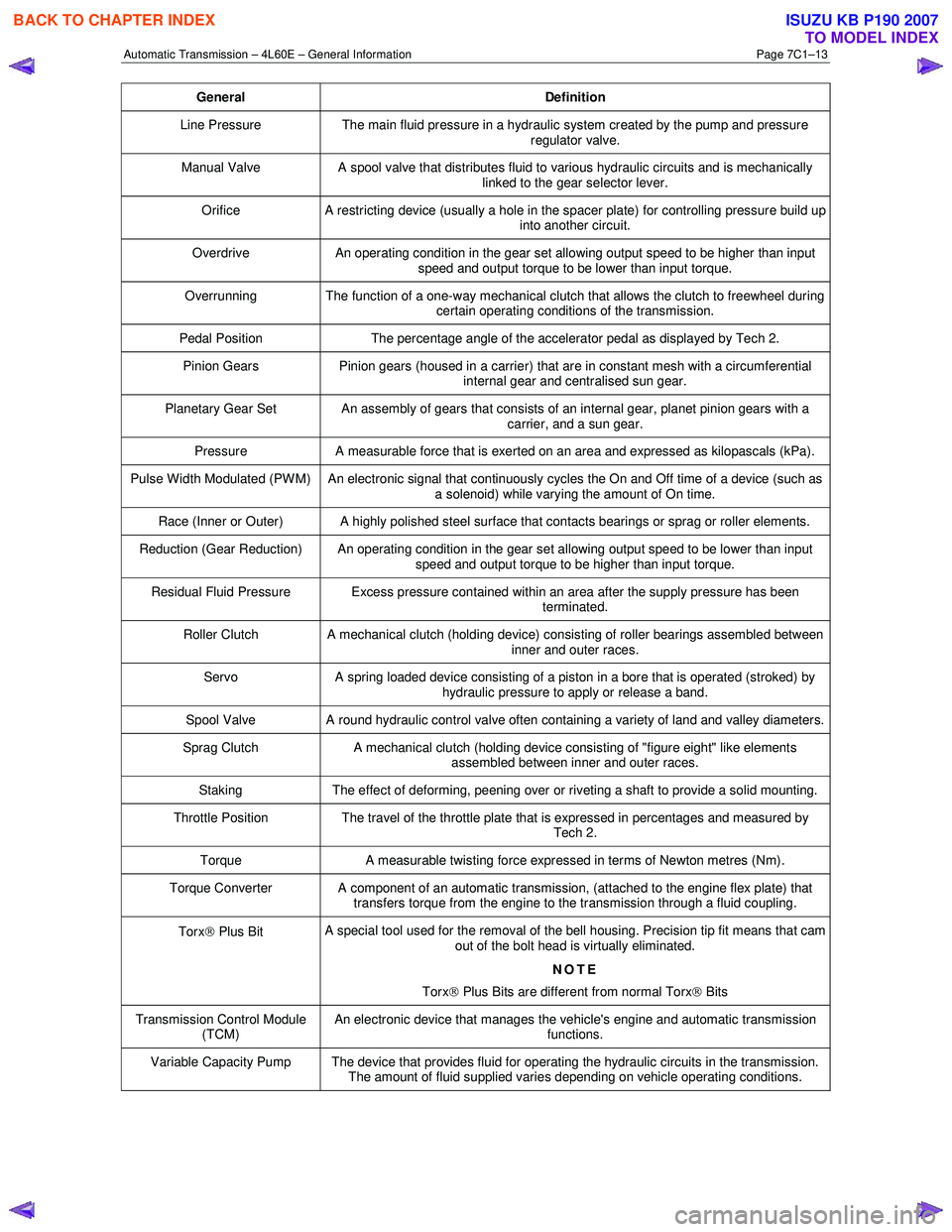
General Definition
Line Pressure The main fluid pressure in a hydraulic system created by the pump and pressure
regulator valve.
Manual Valve A spool valve that distributes fluid to various hydraulic circuits and is mechanically
linked to the gear selector lever.
Orifice A restricting device (usually a hole in the spacer plate) for controlling pressure build up
into another circuit.
Overdrive An operating condition in the gear set allowing output speed to be higher than input
speed and output torque to be lower than input torque.
Overrunning The function of a one-way mechanical clutch that allows the clutch to freewheel during certain operating conditions of the transmission.
Pedal Position The percentage angle of the accelerator pedal as displayed by Tech 2.
Pinion Gears Pinion gears (housed in a carrier) that are in constant mesh with a circumferential
internal gear and centralised sun gear.
Planetary Gear Set An assembly of gears that consists of an internal gear, planet pinion gears with a carrier, and a sun gear.
Pressure A measurable force that is exerted on an area and expressed as kilopascals (kPa).
Pulse Width Modulated (PW M) An electronic signal that continuously cycles the On and Off time of a device (such as
a solenoid) while varying the amount of On time.
Race (Inner or Outer) A highly polished steel surface that contacts bearings or sprag or roller elements.
Reduction (Gear Reduction) An operating condition in the gear set allowing output speed to be lower than input speed and output torque to be higher than input torque.
Residual Fluid Pressure Excess pressure contained within an area after the supply pressure has been terminated.
Roller Clutch A mechanical clutch (holding device) consisting of roller bearings assembled between inner and outer races.
Servo A spring loaded device consisting of a piston in a bore that is operated (stroked) by
hydraulic pressure to apply or release a band.
Spool Valve A round hydraulic control valve often containing a variety of land and valley diameters.
Sprag Clutch A mechanical clutch (holding device consisting of "figure eight" like elements
assembled between inner and outer races.
Staking The effect of deforming, peening over or riveting a shaft to provide a solid mounting.
Throttle Position The travel of the throttle plate that is expressed in percentages and measured by
Tech 2.
Torque A measurable twisting force expressed in terms of Newton metres (Nm).
Torque Converter A component of an automatic transmission, (attached to the engine flex plate) that
transfers torque from the engine to the transmission through a fluid coupling.
Torx Plus Bit A special tool used for the removal of the bell housing. Precision tip fit means that cam
out of the bolt head is virtually eliminated.
NOTE
Torx
Plus Bits are different from normal Torx
Bits
Transmission Control Module
(TCM) An electronic device that manages the vehicle's engine and automatic transmission
functions.
Variable Capacity Pump The device that provides fluid for operating the hydraulic circuits in the transmission. The amount of fluid supplied varies depending on vehicle operating conditions.
BACK TO CHAPTER INDEX
TO MODEL INDEX
ISUZU KB P190 2007
Page 3931 of 6020
Automatic Transmission – 4L60E – On-vehicle Servicing Page 7C4–18
Ensure the four wheels are off the ground
before performing the starting test.
4 W ith the ignition switched to the ON position, check if the engine can only be started in the Park and Neutral shift selector positions and ensure the back-up lamps illuminate when Reverse is selected. A further minor adjustment
may be required to achieve this state.
NOTE
To gain access to the rear attaching screw (11) it
will be necessary to remove the connector.
5 After the switch has been adjusted, tighten the rear attaching screw (11) to the correct torque specification. Neutral start and back-up lamp switch
attaching screw torque specification .................. 25.0 Nm
6 Reinstall the connector and the CPA securing pin.
7 Remove the switch front attaching screw (1).
8 Install the heat shield (3) and tighten the attaching screws (1 and 2) to the correct torque specification.
Heat shield front attaching screw
torque specification ............................................ 25.0 Nm
Heat shield rear attaching screw torque specification ..............................................9.0 Nm
9 Lower the vehicle to the ground and re-check the operation of the neutral start and back-up lamp switch. The vehicle must start only with the shift selector in the Park or Neutral positions and the back-up lamps should only
illuminate when Reverse is selected.
3.5 Vehicle Speed Sensor
NOTE
For the speed sensor fitted to four wheel drive
vehicles (4WD), refer to 7D Transfer Case and
Adaptor Housing.
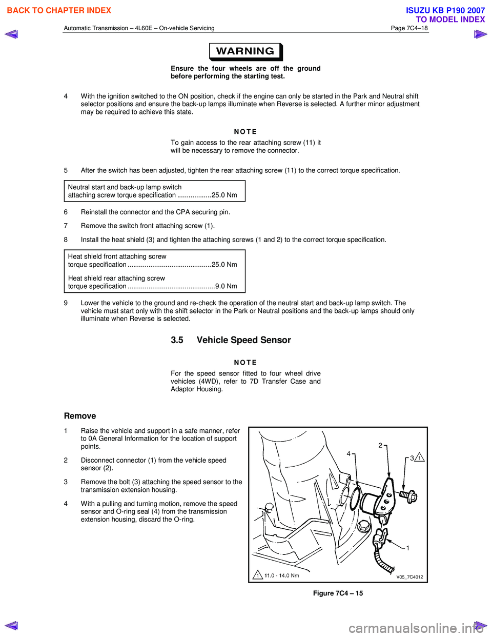
Remove
1 Raise the vehicle and support in a safe manner, refer
to 0A General Information for the location of support
points.
2 Disconnect connector (1) from the vehicle speed sensor (2).
3 Remove the bolt (3) attaching the speed sensor to the transmission extension housing.
4 With a pulling and turning motion, remove the speed sensor and O-ring seal (4) from the transmission
extension housing, discard the O-ring.
Figure 7C4 – 15
BACK TO CHAPTER INDEX
TO MODEL INDEX
ISUZU KB P190 2007
Page 3959 of 6020
Automatic Transmission – 4L60E – On-vehicle Servicing Page 7C4–46
Reinstall
1 If required on 4W D vehicle, reinstall the transfer case, refer to 7D Transfer Case and Adaptor Housing.
2 Ensure the transmission and the engine mating surfaces are clean and free of burrs.
3 Lubricate the torque converter spigot (7) with a small amount of high temperature wheel bearing grease, refer to Figure 7C4 – 62.
4 Install a new filler tube seal into the transmission case.
Support the transmission while installing the
attaching bolts to avoid damage to the torque
converter and flexplate. Do not have the
transmission hanging.
5 Bring the transmission up to the engine, inserting the filler tube and ensuring the locating dowels completely enter the torque converter housing.
6 Reconnect the breather hose to the top of the transmission case.
NOTE
The bolts attaching the torque converter housing
are facing forward except for the bolt in position ℑ
which is facing rearward.
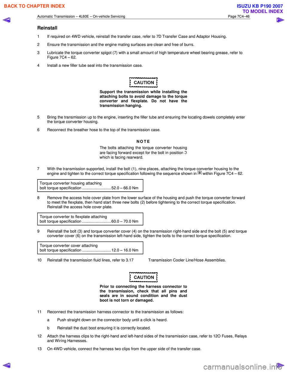
7 With the transmission supported, install the bolt (1), nine places, attaching the torque converter housing to the engine and tighten to the correct torque specification following the sequence shown in
within Figure 7C4 – 62.
Torque converter housing attaching
bolt torque specification .......................... 52.0 – 66.0 Nm
8 Remove the access hole cover plate from the lower surface of the housing and push the torque converter forward to meet the flexplate, then hand start three new bolts (2) before tightening to the correct torque specification.
Reinstall the access hole cover plate.
Torque converter to flexplate attaching
bolt torque specification .......................... 60.0 – 70.0 Nm
9 Reinstall the bolt (3) and torque converter cover (4) on the transmission right-hand side and the bolt (5) and torque converter cover (6) on the transmission left-hand side, tighten the bolts to the correct torque specification.
Torque converter cover attaching
bolt torque specification .......................... 12.0 – 16.0 Nm
10 Reinstall the transmission fluid lines, refer to 3.17 Transmission Cooler Line/Hose Assemblies.
Prior to connecting the harness connector to
the transmission, check that all pins and
seals are in sound condition and the dust
boot is not torn or damaged.
11 Reconnect the transmission harness connector to the transmission as follows: a Push straight down on the connector body until a click is heard.
b Reinstall the dust boot ensuring it is correctly located.
12 Attach the harness clips to the right-hand and left-hand sides of the transmission case, refer to 12O Fuses, Relays and Wiring Harnesses.
13 On 4WD vehicle, connect the harness two clips from the upper side of the transfer case.
BACK TO CHAPTER INDEX
TO MODEL INDEX
ISUZU KB P190 2007