2007 ISUZU KB P190 wheel bolt torque
[x] Cancel search: wheel bolt torquePage 1582 of 6020
FUEL SYSTEM (4JK1/4JJ1) 6C-41
Removal
Note: W hen repairs to the fuel system have been
completed, start the engine and check the fuel system
for loose connections or leakage. For the fuel system
diagnosis, see Section "Drivability and Emission".
1. Disconnect the battery ground cable.
2. Slowly loosen the fuel filler cap.
Note: Be careful that fuel does not spout out because o
f
change of pressure in the fuel tank.
Note: Cover opening of the filler neck to prevent an
y
dust entering. 3. Jack up the vehicle.
4. Disconnect the quick connector (5) of the fuel tube at the fuel cooler way.
5. Remove fuel return hose (8) from the pipe.
6. Remove fixing bolt (7) of the bracket fuel coole
r
and remove bracket fuel cooler (6).
Note: Cover the opening of the pipe to prevent any dust
and fuel leakage.
Note: For remove fuel cooler, Remove bolts (10) of the
fuel cooler and remove fuel cooler.
7. Support underneath of the fuel tank with a lifter.
8. Remove the inner liner of the wheel house at rea
r
left side.
9. Remove fixing bolt of the filler neck from the body.
10. Disconnect the quick connector (5) of the fuel tube from the fuel pipe and the evapo tube from evapo
joint connector.
Note: Cover the quick connector to prevent any dust
entering and prevent fuel leakage.
Note: Refer to "Fuel Tube/Quick Connector Fittings" in
this section when performing any repairs.
11. Remove fixing bolt (1) of the tank band and remove the tank band (2).
12. Disconnect the pump and sender connector on the fuel pump and remove the harness from the weld
clip on the fuel tank.
13. Lower the fuel tank (3).
Note: W hen lowering the fuel tank from the vehicle, do
not scratch the hoses and tubes by contact with othe
r
parts.
Installation
1. Raise the fuel tank.
Note: W hen raising the fuel tank to the vehicle, do not
scratch the hoses and tubes by contact with other parts.
2. Connect the pump and sender connector to the fuel pump and install the harness to the weld clip
on the tank.
Note: The connector must be securely connected
against the stopper.
3. Install the tank band and fasten bolt.
Torque: 68 N ⋅
⋅⋅
⋅
m (6.9 kg ⋅
⋅⋅
⋅
m /50 lb ft)
Note: The anchor of the tank band must be securely
installed to the guide hole on the frame.
4. Connect the quick connector of the fuel tube to the fuel pipe and the evapo tube from evapo joint
connector.
Note: Pull off the left checker on the fuel pipe.
Note: Refer to "Fuel Tube/Quick Connector Fittings" in
this section when performing any repairs.
5. Install the filler neck to the body with bolt.
Note: For install the fuel cooler to the bracket with bolt.
Torque: 6.5 N ⋅
⋅⋅
⋅
m (0.7 kg ⋅
⋅⋅
⋅
m /61 lb in)
6. Install the bracket to Frame with bolt. Torque: 48 N ⋅
⋅⋅
⋅
m (4.9 kg ⋅
⋅⋅
⋅
m /35 lb ft)
7. Install the fuel return hose at the fuel cooler way.
8. Install the quick connector at the fuel cooler way.
9. Install the inner liner of the wheel house at rear left side.
10. Remove lifter from the fuel tank.
11. Lower the vehicle.
12. Tighten the filler cap until at least three clicks.
13. Connect the battery ground cable.
BACK TO CHAPTER INDEX
TO MODEL INDEX
ISUZU KB P190 2007
Page 2060 of 6020
6A-46 ENGINE MECHANICAL (C24SE)
Inspection
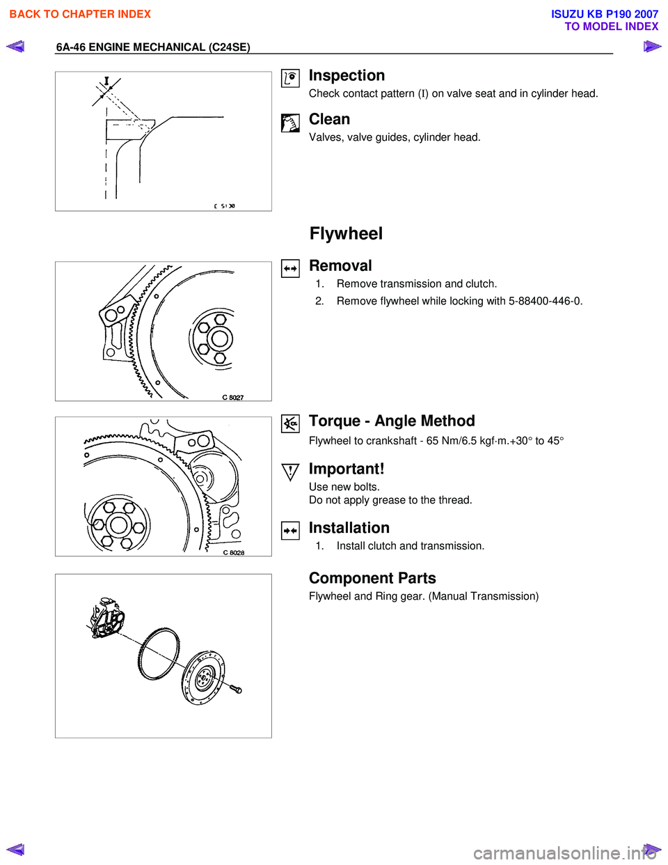
Check contact pattern ( I) on valve seat and in cylinder head.
Clean
Valves, valve guides, cylinder head.
Flywheel
Removal
1. Remove transmission and clutch.
2. Remove flywheel while locking with 5-88400-446-0.
Torque - Angle Method
Flywheel to crankshaft - 65 Nm/6.5 kgf ⋅m.+30 ° to 45 °
Important!
Use new bolts.
Do not apply grease to the thread.
Installation
1. Install clutch and transmission.
Component Parts
Flywheel and Ring gear. (Manual Transmission)
BACK TO CHAPTER INDEX
TO MODEL INDEX
ISUZU KB P190 2007
Page 2063 of 6020
ENGINE MECHANICAL (C24SE) 6A-49
Reassembly
Reassemble clutch assembly.
Disassembly
Disassemble clutch assembly to flywheel using 5-8840-2634-0
Torque Angle-Method
Clutch assembly to flywheel-17.6Nm/1.8 kgf �xm.
RTW 46ASH002801
Oil Pan and Bearing Bridge
Removal
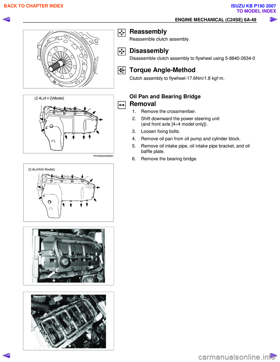
1. Remove the crossmember.
2. Shift downward the power steering unit (and front axle [4 ×4 model only]).
3. Loosen fixing bolts.
4. Remove oil pan from oil pump and cylinder block.
5. Remove oil intake pipe, oil intake pipe bracket, and oil baffle plate.
6. Remove the bearing bridge.
BACK TO CHAPTER INDEX
TO MODEL INDEX
ISUZU KB P190 2007
Page 2070 of 6020
6A-56 ENGINE MECHANICAL (C24SE)
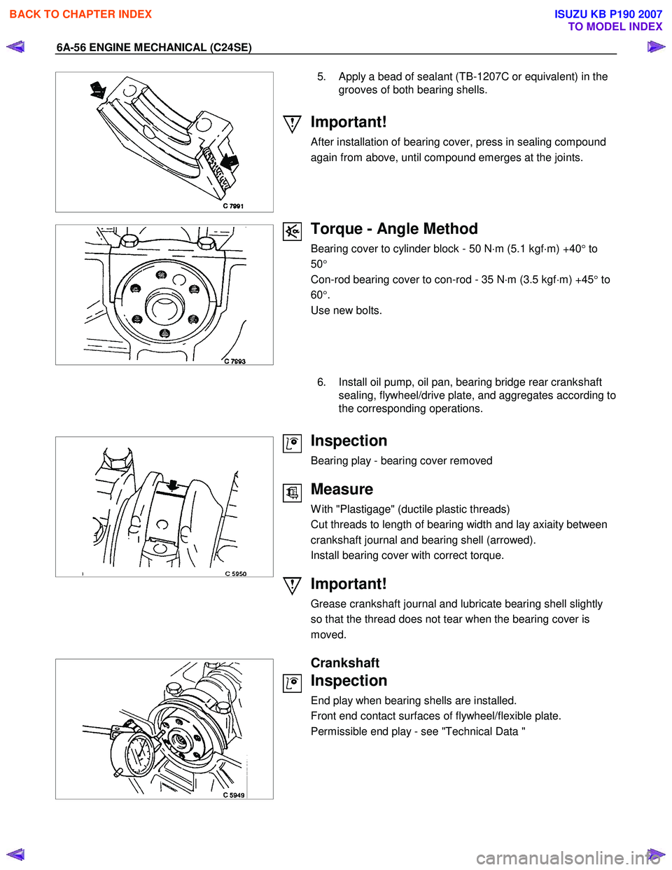
5. Apply a bead of sealant (TB-1207C or equivalent) in the grooves of both bearing shells.
Important!
After installation of bearing cover, press in sealing compound
again from above, until compound emerges at the joints.
Torque - Angle Method
Bearing cover to cylinder block - 50 N ⋅m (5.1 kgf ⋅m) +40 ° to
50 °
Con-rod bearing cover to con-rod - 35 N ⋅m (3.5 kgf ⋅m) +45 ° to
60 °.
Use new bolts.
6. Install oil pump, oil pan, bearing bridge rear crankshaft
sealing, flywheel/drive plate, and aggregates according to
the corresponding operations.
Inspection
Bearing play - bearing cover removed
Measure
W ith "Plastigage" (ductile plastic threads)
Cut threads to length of bearing width and lay axiaity between
crankshaft journal and bearing shell (arrowed).
Install bearing cover with correct torque.
Important!
Grease crankshaft journal and lubricate bearing shell slightly
so that the thread does not tear when the bearing cover is
moved.
Crankshaft
Inspection
End play when bearing shells are installed.
Front end contact surfaces of flywheel/flexible plate.
Permissible end play - see "Technical Data "
BACK TO CHAPTER INDEX
TO MODEL INDEX
ISUZU KB P190 2007
Page 2102 of 6020
6A-88 ENGINE MECHANICAL (C24SE)
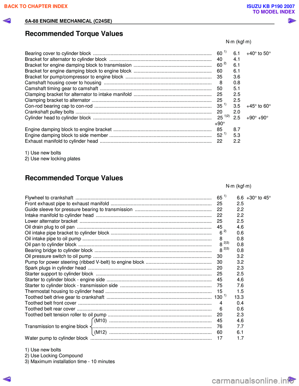
Recommended Torque Values
N⋅m (kgf ⋅m)
Bearing cover to cylinder block ........................................................................................ 60
1) 6.1 +40 ° to 50 °
Bracket for alternator to cylinder block ............................................................................ 40 4.1
Bracket for engine damping block to transmission .......................................................... 60
2) 6.1
Bracket for engine damping block to engine block .......................................................... 60 6.1
Bracket for pump/compressor to engine block ................................................................ 35 3.6
Camshaft housing cover to housing ................................................................................ 8 0.8
Camshaft timing gear to camshaft ................................................................................... 50 5.1
Clamping bracket for alternator to intake manifold .......................................................... 25 2.5
Clamping bracket to alternator ......................................................................................... 25 2.5
Con-rod bearing cap to con-rod ....................................................................................... 35
1) 3.5 +45 ° to 60 °
Crankshaft pulley bolts ..................................................................................................... 2 0 2.0
Cylinder head to cylinder block ........................................................................................ 25
1)2) 2.5 +90 ° +90 °
+90 °
Engine damping block to engine bracket ......................................................................... 85 8.7
Engine damping block to side member ............................................................................ 52
1) 5.3
Exhaust manifold to cylinder head ................................................................................... 22 2.2
1) Use new bolts
2) Use new locking plates
Recommended Torque Values
N⋅m (kgf ⋅m)
Flywheel to crankshaft ..................................................................................................... 65
1) 6.6 +30° to 45 °
Front exhaust pipe to exhaust manifold ........................................................................... 25 2.5
Guide sleeve for pressure bearing to transmission ......................................................... 22 2.2
Intake manifold to cylinder head ...................................................................................... 22 2.2
Lower alternator bracket .................................................................................................. 25 2.5
Oil drain plug to oil pan .................................................................................................... 45 4.6
Oil intake pipe bracket to cylinder block ........................................................................... 6
2) 0.6
Oil intake pipe to oil pump ................................................................................................ 8 0.8
Oil pan to cylinder block ................................................................................................... 8
2)3) 0.8
Bearing bridge to cylinder block ....................................................................................... 8 2)3) 0.8
Oil pressure switch to oil pump ........................................................................................ 30 3.2
Pump for power steering (ribbed V-belt) to engine block ................................................. 30 3.2
Spark plugs in cylinder head ............................................................................................ 20 2. 3
Starter support to cylinder block ...................................................................................... 25 2.5
Starter to cylinder block - engine side .............................................................................. 45 4.6
Starter to cylinder block - transmission side .................................................................... 75 7.6
Thermostat housing to cylinder head ............................................................................... 15 1.5
Toothed belt drive gear to crankshaft .............................................................................. 130
1) 13.3
Toothed belt front cover ................................................................................................... 4 0.4
Toothed belt rear cover .................................................................................................... 6 0.6
Toothed belt tension roller to oil pump ............................................................................. 20 2.3 (M10) ............................................................................ 45 4.6
Transmission to engine block ......................................................................................... 76 7.7 (M12) ............................................................................ 60 6.1
W ater pump to cylinder block .......................................................................................... 17 1.7
1) Use new bolts
2) Use Locking Compound
3) Maximum installation time - 10 minutes
BACK TO CHAPTER INDEX
TO MODEL INDEX
ISUZU KB P190 2007
Page 2132 of 6020
6C-14 ENGINE FUEL (C24SE)
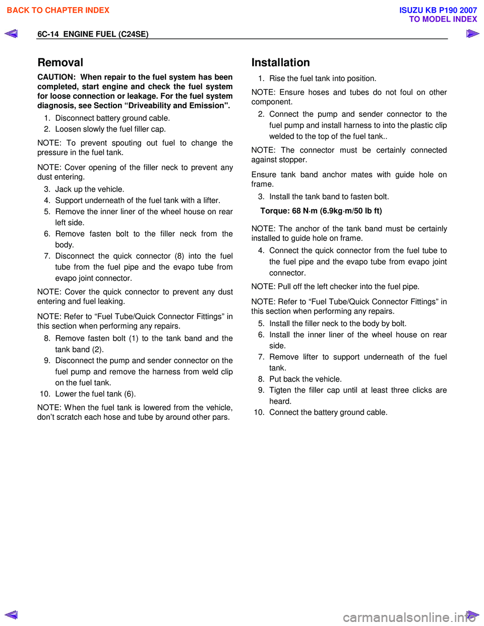
Removal
CAUTION: When repair to the fuel system has been
completed, start engine and check the fuel system
for loose connection or leakage. For the fuel system
diagnosis, see Section “Driveability and Emission".
1. Disconnect battery ground cable.
2. Loosen slowly the fuel filler cap.
NOTE: To prevent spouting out fuel to change the
pressure in the fuel tank.
NOTE: Cover opening of the filler neck to prevent an
y
dust entering.
3. Jack up the vehicle.
4. Support underneath of the fuel tank with a lifter.
5. Remove the inner liner of the wheel house on rea
r
left side.
6. Remove fasten bolt to the filler neck from the body.
7. Disconnect the quick connector (8) into the fuel
tube from the fuel pipe and the evapo tube from
evapo joint connector.
NOTE: Cover the quick connector to prevent any dust
entering and fuel leaking.
NOTE: Refer to “Fuel Tube/Quick Connector Fittings” in
this section when performing any repairs.
8. Remove fasten bolt (1) to the tank band and the tank band (2).
9. Disconnect the pump and sender connector on the
fuel pump and remove the harness from weld clip
on the fuel tank.
10. Lower the fuel tank (6).
NOTE: W hen the fuel tank is lowered from the vehicle,
don’t scratch each hose and tube by around other pars.
Installation
1. Rise the fuel tank into position.
NOTE: Ensure hoses and tubes do not foul on othe
r
component. 2. Connect the pump and sender connector to the
fuel pump and install harness to into the plastic clip
welded to the top of the fuel tank..
NOTE: The connector must be certainly connected
against stopper.
Ensure tank band anchor mates with guide hole on
frame.
3. Install the tank band to fasten bolt.
Torque: 68 N ⋅
⋅⋅
⋅
m (6.9kg ⋅
⋅⋅
⋅
m/50 lb ft)
NOTE: The anchor of the tank band must be certainl
y
installed to guide hole on frame. 4. Connect the quick connector from the fuel tube to
the fuel pipe and the evapo tube from evapo joint
connector.
NOTE: Pull off the left checker into the fuel pipe.
NOTE: Refer to “Fuel Tube/Quick Connector Fittings” in
this section when performing any repairs.
5. Install the filler neck to the body by bolt.
6. Install the inner liner of the wheel house on rea
r
side.
7. Remove lifter to support underneath of the fuel tank.
8. Put back the vehicle.
9. Tigten the filler cap until at least three clicks are
heard.
10. Connect the battery ground cable.
BACK TO CHAPTER INDEX
TO MODEL INDEX
ISUZU KB P190 2007
Page 2514 of 6020
Engine Mechanical – V6 Page 6A1–35
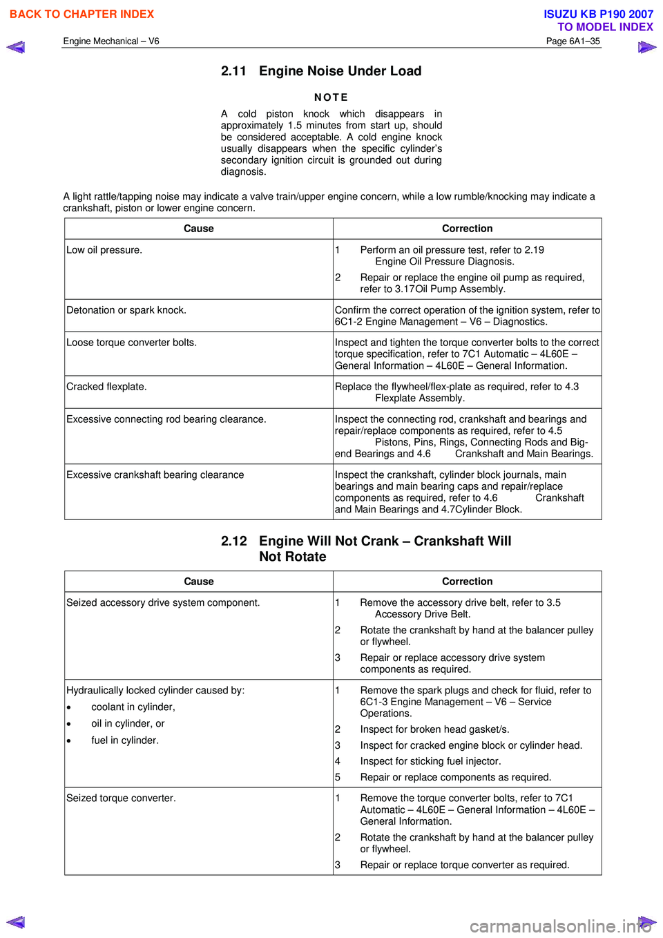
2.11 Engine Noise Under Load
NOTE
A cold piston knock which disappears in
approximately 1.5 minutes from start up, should
be considered acceptable. A cold engine knock
usually disappears when the specific cylinder’s
secondary ignition circuit is grounded out during
diagnosis.
A light rattle/tapping noise may indicate a valve train/upper engine concern, while a low rumble/knocking may indicate a
crankshaft, piston or lower engine concern.
Cause Correction
Low oil pressure. 1 Perform an oil pressure test, refer to 2.19
Engine Oil Pressure Diagnosis.
2 Repair or replace the engine oil pump as required, refer to 3.17 Oil Pump Assembly.
Detonation or spark knock. Confirm the correct operation of the ignition system, refer to
6C1-2 Engine Management – V6 – Diagnostics.
Loose torque converter bolts. Inspect and tighten the torque converter bolts to the correct
torque specification, refer to 7C1 Automatic – 4L60E –
General Information – 4L60E – General Information.
Cracked flexplate. Replace the flywheel/flex-plate as required, refer to 4.3
Flexplate Assembly.
Excessive connecting rod bearing clearance. Inspect the connecting rod, crankshaft and bearings and
repair/replace components as required, refer to 4.5
Pistons, Pins, Rings, Connecting Rods and Big-
end Bearings and 4.6 Crankshaft and Main Bearings.
Excessive crankshaft bearing clearance Inspect the crankshaft, cylinder block journals, main
bearings and main bearing caps and repair/replace
components as required, refer to 4.6 Crankshaft
and Main Bearings and 4.7Cylinder Block.
2.12 Engine Will Not Crank – Crankshaft Will Not Rotate
Cause Correction
Seized accessory drive system component. 1 Remove the accessory drive belt, refer to 3.5
Accessory Drive Belt.
2 Rotate the crankshaft by hand at the balancer pulley or flywheel.
3 Repair or replace accessory drive system components as required.
Hydraulically locked cylinder caused by:
• coolant in cylinder,
• oil in cylinder, or
• fuel in cylinder. 1 Remove the spark plugs and check for fluid, refer to
6C1-3 Engine Management – V6 – Service
Operations.
2 Inspect for broken head gasket/s.
3 Inspect for cracked engine block or cylinder head.
4 Inspect for sticking fuel injector.
5 Repair or replace components as required.
Seized torque converter. 1 Remove the torque converter bolts, refer to 7C1
Automatic – 4L60E – General Information – 4L60E –
General Information.
2 Rotate the crankshaft by hand at the balancer pulley or flywheel.
3 Repair or replace torque converter as required.
BACK TO CHAPTER INDEX
TO MODEL INDEX
ISUZU KB P190 2007
Page 2818 of 6020
Engine Mechanical – V6 Page 6A1–41
Page 6A1–41
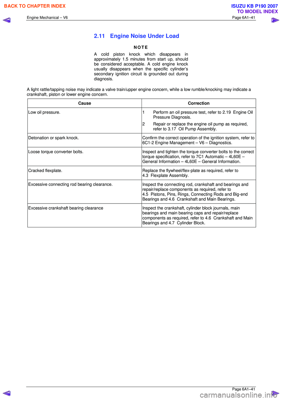
2.11 Engine Noise Under Load
NOTE
A cold piston knock which disappears in
approximately 1.5 minutes from start up, should
be considered acceptable. A cold engine knock
usually disappears when t he specific cylinder’s
secondary ignition circuit is grounded out during
diagnosis.
A light rattle/tapping noise may indicate a valve train/upper engine concern, while a low rumble/knocking may indicate a
crankshaft, piston or lower engine concern.
Cause Correction
Low oil pressure. 1 Perform an oil pressure test, refer to 2.19 Engine Oil
Pressure Diagnosis.
2 Repair or replace the engine oil pump as required, refer to 3.17 Oil Pump Assembly.
Detonation or spark knock. Confirm the correct operation of the ignition system, refer to
6C1-2 Engine Management – V6 – Diagnostics.
Loose torque converter bolts. Inspect and tighten the torque converter bolts to the correct
torque specification, refer to 7C1 Automatic – 4L60E –
General Information – 4L60E – General Information.
Cracked flexplate. Replace the flywheel/flex-plate as required, refer to
4.3 Flexplate Assembly.
Excessive connecting rod bearing clearance. Inspect the connecting rod, crankshaft and bearings and
repair/replace components as required, refer to
4.5 Pistons, Pins, Rings, Connecting Rods and Big-end
Bearings and 4.6 Crankshaft and Main Bearings.
Excessive crankshaft bearing clearance Inspect the crankshaft, cylinder block journals, main
bearings and main bearing caps and repair/replace
components as required, refer to 4.6 Crankshaft and Main
Bearings and 4.7 Cylinder Block.
BACK TO CHAPTER INDEX
TO MODEL INDEX
ISUZU KB P190 2007