2007 ISUZU KB P190 wheel bolt torque
[x] Cancel search: wheel bolt torquePage 4457 of 6020
ON-VEHICLE SERVICE (JR405E) 7A3-3
Cold Level
The vehicle must not have been driven so that the
temperature reaches around 20 °C (68 °F) before the
cold level check is made.
1. Park the vehicle on a level surface.
2. Apply the parking brake firmly.
3. Start the engine and allow it to warm up.
The engine coolant temperature gauge needle should be midway between the “C” mark and “H”
mark.
4. Let the engine run at idle.
Move the select lever slowly through all the gea
r
ranges.
Stop in each range just long enough for the transmission to engage.
5. Return the select lever either “P” or “N”.
6. Remove the ATF level dipstick.
7. W ipe the dipstick clean with a paper towel.
8. Reinsert the dipstick and wait several seconds.
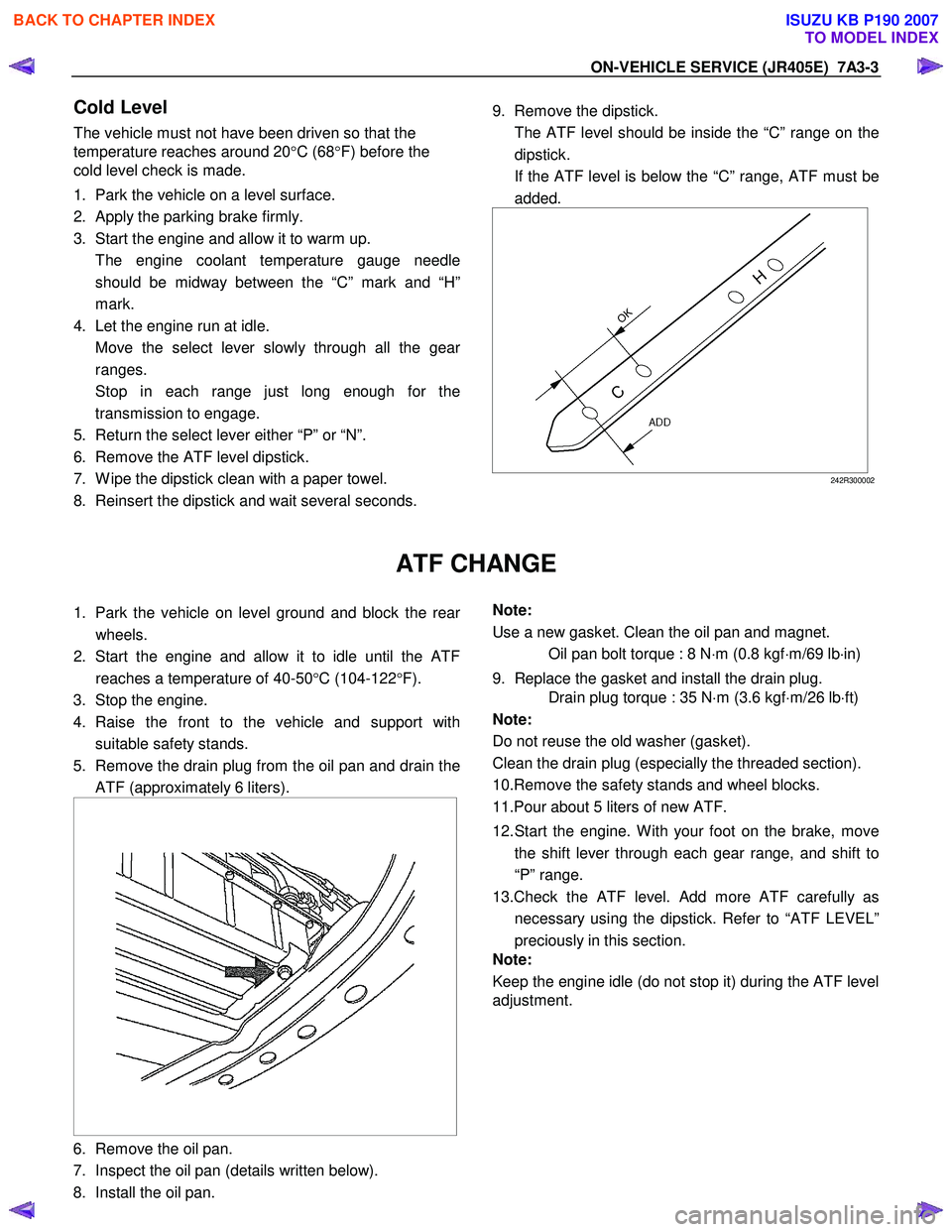
9. Remove the dipstick.
The ATF level should be inside the “C” range on the dipstick.
If the ATF level is below the “C” range, ATF must be added.
242R300002
ATF CHANGE
1. Park the vehicle on level ground and block the rear
wheels.
2. Start the engine and allow it to idle until the ATF reaches a temperature of 40-50 °C (104-122 °F).
3. Stop the engine.
4. Raise the front to the vehicle and support with suitable safety stands.
5. Remove the drain plug from the oil pan and drain the ATF (approximately 6 liters).
6. Remove the oil pan.
7. Inspect the oil pan (details written below).
8. Install the oil pan.
Note:
Use a new gasket. Clean the oil pan and magnet.
Oil pan bolt torque : 8 N ⋅m (0.8 kgf ⋅m/69 lb ⋅in)
9. Replace the gasket and install the drain plug.
Drain plug torque : 35 N ⋅m (3.6 kgf ⋅m/26 lb ⋅ft)
Note:
Do not reuse the old washer (gasket).
Clean the drain plug (especially the threaded section).
10.Remove the safety stands and wheel blocks.
11.Pour about 5 liters of new ATF.
12. Start the engine. W ith your foot on the brake, move the shift lever through each gear range, and shift to
“P” range.
13.Check the ATF level. Add more ATF carefully as necessary using the dipstick. Refer to “ATF LEVEL”
preciously in this section.
Note:
Keep the engine idle (do not stop it) during the ATF level
adjustment.
BACK TO CHAPTER INDEX
TO MODEL INDEX
ISUZU KB P190 2007
Page 4460 of 6020
7A3-6 ON-VEHICLE SERVICE (JR405E)
INHIBITOR SWITCH
The inhibitor switch is attached to the right side of the
transmission.
Inspect
1. Block the wheels.
2. Disconnect the negative battery cable.
3. Disconnect the harness connectors.
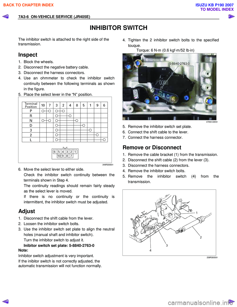
4. Use an ohmmeter to check the inhibitor switch continuity between the following terminals as shown
in the figure.
5. Place the select lever in the “N” position.
249R300001
6. Move the select lever to either side.
Check the inhibitor switch continuity between the terminals shown in Step 4.
The continuity readings should remain fairly stead
y
as the select lever is moved.
If there is no continuity or the continuity is intermittent, the inhibitor switch must be adjusted.
Adjust
1. Disconnect the shift cable from the lever.
2. Loosen the inhibitor switch bolts.
3. Use the inhibitor switch set plate to align the neutral holes (manual shaft and inhibitor switch).
Turn the inhibitor switch to adjust it.
Inibitor switch set plate: 5-8840-2763-0
Note:
Inhibitor switch adjustment is very important.
If the inibitor switch is not correctly adjusted, the
automatic transmission will not function normally.
4. Tighten the 2 inhibitor switch bolts to the specified
touque.
Torque: 6 N·m (0.6 kgf·m/52 lb·in)
47INH-SW 01
5. Remove the inhibitor switch set plate.
6. Connect the shift cable to the lever.
7. Connect the harness connector.
Remove or Disconnect
1. Remove the cable bracket (1) from the transmission.
2. Disconnect the shift cable (2) from the lever (3).
3. Disconnect the harness connectors.
4. Remove the inhibitor switch bolts.
5. Remove the inhibitor switch (4) from the transmission.
238R300001
BACK TO CHAPTER INDEX
TO MODEL INDEX
ISUZU KB P190 2007
Page 4461 of 6020
ON-VEHICLE SERVICE (JR405E) 7A3-7
Install or Connect
1. Install the inhibitor switch to the transmission.
Temporarily tighten the inhibitor switch bolts.
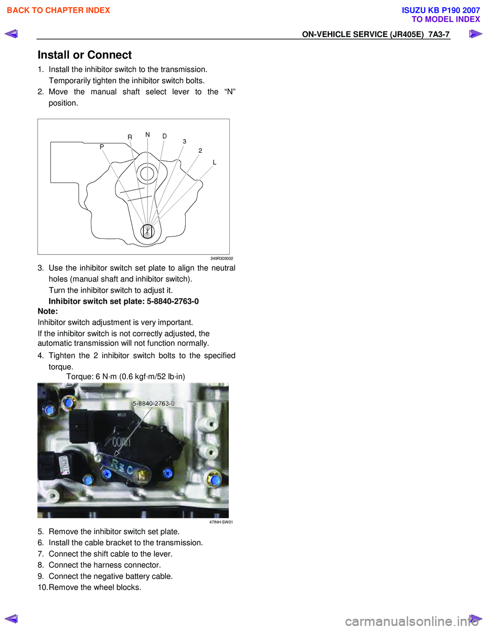
2. Move the manual shaft select lever to the “N” position.
249R300002
3. Use the inhibitor switch set plate to align the neutral
holes (manual shaft and inhibitor switch).
Turn the inhibitor switch to adjust it.
Inhibitor switch set plate: 5-8840-2763-0
Note:
Inhibitor switch adjustment is very important.
If the inhibitor switch is not correctly adjusted, the
automatic transmission will not function normally.
4. Tighten the 2 inhibitor switch bolts to the specified torque.
Torque: 6 N·m (0.6 kgf·m/52 lb·in)
47INH-SW 01
5. Remove the inhibitor switch set plate.
6. Install the cable bracket to the transmission.
7. Connect the shift cable to the lever.
8. Connect the harness connector.
9. Connect the negative battery cable.
10. Remove the wheel blocks.
BACK TO CHAPTER INDEX
TO MODEL INDEX
ISUZU KB P190 2007
Page 4471 of 6020
ON-VEHICLE SERVICE (JR405E) 7A3-17
Remove or Disconnect
1. Block the wheels.
2. Disconnect the negative battery cable.
3. Drain the fluid.
Refer to “ATF CHANGE” in this section.
4. Remove the 19 bolts and oil pan.
5. Inspect the bottom of the oil pan and strainer netting for foreign material (clutch facing and metal
shavings).
If there is an excessive accumulation of foreign material, the oil strainer must be replaced.
Further inspection is required to determine the source of the foreign material.
6. Remove the harness assembly (including the oil temperature sensor).
7. Remove the 11 bolts and the solenoid fixing plate.
8. Remove the 6 solenoids and 3 oil pressure switches.
Inspect
Oil pressure switch
Apply compressed air (390 kPa/4.0 kgf/cm2/57 psi) to
the oil pressure switch to check the oil pressure switch
continuity between the connector and screw.
Replace the oil pressure switch if the result of inspection
is abnormal.
Oil temperature sensor (harness assembly)
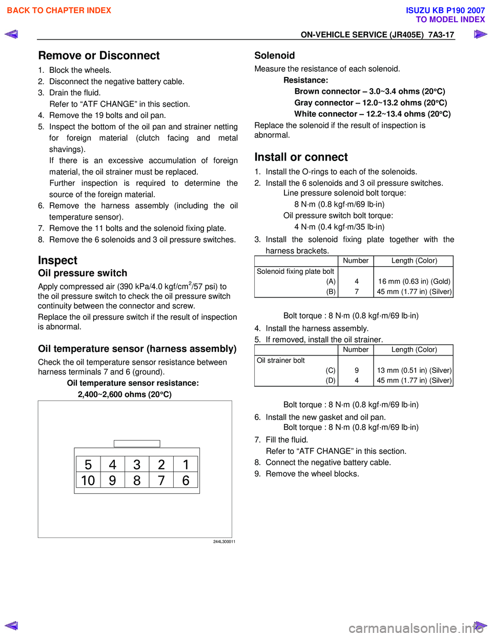
Check the oil temperature sensor resistance between
harness terminals 7 and 6 (ground).
Oil temperature sensor resistance:
2,400~2,600 ohms (20 °
°°
°
C)
244L300011
Solenoid
Measure the resistance of each solenoid.
Resistance:
Brown connector – 3.0~3.4 ohms (20 °
°°
°
C)
Gray connector – 12.0~13.2 ohms (20 °
°°
°
C)
White connector – 12.2~13.4 ohms (20 °
°°
°
C)
Replace the solenoid if the result of inspection is
abnormal.
Install or connect
1. Install the O-rings to each of the solenoids.
2. Install the 6 solenoids and 3 oil pressure switches.
Line pressure solenoid bolt torque:
8 N·m (0.8 kgf·m/69 lb·in)
Oil pressure switch bolt torque:
4 N·m (0.4 kgf·m/35 lb·in)
3. Install the solenoid fixing plate together with the harness brackets.
Number Length (Color)
Solenoid fixing plate bolt
(A)
(B)
4
7
16 mm (0.63 in) (Gold)
45 mm (1.77 in) (Silver)
Bolt torque : 8 N·m (0.8 kgf·m/69 lb·in)
4. Install the harness assembly.
5. If removed, install the oil strainer.
Number Length (Color)
Oil strainer bolt
(C)
(D)
9
4
13 mm (0.51 in) (Silver)
45 mm (1.77 in) (Silver)
Bolt torque : 8 N·m (0.8 kgf·m/69 lb·in)
6. Install the new gasket and oil pan.
Bolt torque : 8 N·m (0.8 kgf·m/69 lb·in)
7. Fill the fluid.
Refer to “ATF CHANGE” in this section.
8. Connect the negative battery cable.
9. Remove the wheel blocks.
BACK TO CHAPTER INDEX
TO MODEL INDEX
ISUZU KB P190 2007
Page 4473 of 6020
ON-VEHICLE SERVICE (JR405E) 7A3-19
Install or Connect
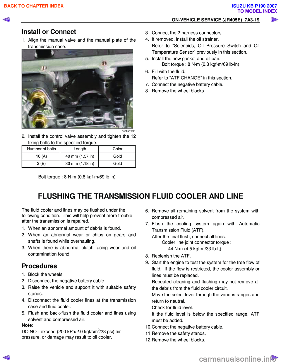
1. Align the manual valve and the manual plate of the
transmission case.
43ASSY119
2. Install the control valve assembly and tighten the 12 fixing bolts to the specified torque.
Number of bolts Length Color
10 (A) 40 mm (1.57 in) Gold
2 (B) 30 mm (1.18 in) Gold
Bolt torque : 8 N·m (0.8 kgf·m/69 lb·in)
3. Connect the 2 harness connectors.
4. If removed, install the oil strainer.
Refer to “Solenoids, Oil Pressure Switch and Oil Temperature Sensor” previously in this section.
5. Install the new gasket and oil pan.
Bolt torque : 8 N·m (0.8 kgf·m/69 lb·in)
6. Fill with the fluid.
Refer to “ATF CHANGE” in this section.
7. Connect the negative battery cable.
8. Remove the wheel blocks.
FLUSHING THE TRANSMISSION FLUID COOLER AND LINE
The fluid cooler and lines may be flushed under the
following condition. This will help prevent more trouble
after the transmission is repaired.
1. W hen an abnormal amount of debris is found.
2. W hen an abnormal wear or chips on gears and shafts is found while overhauling.
3. W hen there is abnormal clutch facing wear and oil contamination found.
Procedures
1. Block the wheels.
2. Disconnect the negative battery cable.
3. Raise the vehicle and support it with suitable safet
y
stands.
4. Disconnect the fluid cooler lines at the transmission case and fluid cooler.
5. Flush and back-flush the fluid cooler and lines using solvent and compressed air.
Note:
DO NOT exceed (200 kPa/2.0 kgf/cm
2/28 psi) air
pressure, or damage may result to oil cooler.
6. Remove all remaining solvent from the system with
compressed air.
7. Flush the cooling system again with Automatic Transmission Fluid (ATF).
After the final flush, connect all lines.
Cooler line joint connector torque :
44 N·m (4.5 kgf·m/33 lb·ft)
8. Replenish the ATF.
9. Start the engine to test the system for the free flow o
f
fluid. If the flow is restricted, the cooler assembly o
r
lines must be replaced.
Repeated cleaning and flushing may not remove all the debris from the fluid cooler circuit.
Move the select lever through the various ranges and return to neutral.
Check for fluid level.
If the fluid level is below the specified range, ATF must be added.
10. Connect the negative battery cable.
11. Remove the safety stands.
12. Remove the wheel blocks.
BACK TO CHAPTER INDEX
TO MODEL INDEX
ISUZU KB P190 2007
Page 4476 of 6020
7A3-22 ON-VEHICLE SERVICE (JR405E)
4. Install the transmission mount.
Bolt torque (rubber to transmission) :
50N·m (5.1 kgf·m/37 lb·ft)
Nut torque (rubber to crossmember) :
52N·m (5.3 kgf·m/38 lb·ft)
5. Install the 3rd crossmember.
Bolt and Nut torque : 67 N·m (6.8 kgf·m/49 lb·ft)
Bolt torque : 50 N·m (5.1 kgf·m/37 lb·ft)
6. Install the automatic transmission fluid cooling pipe.
7. Install the torque converter bolts.
Bolt torque : 29 N·m (3.0 kgf·m/22 lb·ft)
8. Install the undercover.
Bolt torque : 9 N·m (0.9 kgf·m/78 lb·in)
9. Install the ATF level dipstick and tube.
10. Install the fuel hose bracket.
Bolt torque : 10 N·m (1.0 kgf·m/87 lb·in)
11. Tighten the nuts securing the exhaust manifold and the exhaust pipe.
Bolt torque : 43 N·m (4.4 kgf·m/32 lb·ft)
12. Install the rear propeller shaft assembly.
Flange bolt torque : 59 N·m (6.0 kgf·m/43 lb·ft)
Center bearing bracket bolt torque :
69 N·m (7.0 kgf·m/51 lb·ft)
13. Install the shift cable.
14. Connect the negative battery cable.
15. Remove the safety stands.
16. Remove the wheels blocks.
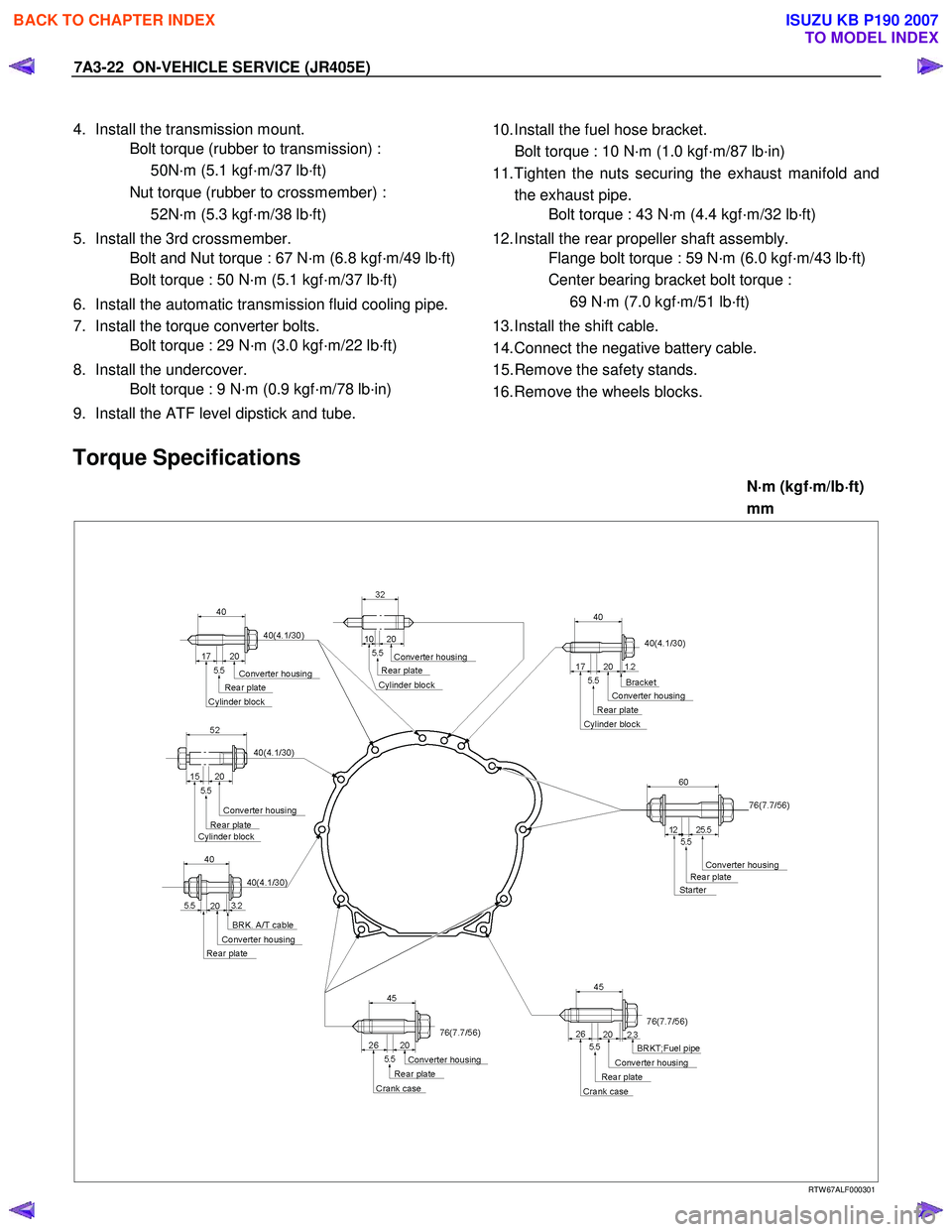
Torque Specifications
N ⋅
⋅⋅
⋅
m (kgf ⋅
⋅⋅
⋅
m/lb ⋅
⋅⋅
⋅
ft)
mm
RTW 67ALF000301
BACK TO CHAPTER INDEX
TO MODEL INDEX
ISUZU KB P190 2007
Page 4802 of 6020
7C-24 CLUTCH
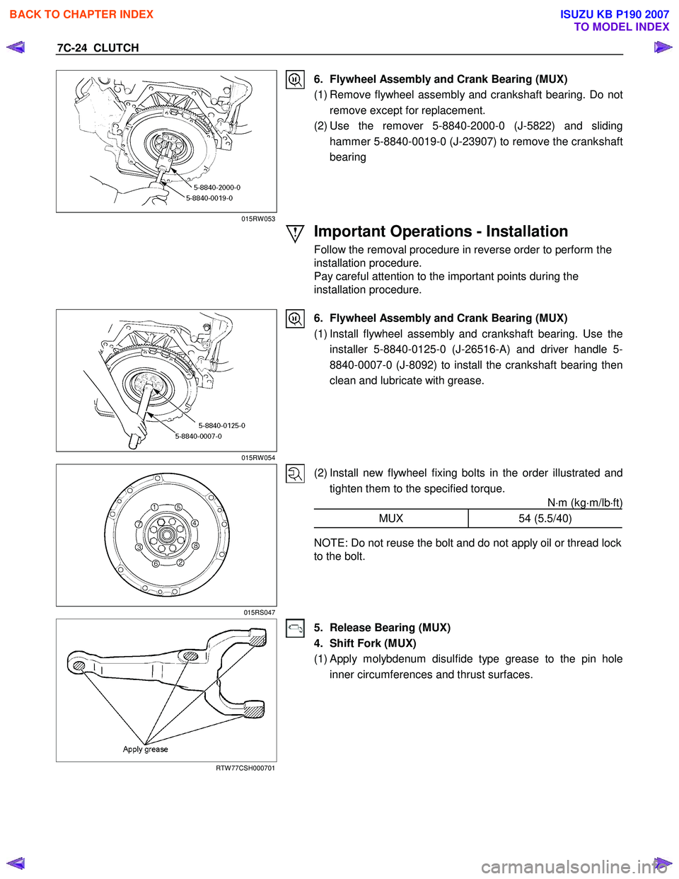
015RW 053
6. Flywheel Assembly and Crank Bearing (MUX)
(1) Remove flywheel assembly and crankshaft bearing. Do not remove except for replacement.
(2) Use the remover 5-8840-2000-0 (J-5822) and sliding hammer 5-8840-0019-0 (J-23907) to remove the crankshaft
bearing
Important Operations - Installation
Follow the removal procedure in reverse order to perform the
installation procedure.
Pay careful attention to the important points during the
installation procedure.
015RW 054
6. Flywheel Assembly and Crank Bearing (MUX)
(1) Install flywheel assembly and crankshaft bearing. Use the installer 5-8840-0125-0 (J-26516-A) and driver handle 5-
8840-0007-0 (J-8092) to install the crankshaft bearing then
clean and lubricate with grease.
015RS047
(2) Install new flywheel fixing bolts in the order illustrated and tighten them to the specified torque. N⋅m (kg ⋅m/lb ⋅ft)
MUX 54 (5.5/40)
NOTE: Do not reuse the bolt and do not apply oil or thread lock
to the bolt.
RTW 77CSH000701
5. Release Bearing (MUX)
4. Shift Fork (MUX)
(1)
Apply molybdenum disulfide type grease to the pin hole
inner circumferences and thrust surfaces.
BACK TO CHAPTER INDEX
TO MODEL INDEX
ISUZU KB P190 2007
Page 4803 of 6020
CLUTCH 7C-25
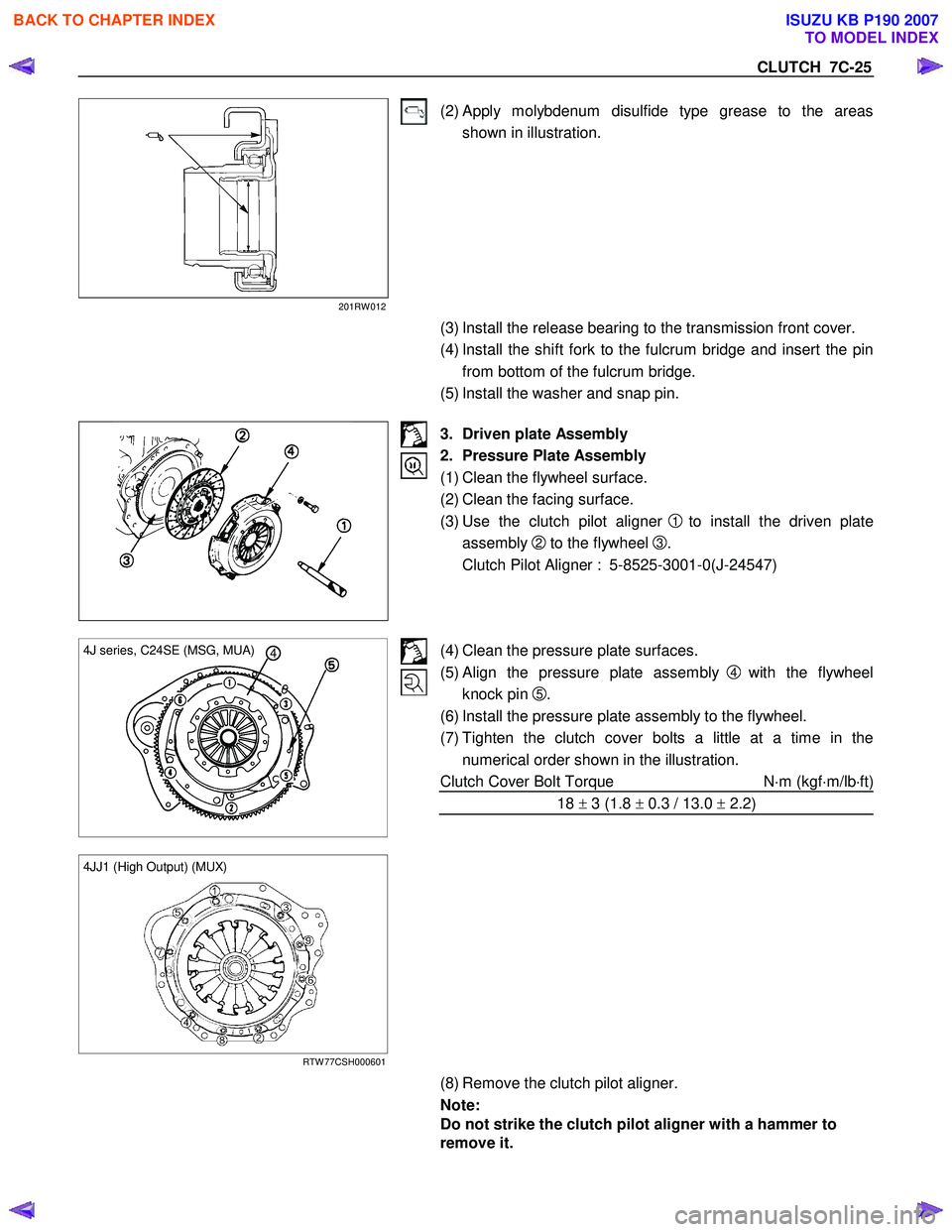
201RW 012
(2) Apply molybdenum disulfide type grease to the areas shown in illustration.
(3) Install the release bearing to the transmission front cover.
(4) Install the shift fork to the fulcrum bridge and insert the pin from bottom of the fulcrum bridge.
(5) Install the washer and snap pin.
3. Driven plate Assembly
2. Pressure Plate Assembly
(1) Clean the flywheel surface.
(2) Clean the facing surface.
(3) Use the clutch pilot aligner
1 to install the driven plate
assembly
2 to the flywheel 3.
Clutch Pilot Aligner : 5-8525-3001-0(J-24547)
4 4J series, C24SE (MSG, MUA)
(4) Clean the pressure plate surfaces.
(5) Align the pressure plate assembly
4 with the flywheel
knock pin
5.
(6) Install the pressure plate assembly to the flywheel.
(7) Tighten the clutch cover bolts a little at a time in the numerical order shown in the illustration.
Clutch Cover Bolt Torque N⋅m (kgf ⋅m/lb ⋅ft)
18 ± 3 (1.8 ± 0.3 / 13.0 ± 2.2)
4JJ1 (High Output) (MUX)
RTW 77CSH000601
(8) Remove the clutch pilot aligner.
Note:
Do not strike the clutch pilot aligner with a hammer to
remove it.
BACK TO CHAPTER INDEX
TO MODEL INDEX
ISUZU KB P190 2007