2007 ISUZU KB P190 wheel bolt torque
[x] Cancel search: wheel bolt torquePage 843 of 6020

6A – 38 ENGINE MECHANICAL
6. Front propeller shaft (for 4x4 model)
Remove the spline yoke flange bolt at the transfer output
shaft.
Do not allow the spline yoke to fall away from the front
propeller shaft.
If the spline yoke should fall away from the front propeller
shaft, align the setting marks on the spline yoke and the
propeller shaft to reassemble the two marks. The setting
marks are punched circles approx. 3mm (0.12 in) in
diameter.
7. Clutch slave cylinder (for M/T model)
8. ATF pipe (for A/T model)
9 Shift control cable (for A/T model)
10. Transmission sensor harness Remove the vehicle speed sensor connector, inhibitor
switch connector (A/T), ATF temperature sensor
connector, back up light switch connector (M/T) from
transmission.
11. Breather hose (for A/T model)
12. Transmission shift lever (for M/T model) Remove the shift lever from the floor.
13. Transfer shift lever (for 4x4 model) Remove the shift lever from the floor.
14. Transmission member 1) Support the transmission with the transmission jack.
2) Remove the transmission member mounting bolts fixing the transmission member to the chassis frame.
15. Torque converter bolt (for A/T model) 1) Remove the under cover under the torque converter housing.
2) Rotate the flywheel by using tire lever or some other tool, and then remove the torque converter bolts.
16. Transmission coupling bolt 1) Support the engine with the garage jack.
2) Use the jack to slightly lower the transmission.
3) Remove the transmission coupling bolts.
17. Transmission (and transfer) Separate the transmission (and transfer) from the
engine.Take care not to damage the transmission, the
engine, and their related parts..
F06R300007
P1010025
BACK TO CHAPTER INDEX
TO MODEL INDEX
ISUZU KB P190 2007
Page 915 of 6020

6A – 110 ENGINE MECHANICAL
17. Cylinder Body Rear Plate
1. Align the rear plate with the cylinder body knock pins.
2. Tighten the rear plate to the specified torque.
Rear Plate Torque N·m(kg·m/lbft)
82 (8.4/61)
18. Flywheel
1. Apply a coat of engine oil to the threads of the flywheel bolts.
2. Align the flywheel with the crankshaft dowel pin.
3. Tighten the flywheel bolts in the numerical order shown in the illustration.
Gear stoper: 5-8840-0214-0
Flywheel Bolt Torque N·m(kg·m/lbft)
118 (12/87)
19. Crankshaft Timing Gear
Use the crankshaft timing gear installer (1) to install the
crankshaft timing gear (2).
The crankshaft timing gear setting mark must be facing
outward.
Crankshaft Timing Gear Installer: 9-8522-0020-0
20. Idler Gear Shaft
21. Idler Gear "A"
1. Turn the crankshaft clockwise to set the DTC of the No.1 piston.
2. Apply engine oil to the idler gear and the idler gear shaft.
The idler gear shaft oil hole (A) must be facing up.
3. Position the idler gear setting marks so that they are facing the front of the engine.
015LX113
020R100001
020RY00034
020RY00035
BACK TO CHAPTER INDEX
TO MODEL INDEX
ISUZU KB P190 2007
Page 920 of 6020

ENGINE MECHANICAL 6A – 115
RTW 46ASH002201
4JA1T(L):
4. Tighten the injection pump bolts to the specified torque.
5. Install the injection pump bracket (4) and the bracket bolts (5) and (6) to the cylinder body. Temporarily tighten
the bracket bolts.
6. Tighten the bracket bolts (5) to the specified torque.
7. Tighten the bracket bolts (6) to the specified torque.
Injection pump Bracket Bolt Torque (6) N·m(kg·m/lbft)
19 (1.9/14)
Injection pump Bracket Bolt Torque (5) N·m(kg·m/lbft)
40 (4.1/30)
030RY00007
24. Water Pump
1. Apply the recommended liquid gasket or its equivalent to the water pump at the position shown in the
illustration.
Do not apply an excessive amount of liquid gasket.
2. Tighten the water pump bolts to the specified torque.
W ater Pump Bolt Torque N·m(kg·m/lbft)
20 (2.0/14)
25.Timing Gear Case Cover
1.
Align the gear case with the timing gear case knock pin
and then install the timing gear case cover.
2. Tighten the gear case cover bolts to the specified torque.
Gear Case Cover Bolt Torque N·m(kg·m/lbft)
M8 19 (1.9/14)
M12 76 (7.7/56)
26. Crankshaft Damper Pulley
Tighten the crankshaft damper pulley bolt to the specified
torque.
Note:
Hold the flywheel ring gear stationary to prevent the
crankshaft from turning when tightening the damper
pulley bolt.
Crankshaft Damper Pulley Bolt Torque N·m(kg·m/lbft)
206 (21/152)
Take care not to damage the crankshaft damper pulley
boss.
014R100014
020R300004
BACK TO CHAPTER INDEX
TO MODEL INDEX
ISUZU KB P190 2007
Page 973 of 6020

FUEL SYSTEM 6C – 9
Removal
CAUTION: When repair to the fuel system has been
completed, start engine and check the fuel system for
loose connection or leakage. For the fuel system
diagnosis, see Section “Driveability and Emission".
1. Disconnect battery ground cable.
2. Loosen slowly the fuel filler cap.
NOTE: Be careful not to spouting out fuel because of change
the pressure in the fuel tank.
NOTE: Cover opening of the filler neck to prevent any dust
entering.
3. Jack up the vehicle.
4. Support underneath of the fuel tank with a lifter.
5. Remove the inner liner of the wheel house at rear left side.
6. Remove fixing bolt of the filler neck from the body.
7. Disconnect the quick connector (3) of the fuel tube from the
fuel pipe.
NOTE: Cover the quick connector to prevent any dust entering
and fuel leakage.
NOTE: Refer to “Fuel Tube/Quick Connector Fittings” in this
section when performing any repairs.
8. Remove fixing bolt (1) of the tank band and remove the tank band (2).
9. Disconnect the pump and sender connector on the fuel
pump and remove the harness from weld clip on the fuel
tank.
10. Lower the fuel tank (5).
NOTE: W hen lower the fuel tank from the vehicle, don’t scratch
each hose and tube by around other parts.
Installation
1. Raise the fuel tank.
NOTE: W hen raise the fuel tank to the vehicle, don’t scratch
each hose and tube by around other parts.
2. Connect the pump and sender connector to the fuel pump and install the harness to weld clip on the tank.
NOTE: The connector must be certainly connected against
stopper.
3. Install the tank band and fasten bolt.
Torque N·m (kg·m / lb ft)
68 (6.9 / 50)
NOTE: The anchor of the tank band must be certainly installed
to guide hole on frame.
4. Connect the quick connector of the fuel tube to the fuel pipe and the evapo tube from evapo joint connector.
NOTE: Pull off the left checker on the fuel pipe.
NOTE: Refer to “Fuel Tube/Quick Connector Fittings” in this
section when performing any repairs.
BACK TO CHAPTER INDEX
TO MODEL INDEX
ISUZU KB P190 2007
Page 1363 of 6020

ENGINE MECHANICAL (4JK1/4JJ1) 6A-3
ISUZU DIESEL ENGINE (4JK1/4JJ1)
Service Precautions
Matters that require attention in terms of
maintenance
To prevent damage to the engine and ensure reliabilit
y
of its performance, pay attention to the following in
maintaining the engine:
• W hen lifting up or supporting the engine, do not
apply a jack on the oil pan.
W hen taking down the engine on the ground, do not make the bearing surface of the oil pan touch
the ground directly. Use a wooden frame, fo
r
example, to support the engine with the engine
foot and the flywheel housing.
Because there is only a small clearance between the oil pan and the oil pump strainer, it can
damage the oil pan and the oil strainer.
• W hen the air duct or air cleaner is removed, cove
r
the air intake opening to prevent foreign matter
from getting into the cylinder. If it gets
contaminated, it can considerably damage the
cylinder and others while the engine is operating.
• W hen maintaining the engine, never fail to remove
the battery earth cable. If not, it may damage the
wire harness or electrical parts. If you need
electricity on for the purpose of inspection, fo
r
instance, watch out for short circuits and others.
•
Apply engine oil to the sliding contact surfaces of
the engine before reassembling it. This ensures
adequate lubrication when the engine is first
started.
• W hen valve train parts, pistons, piston rings,
connecting rods, connecting rod bearings o
r
crankshaft journal bearings are removed, put them
in order and keep them.
• W hen installing them, put them back in the same
location they were removed from.
• Gaskets, oil seals, O-rings, etc. must be replaced
with new ones when the engine is reassembled.
•
As for parts where a liquid gasket is used, remove
an old liquid gasket completely and clean it up
thoroughly so that no oil, water or dust is clinging
to them. Then, apply the designated liquid gasket
to each place anew before assembly.
• Surfaces covered with liquid gasket must be
assembled within 5 minutes of gasket application.
If more than 5 minutes has elapsed, remove the
existing liquid gasket and apply a new liquid
gasket.
• W hen assembling or installing parts, fasten them
with the prescribed tightening torque so that the
y
are installed properly.
Matters that require attention in specifically dealing
with this engine.
Holes or clearances in the fuel system, which serve as
a passage of fuel, including the inside of the injector,
are made with extreme precision. For this reason, the
y
are highly sensitive to foreign matter and, if it gets in, it
can lead to an accident on the road, for instance; thus,
make sure that foreign matter is prevented from getting
in.
W hen servicing the fuel system, every precaution must
be taken to prevent the entry of foreign material into the
system.
• Before beginning the service procedure, wash the
fuel line and the surrounding area.
• Perform the service procedures with clean hands.
Do not wear work gloves.
• Immediately after removing the fuel hose and/o
r
fuel pipe, carefully tape vinyl bags over the
exposed ends of the hose or pipe.
• If parts are to be replaced (fuel hose, fuel pipe,
etc.) do not open the new part packaging until
installation.
Work procedure
• The fuel opening must be quickly sealed when
removing the fuel pipe, injection pipe, fuel injector,
fuel supply pump, and fuel rail.
• The eyebolts and gasket must be stored in a clean
parts box with a lid to prevent adhesion of foreign
matter.
• Fuel leakage could cause fires. Therefore, afte
r
finishing the work, wipe off the fuel that has leaked
out and make sure there is no fuel leakage afte
r
starting the engine.
BACK TO CHAPTER INDEX
TO MODEL INDEX
ISUZU KB P190 2007
Page 1474 of 6020

6A-114 ENGINE MECHANICAL (4JK1/4JJ1)
015RY00010
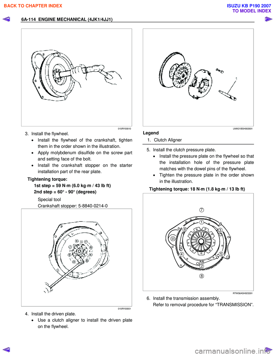
3. Install the flywheel.
• Install the flywheel of the crankshaft, tighten
them in the order shown in the illustration.
•
Apply molybdenum disulfide on the screw part
and setting face of the bolt.
• Install the crankshaft stopper on the starte
r
installation part of the rear plate.
Tightening torque: 1st step = 59 N ⋅
⋅⋅
⋅
m (6.0 kg ⋅
⋅⋅
⋅
m / 43 lb ft)
2nd step = 60° - 90° (degrees)
Special tool
Crankshaft stopper: 5-8840-0214-0
015RY00001
4. Install the driven plate.
• Use a clutch aligner to install the driven plate
on the flywheel.
LNW 21BSH002601
Legend
1. Clutch Aligner
5. Install the clutch pressure plate.
• Install the pressure plate on the flywheel so that
the installation hole of the pressure plate
matches with the dowel pins of the flywheel.
• Tighten the pressure plate in the order shown
in the illustration.
Tightening torque: 18 N ⋅
⋅⋅
⋅
m (1.8 kg ⋅
⋅⋅
⋅
m / 13 lb ft)
RTW 56ASH023301
6. Install the transmission assembly.
Refer to removal procedure for “TRANSMISSION”.
BACK TO CHAPTER INDEX
TO MODEL INDEX
ISUZU KB P190 2007
Page 1481 of 6020

ENGINE MECHANICAL (4JK1/4JJ1) 6A-121
3. Remove the crankshaft pulley.
Note:
Do not reuse the bolt and the washer.
LNW 61ASH005301
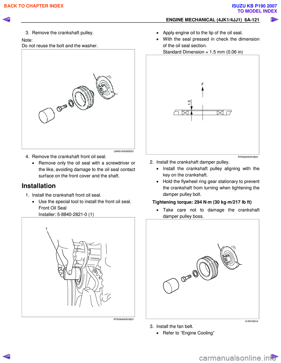
4. Remove the crankshaft front oil seal.
• Remove only the oil seal with a screwdriver o
r
the like, avoiding damage to the oil seal contact
surface on the front cover and the shaft.
Installation
1. Install the crankshaft front oil seal. • Use the special tool to install the front oil seal.
Front Oil Seal
Installer: 5-8840-2821-0 (1)
RTW 56ASH016501
• Apply engine oil to the lip of the oil seal.
• W ith the seal pressed in check the dimension
of the oil seal section.
Standard Dimension = 1.5 mm (0.06 in)
RTW 56ASH016601
2. Install the crankshaft damper pulley.
• Install the crankshaft pulley aligning with the
key on the crankshaft.
• Hold the flywheel ring gear stationary to prevent
the crankshaft from turning when tightening the
damper pulley bolt.
Tightening torque: 294 N ⋅
⋅⋅
⋅
m (30 kg ⋅
⋅⋅
⋅
m/217 lb ft)
• Take care not to damage the crankshaft
damper pulley boss.
014R100014
3. Install the fan belt.
• Refer to “Engine Cooling”
BACK TO CHAPTER INDEX
TO MODEL INDEX
ISUZU KB P190 2007
Page 1514 of 6020

6A-154 ENGINE MECHANICAL (4JK1/4JJ1)
6. Install the rear plate.
• Tighten the bolts to the specified torque.
Tightening torque: 82 N ⋅
⋅⋅
⋅
m (8.4 kg ⋅
⋅⋅
⋅
m / 61 lb ft)
7. Install the flywheel.
Refer to “Flywheel”.
8. Connect the earth terminal of crank case side.
Note:
Do not allow the caulked portion of the terminal to
interfere with nearby parts.
9. Install the oil level gage guide tube. • Apply the engine oil to the O-ring.
• Tighten the bolts to the specified torque.
Tightening torque: 25 N ⋅
⋅⋅
⋅
m (2.5 kg ⋅
⋅⋅
⋅
m / 18 lb ft)
10. Install the engine assembly.
Refer to “Engine Assembly”.
BACK TO CHAPTER INDEX
TO MODEL INDEX
ISUZU KB P190 2007