2007 ISUZU KB P190 oil change
[x] Cancel search: oil changePage 2324 of 6020
6E–154 ENGINE DRIVEABILITY AND EMISSIONS
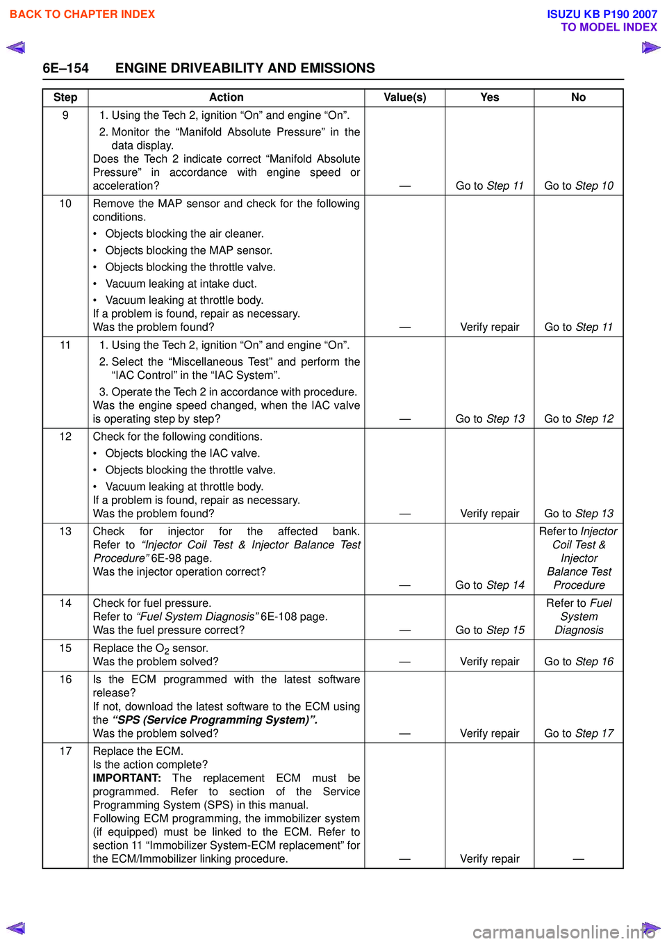
9 1. Using the Tech 2, ignition “On” and engine “On”. 2. Monitor the “Manifold Absolute Pressure” in thedata display.
Does the Tech 2 indicate correct “Manifold Absolute
Pressure” in accordance with engine speed or
acceleration? — Go to Step 11Go to Step 10
10 Remove the MAP sensor and check for the following conditions.
• Objects blocking the air cleaner.
• Objects blocking the MAP sensor.
• Objects blocking the throttle valve.
• Vacuum leaking at intake duct.
• Vacuum leaking at throttle body.
If a problem is found, repair as necessary.
Was the problem found? — Verify repair Go to Step 11
11 1. Using the Tech 2, ignition “On” and engine “On”. 2. Select the “Miscellaneous Test” and perform the“IAC Control” in the “IAC System”.
3. Operate the Tech 2 in accordance with procedure.
Was the engine speed changed, when the IAC valve
is operating step by step? — Go to Step 13Go to Step 12
12 Check for the following conditions. • Objects blocking the IAC valve.
• Objects blocking the throttle valve.
• Vacuum leaking at throttle body.
If a problem is found, repair as necessary.
Was the problem found? — Verify repair Go to Step 13
13 Check for injector for the affected bank. Refer to “Injector Coil Test & Injector Balance Test
Procedure” 6E-98 page .
Was the injector operation correct? —Go to Step 14Refer to
Injector
Coil Test & Injector
Balance Test Procedure
14 Check for fuel pressure. Refer to “Fuel System Diagnosis” 6E-108 page.
Was the fuel pressure correct? — Go to Step 15Refer to
Fuel
System
Diagnosis
15 Replace the O
2 sensor.
Was the problem solved? — Verify repair Go to Step 16
16 Is the ECM programmed with the latest software release?
If not, download the latest software to the ECM using
the “SPS (Service Programming System)”.
Was the problem solved? — Verify repair Go to Step 17
17 Replace the ECM. Is the action complete?
IMPORTANT: The replacement ECM must be
programmed. Refer to section of the Service
Programming System (SPS) in this manual.
Following ECM programming, the immobilizer system
(if equipped) must be linked to the ECM. Refer to
section 11 “Immobilizer System-ECM replacement” for
the ECM/Immobilizer linking procedure. — Verify repair —
Step
Action Value(s) Yes No
BACK TO CHAPTER INDEX
TO MODEL INDEX
ISUZU KB P190 2007
Page 2357 of 6020
ENGINE DRIVEABILITY AND EMISSIONS 6E–187
mating, broken locks, improperly formed or damaged
terminals, and poor terminal-to-wire connections.
• Damaged harness - Inspect the wiring harness for damage; Open circuits, shorts to ground, or shorts to
Voltage. If the harness appears to be OK, observe the Tech 2 display related to DTC P0351 or P0352
while moving the connector and wiring related to the
ignition system. A change in the display will indicate
the location of the fault.
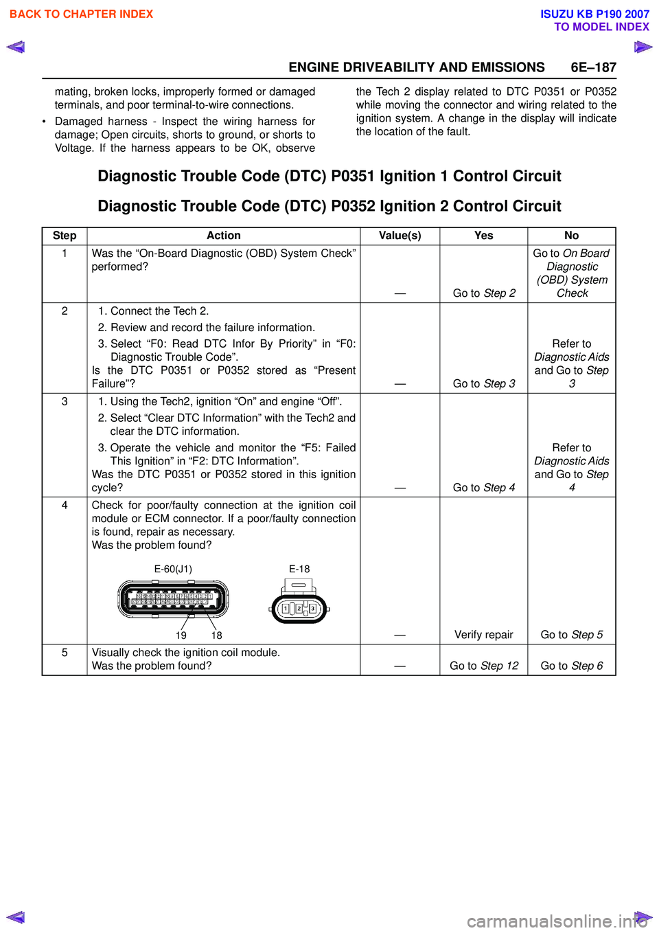
Diagnostic Trouble Code (DTC) P0351 Ignition 1 Control Circuit
Diagnostic Trouble Code (DTC) P0352 Ignition 2 Control Circuit
Step Action Value(s) Yes No
1 Was the “On-Board Diagnostic (OBD) System Check” performed?
—Go to Step 2Go to
On Board
Diagnostic
(OBD) System Check
2 1. Connect the Tech 2. 2. Review and record the failure information.
3. Select “F0: Read DTC Infor By Priority” in “F0: Diagnostic Trouble Code”.
Is the DTC P0351 or P0352 stored as “Present
Failure”? — Go to Step 3Refer to
Diagnostic Aids and Go to Step
3
3 1. Using the Tech2, ignition “On” and engine “Off”. 2. Select “Clear DTC Information” with the Tech2 andclear the DTC information.
3. Operate the vehicle and monitor the “F5: Failed This Ignition” in “F2: DTC Information”.
Was the DTC P0351 or P0352 stored in this ignition
cycle? — Go to Step 4Refer to
Diagnostic Aids and Go to Step
4
4 Check for poor/faulty connection at the ignition coil module or ECM connector. If a poor/faulty connection
is found, repair as necessary.
Was the problem found?
— Verify repair Go to Step 5
5 Visually check the ignition coil module. Was the problem found? — Go to Step 12Go to Step 6
19 18
E-60(J1) E-18
BACK TO CHAPTER INDEX
TO MODEL INDEX
ISUZU KB P190 2007
Page 2383 of 6020
ENGINE DRIVEABILITY AND EMISSIONS 6E–213
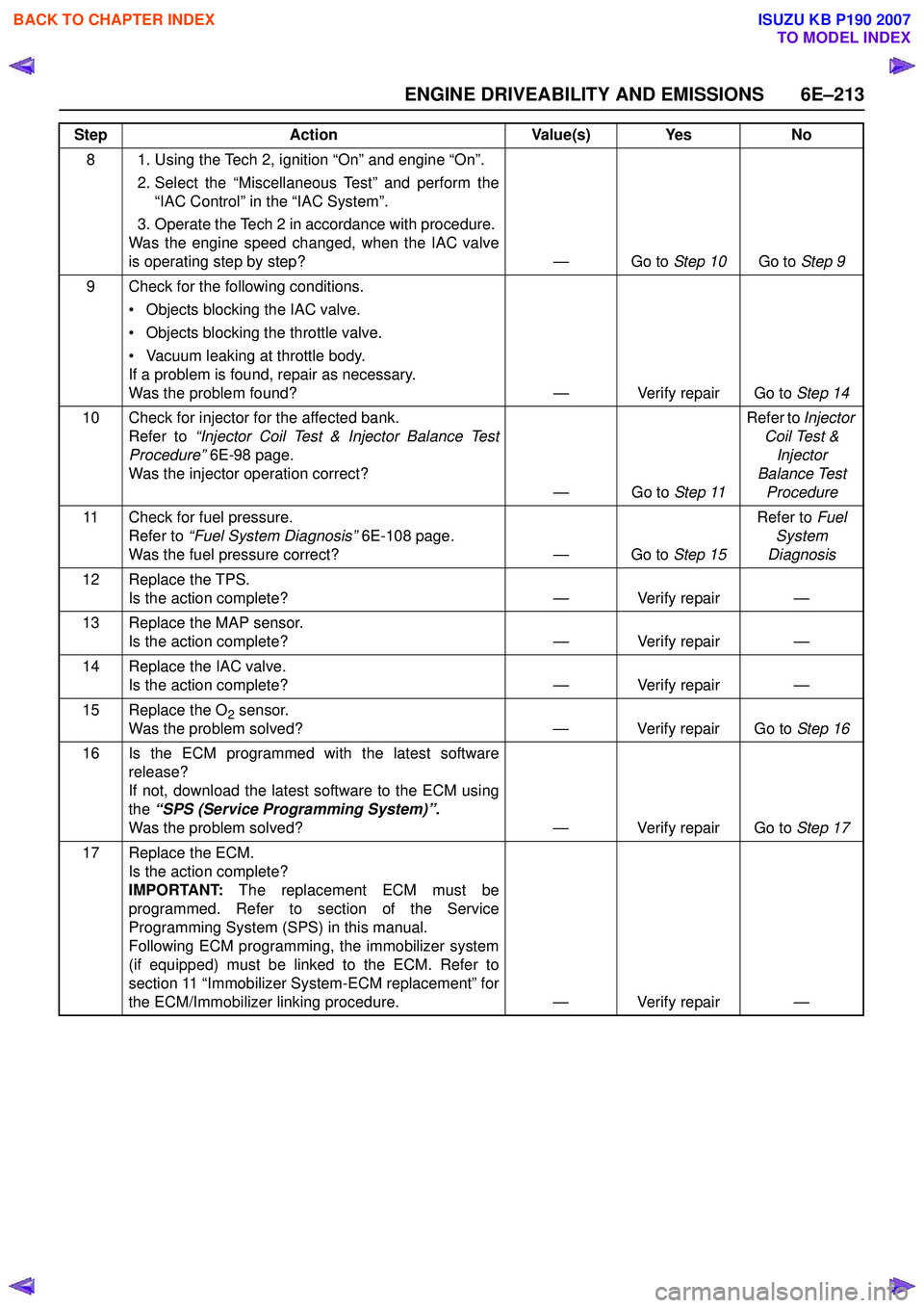
8 1. Using the Tech 2, ignition “On” and engine “On”. 2. Select the “Miscellaneous Test” and perform the“IAC Control” in the “IAC System”.
3. Operate the Tech 2 in accordance with procedure.
Was the engine speed changed, when the IAC valve
is operating step by step? — Go to Step 10Go to Step 9
9 Check for the following conditions. • Objects blocking the IAC valve.
• Objects blocking the throttle valve.
• Vacuum leaking at throttle body.
If a problem is found, repair as necessary.
Was the problem found? — Verify repair Go to Step 14
10 Check for injector for the affected bank. Refer to “Injector Coil Test & Injector Balance Test
Procedure” 6E-98 page .
Was the injector operation correct? —Go to Step 11Refer to
Injector
Coil Test & Injector
Balance Test Procedure
11 Check for fuel pressure. Refer to “Fuel System Diagnosis” 6E-108 page.
Was the fuel pressure correct? — Go to Step 15Refer to
Fuel
System
Diagnosis
12 Replace the TPS. Is the action complete? — Verify repair —
13 Replace the MAP sensor. Is the action complete? — Verify repair —
14 Replace the IAC valve. Is the action complete? — Verify repair —
15 Replace the O
2 sensor.
Was the problem solved? — Verify repair Go to Step 16
16 Is the ECM programmed with the latest software release?
If not, download the latest software to the ECM using
the “SPS (Service Programming System)”.
Was the problem solved? — Verify repair Go to Step 17
17 Replace the ECM. Is the action complete?
IMPORTANT: The replacement ECM must be
programmed. Refer to section of the Service
Programming System (SPS) in this manual.
Following ECM programming, the immobilizer system
(if equipped) must be linked to the ECM. Refer to
section 11 “Immobilizer System-ECM replacement” for
the ECM/Immobilizer linking procedure. — Verify repair —
Step
Action Value(s) Yes No
BACK TO CHAPTER INDEX
TO MODEL INDEX
ISUZU KB P190 2007
Page 2386 of 6020
6E–216 ENGINE DRIVEABILITY AND EMISSIONS
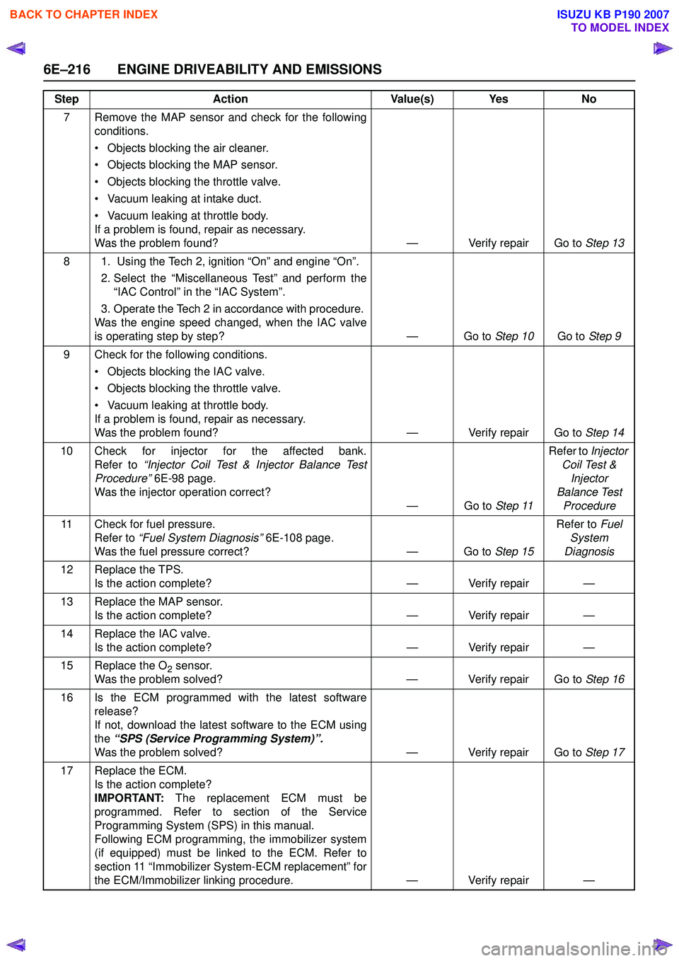
7 Remove the MAP sensor and check for the followingconditions.
• Objects blocking the air cleaner.
• Objects blocking the MAP sensor.
• Objects blocking the throttle valve.
• Vacuum leaking at intake duct.
• Vacuum leaking at throttle body.
If a problem is found, repair as necessary.
Was the problem found? — Verify repair Go to Step 13
8 1. Using the Tech 2, ignition “On” and engine “On”. 2. Select the “Miscellaneous Test” and perform the“IAC Control” in the “IAC System”.
3. Operate the Tech 2 in accordance with procedure.
Was the engine speed changed, when the IAC valve
is operating step by step? — Go to Step 10Go to Step 9
9 Check for the following conditions. • Objects blocking the IAC valve.
• Objects blocking the throttle valve.
• Vacuum leaking at throttle body.
If a problem is found, repair as necessary.
Was the problem found? — Verify repair Go to Step 14
10 Check for injector for the affected bank. Refer to “Injector Coil Test & Injector Balance Test
Procedure” 6E-98 page .
Was the injector operation correct? —Go to Step 11Refer to
Injector
Coil Test & Injector
Balance Test Procedure
11 Check for fuel pressure. Refer to “Fuel System Diagnosis” 6E-108 page.
Was the fuel pressure correct? — Go to Step 15Refer to
Fuel
System
Diagnosis
12 Replace the TPS. Is the action complete? — Verify repair —
13 Replace the MAP sensor. Is the action complete? — Verify repair —
14 Replace the IAC valve. Is the action complete? — Verify repair —
15 Replace the O
2 sensor.
Was the problem solved? — Verify repair Go to Step 16
16 Is the ECM programmed with the latest software release?
If not, download the latest software to the ECM using
the “SPS (Service Programming System)”.
Was the problem solved? — Verify repair Go to Step 17
17 Replace the ECM. Is the action complete?
IMPORTANT: The replacement ECM must be
programmed. Refer to section of the Service
Programming System (SPS) in this manual.
Following ECM programming, the immobilizer system
(if equipped) must be linked to the ECM. Refer to
section 11 “Immobilizer System-ECM replacement” for
the ECM/Immobilizer linking procedure. — Verify repair —
Step
Action Value(s) Yes No
BACK TO CHAPTER INDEX
TO MODEL INDEX
ISUZU KB P190 2007
Page 2402 of 6020
6E–232 ENGINE DRIVEABILITY AND EMISSIONS
SYMPTOM DIAGNOSIS
PRELIMINARY CHECKS
Before using this section, perform the “On-Board
Diagnostic (OBD) System Check” and verify all of the
following items:
• The engine control module (ECM) and malfunction indicator lamp (MIL = Check Engine Lamp) are
operating correctly.
• There are no Diagnostic Trouble Code(s) stored.
• Tech 2 data is within normal operating range. Refer to Typical Scan Data Values.
• Verify the customer complaint and locate the correct symptom in the table of contents. Perform the
procedure included in the symptom chart.
VISUAL/PHYSICAL CHECK
Several of the symptom procedures call for a careful
visual/physical check. This can lead to correcting a
problem without further checks and can save valuable
time. This check should include the following items:
• ECM grounds for cleanliness, tightness and proper location.
• Vacuum hoses for splits, kinks, and proper connection, shown on the “Emission Control System
Schematics”. Check thoroughly for any type of leak or
restriction.
• Air intake ducts for collapsed or damaged areas.
• Air leaks at throttle body mounting area, manifold absolute pressure (MAP) sensor and intake manifold
sealing surfaces.
• Ignition wires for cracking, harness, and carbon tracking.
• Wiring for proper connections, pinches and cuts.
INTERMITTENT
Important: An intermittent problem may or may not turn
on the malfunction indicator lamp (MIL) or store a
Diagnostic Trouble Code. Do NOT use the Diagnostic
Trouble Code (DTC) charts for intermittent problems.
The fault must be present to locate the problem.
Most intermittent problems are cased by faulty electrical
connections or wiring. Perform a careful visual/physical
check for the following conditions.
• Poor mating of the connector halves or a terminal not fully seated in the connector (backed out).
• Improperly formed or damaged terminal.
• All connector terminals in the problem circuit should be carefully checked for proper contact tension.
• Poor terminal-to-wire connection. This requires removing the terminal form the connector body to
check.
• Ignition coils shorted to ground and arcing at ignition wires or plugs. • MIL (Check Engine Lamp) wire to ECM shorted to
ground.
• Poor ECM grounds. Refer to the ECM wiring diagrams.
Road test the vehicle with a Digital Multimeter
connected to a suspected circuit. An abnormal voltage
when the malfunction occurs is a good indication that
there is a fault in the circuit being monitored.
Using Tech 2 to help detect intermittent conditions. The
Tech 2 has several features that can be used to located
an intermittent condition.
An intermittent MIL (Check Engine Lamp) with no stored
Diagnostic Trouble Code may be caused by the
following:
• Ignition coil shorted to ground and arcing at ignition wires or plugs.
• MIL (Check Engine Lamp) wire to ECM short to ground.
• Poor ECM grounds. Refer to the ECM wiring diagrams.
Check for improper installation of electrical options such
as light, cellular phones, etc. Check all wires from ECM
to the ignition control module for poor connections.
Check for an open diode across the A/C compressor
clutch and check for other open diodes (refer to wiring
diagrams in Electrical Diagnosis).
If problem has not been found, refer to ECM connector
symptom tables.
• Check the “Broadcast Code” of the ECM, and compare it with the latest Isuzu service bulletins and/
or Isuzu EEPROM reprogramming equipment to
determine if an update to the ECM’s reprogrammable
memory has been released.
To check the “Broadcast Code”, connect the Tech 2,
then look for “ID info.” then select “Broadcast Code”.
This should display a 4 character code, such as “XBYA”
(example only).
This identifies the contents of the reprogrammable
software and calibration contained in the ECM.
If the “Broadcast Code” is not the most current
available, it is advisable to reprogram the ECM’s
EEPROM memory, which may either help identify a
hard-to find problem or may fix the problem.
The Service Programming System (SPS) will not allow
incorrect software programming or incorrect calibration
changes.
BACK TO CHAPTER INDEX
TO MODEL INDEX
ISUZU KB P190 2007
Page 2442 of 6020
6E–272 ENGINE DRIVEABILITY AND EMISSIONS
FUEL INJECTOR
Removal Procedure
NOTE: If the fuel injectors are leaking, the engine oil
may be contaminated with fuel. Check the oil for signs
of contamination and change the oil and filter if
necessary.
NOTE: Use care in removing the fuel injector in order to
prevent damage to the fuel injector al connector pins or
fuel injector nozzles. The fuel injector is an al
component and should not be immersed in any type of
cleaner as this may damage the fuel injector.
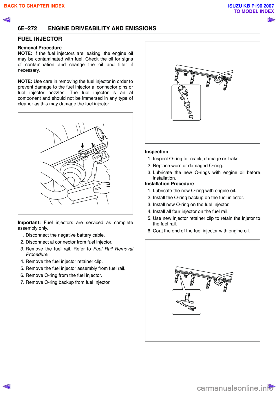
Important: Fuel injectors are serviced as complete
assembly only.
1. Disconnect the negative battery cable.
2. Disconnect al connector from fuel injector.
3. Remove the fuel rail. Refer to Fuel Rail Removal
Procedure .
4. Remove the fuel injector retainer clip.
5. Remove the fuel injector assembly from fuel rail.
6. Remove O-ring from the fuel injector.
7. Remove O-ring backup from fuel injector. Inspection
1. Inspect O-ring for crack, damage or leaks.
2. Replace worn or damaged O-ring.
3. Lubricate the new O-rings with engine oil before installation.
Installation Procedure
1. Lubricate the new O-ring with engine oil.
2. Install the O-ring backup on the fuel injector.
3. Install new O-ring on the fuel injector.
4. Install all four injector on the fuel rail.
5. Use new injector retainer clip to retain the injetor to the fuel rail.
6. Coat the end of the fuel injector with engine oil.
BACK TO CHAPTER INDEX
TO MODEL INDEX
ISUZU KB P190 2007
Page 2471 of 6020
ENGINE LUBRICATION 6G-7
Inspection and Repair
CAUTION: Make necessary correction or parts replacement if wear, damage or any other
abnormal conditions are found through
inspection.
Reassembly
To install, follows the disassembly steps in the reverse order.
Important
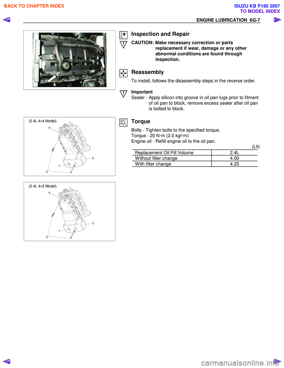
Sealer - Apply silicon into groove in oil pan lugs prior to fitment of oil pan to block, remove excess sealer after oil pan
is bolted to block.
(2.4L 4 ×4 Model)
4
3
1
2
(2.4L 4 ×2 Model)
4
3
1
2
Torque
Bolts - Tighten bolts to the specified torque.
Torque : 20 N xm (2.0 kgf xm)
Engine oil - Refill engine oil to the oil pan. (Lit)
Replacement Oil Fill Volume 2.4L
W ithout filter change 4.00
W ith filter change 4.25
BACK TO CHAPTER INDEX
TO MODEL INDEX
ISUZU KB P190 2007
Page 2504 of 6020
Engine Mechanical – V6 Page 6A1–25
• Do not use any other method or technique to remove sealant or gasket material from a part.
• Do not use abrasive pads, sand paper, or power tools to clean the gasket surfaces as these methods of cleaning
can cause damage to the component sealing surfaces. Abrasive pads also produce fine grit that the oil filter cannot
remove from the oil. This grit is abrasive and has been known to cause internal engine damage.
Assembling Components
• W hen assembling components, use only the sealant specified or equivalent in the service procedure.
• Sealing surfaces should be clean and free of debris or oil.
• Specific components such as crankshaft oil seals or valve stem oil seals may require lubrication during assembly.
• Components requiring lubrication will be identified in the service procedure.
• W hen applying sealant to a component, apply the amount specified in the service procedure.
• Do not allow the sealant to enter into any blind threaded holes as it may prevent the bolt from clamping correctly or
cause component damage when tightened.
• Only ever tighten bolts to the correct torque specification. Do not over-tighten.
Use of Room Temperature Vulcanising and Anaerobic Sealer
CAUTION
A number of sealant types are commonly
used in engines. Examples are; room
temperature vulcanising (RTV) sealer,
anaerobic gasket eliminator sealer, and
anaerobic thread sealant and pipe joint
compound. The correct type of sealant and
amount must be used in the specified location
to prevent oil leaks. Do not interchange the
different types of sealers.
Room Temperature Vulcanising Sealer
• Room temperature vulcanising (RTV) sealant hardens when exposed to air. This type of sealer is used where two
non-rigid parts (such as the intake manifold and the engine block) are assembled together.
• Do not use RTV sealant in areas where extreme temperatures are experienced. These areas include the exhaust
manifold, head gasket, or other surfaces where a gasket eliminator is specified.
• Follow all safety recommendations and directions that are on the container.
• To remove the sealant or the gasket material, refer to Replacing Engine Gaskets.
• Apply RTV to a clean surface. Use a bead size as specified in the service procedure. Run the bead to the inside of
any bolt holes. Do not allow the sealer to enter any blind threaded holes, as it may prevent the bolt from clamping
correctly or cause damage when the bolt is tightened.
• Assemble components while RTV is still wet (within 3 minutes). Do not wait for RTV to skin over.
• Tighten the bolts to the correct torque specification. Do not over-tighten.
Anaerobic Sealer
• Anaerobic gasket eliminator or thread sealant, hardens in the absence of air. This type sealer is used where two
rigid parts (such as castings) are assembled together, where fasteners are subjected to vibration, or where the
holes are not blind. W hen two rigid parts are disassembled and no sealer or gasket is readily noticeable, the parts
were probably assembled using a gasket eliminator.
• Follow all safety recommendations and directions that are on the container.
• To remove the sealant or the gasket material, refer to Replacing Engine Gaskets.
• Apply a continuous bead of gasket eliminator to one flange or on the bolt/stud thread. All surfaces must be clean
and dry.
• Spread the sealer evenly to achieve a uniform coating on the sealing surface.
• Do not allow the sealer to enter any blind threaded holes as it may prevent the bolt from clamping correctly or
cause damage when tightened.
BACK TO CHAPTER INDEX
TO MODEL INDEX
ISUZU KB P190 2007