2007 ISUZU KB P190 oil change
[x] Cancel search: oil changePage 1844 of 6020
ENGINE CONTROL SYSTEM (4JK1/4JJ1) 6E-227
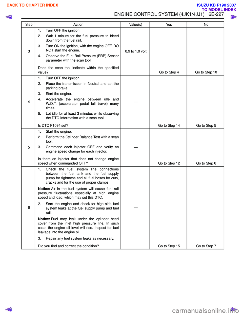
31. Turn OFF the ignition.
2. Wait 1 minute for the fuel pressure to bleed down from the fuel rail.
3. Turn ON the ignition, with the engine OFF. DO NOT start the engine.
4. Observe the Fuel Rail Pressure (FRP) Sensor parameter with the scan tool.
Does the scan tool indicate within the specified
value? 0.9 to 1.0 volt
Go to Step 4 Go to Step 10
4 1. Turn OFF the ignition.
2. Place the transmission in Neutral and set the parking brake.
3. Start the engine.
4. Accelerate the engine between idle and W.O.T. (accelerator pedal full travel) many
times.
5. Let idle for at least 3 minutes while observing the DTC Information with a scan tool.
Is DTC P1094 set? —
Go to Step 14 Go to Step 5
5 1. Start the engine.
2. Perform the Cylinder Balance Test with a scan tool.
3. Command each injector OFF and verify an engine speed change for each injector.
Is there an injector that does not change engine
speed when commanded OFF? —
Go to Step 12 Go to Step 6
6 1. Check the fuel system line connections
between the fuel tank and the fuel supply
pump for tightness and all fuel hoses for cuts,
cracks and for the use of proper clamps.
Notice: Air in the fuel system will cause fuel rail
pressure fluctuations especially at high engine
speed and load, which may set this DTC.
2. Start the engine and check for high side fuel system leaks at the fuel supply pump and fuel
rail.
Notice: Fuel may leak under the cylinder head
cover from the inlet high pressure line. In such
case, the engine oil level will rise. Inspect for fuel
leakage into the engine oil.
3. Repair any fuel system leaks as necessary.
Did you find and correct the condition? —
Go to Step 15 Go to Step 7
Step
Action Value(s)Yes No
BACK TO CHAPTER INDEX
TO MODEL INDEX
ISUZU KB P190 2007
Page 1949 of 6020
6E-332 ENGINE CONTROL SYSTEM (4JK1/4JJ1)
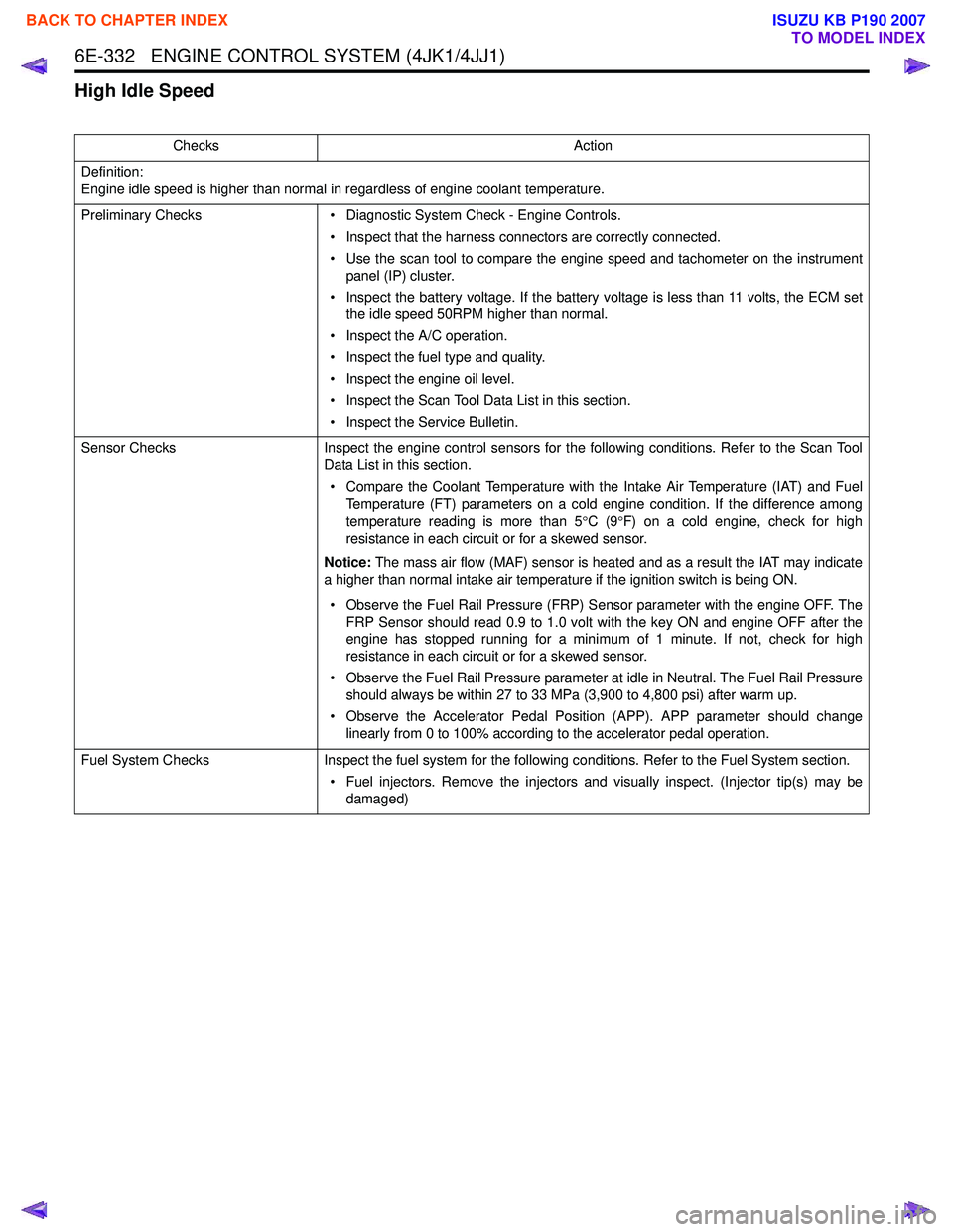
High Idle Speed
ChecksAction
Definition:
Engine idle speed is higher than normal in regardless of engine coolant temperature.
Preliminary Checks • Diagnostic System Check - Engine Controls.
• Inspect that the harness connectors are correctly connected.
• Use the scan tool to compare the engine speed and tachometer on the instrument panel (IP) cluster.
• Inspect the battery voltage. If the battery voltage is less than 11 volts, the ECM set the idle speed 50RPM higher than normal.
• Inspect the A/C operation.
• Inspect the fuel type and quality.
• Inspect the engine oil level.
• Inspect the Scan Tool Data List in this section.
• Inspect the Service Bulletin.
Sensor Checks Inspect the engine control sensors for the following conditions. Refer to the Scan Tool
Data List in this section.
• Compare the Coolant Temperature with the Intake Air Temperature (IAT) and Fuel Temperature (FT) parameters on a cold engine condition. If the difference among
temperature reading is more than 5 °C (9 °F) on a cold engine, check for high
resistance in each circuit or for a skewed sensor.
Notice: The mass air flow (MAF) sensor is heated and as a result the IAT may indicate
a higher than normal intake air temperature if the ignition switch is being ON.
• Observe the Fuel Rail Pressure (FRP) Sensor parameter with the engine OFF. The FRP Sensor should read 0.9 to 1.0 volt with the key ON and engine OFF after the
engine has stopped running for a minimum of 1 minute. If not, check for high
resistance in each circuit or for a skewed sensor.
• Observe the Fuel Rail Pressure parameter at idle in Neutral. The Fuel Rail Pressure should always be within 27 to 33 MPa (3,900 to 4,800 psi) after warm up.
• Observe the Accelerator Pedal Position (APP). APP parameter should change linearly from 0 to 100% according to the accelerator pedal operation.
Fuel System Checks Inspect the fuel system for the following conditions. Refer to the Fuel System section.
• Fuel injectors. Remove the injectors and visually inspect. (Injector tip(s) may be damaged)
BACK TO CHAPTER INDEX
TO MODEL INDEX
ISUZU KB P190 2007
Page 1953 of 6020
6E-336 ENGINE CONTROL SYSTEM (4JK1/4JJ1)
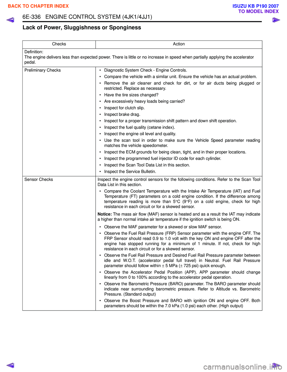
Lack of Power, Sluggishness or Sponginess
ChecksAction
Definition:
The engine delivers less than expected power. There is little or no increase in speed when partially applying the accelerator
pedal.
Preliminary Checks • Diagnostic System Check - Engine Controls.
• Compare the vehicle with a similar unit. Ensure the vehicle has an actual problem.
• Remove the air cleaner and check for dirt, or for air ducts being plugged or restricted. Replace as necessary.
• Have the tire sizes changed?
• Are excessively heavy loads being carried?
• Inspect for clutch slip.
• Inspect brake drag.
• Inspect for a proper transmission shift pattern and down shift operation.
• Inspect the fuel quality (cetane index).
• Inspect the engine oil level and quality.
• Use the scan tool in order to make sure the Vehicle Speed parameter reading matches the vehicle speedometer.
• Inspect the ECM grounds for being clean, tight, and in their proper locations.
• Inspect the programmed fuel injector ID code for each cylinder.
• Inspect the Scan Tool Data List in this section.
• Inspect the Service Bulletin.
Sensor Checks Inspect the engine control sensors for the following conditions. Refer to the Scan Tool
Data List in this section.
• Compare the Coolant Temperature with the Intake Air Temperature (IAT) and Fuel Temperature (FT) parameters on a cold engine condition. If the difference among
temperature reading is more than 5 °C (9 °F) on a cold engine, check for high
resistance in each circuit or for a skewed sensor.
Notice: The mass air flow (MAF) sensor is heated and as a result the IAT may indicate
a higher than normal intake air temperature if the ignition switch is being ON.
• Observe the MAF parameter for a skewed or slow MAF sensor.
• Observe the Fuel Rail Pressure (FRP) Sensor parameter with the engine OFF. The FRP Sensor should read 0.9 to 1.0 volt with the key ON and engine OFF after the
engine has stopped running for a minimum of 1 minute. If not, check for high
resistance in each circuit or for a skewed sensor.
• Observe the Fuel Rail Pressure and Desired Fuel Rail Pressure parameter between idle and W.O.T. (accelerator pedal full travel) in Neutral. Fuel Rail Pressure
parameter should follow within ± 5 MPa ( ± 725 psi) quick enough.
• Observe the Accelerator Pedal Position (APP). APP parameter should change linearly from 0 to 100% according to the accelerator pedal operation.
• Observe the Barometric Pressure (BARO) parameter. The BARO parameter should indicate near surrounding barometric pressure. Refer to Altitude vs. Barometric
Pressure. (Standard output)
• Observe the Boost Pressure and BARO with ignition ON and engine OFF. Both parameters should be within the 7.0 kPa (1.0 psi) each other. (High output)
BACK TO CHAPTER INDEX
TO MODEL INDEX
ISUZU KB P190 2007
Page 1955 of 6020
6E-338 ENGINE CONTROL SYSTEM (4JK1/4JJ1)
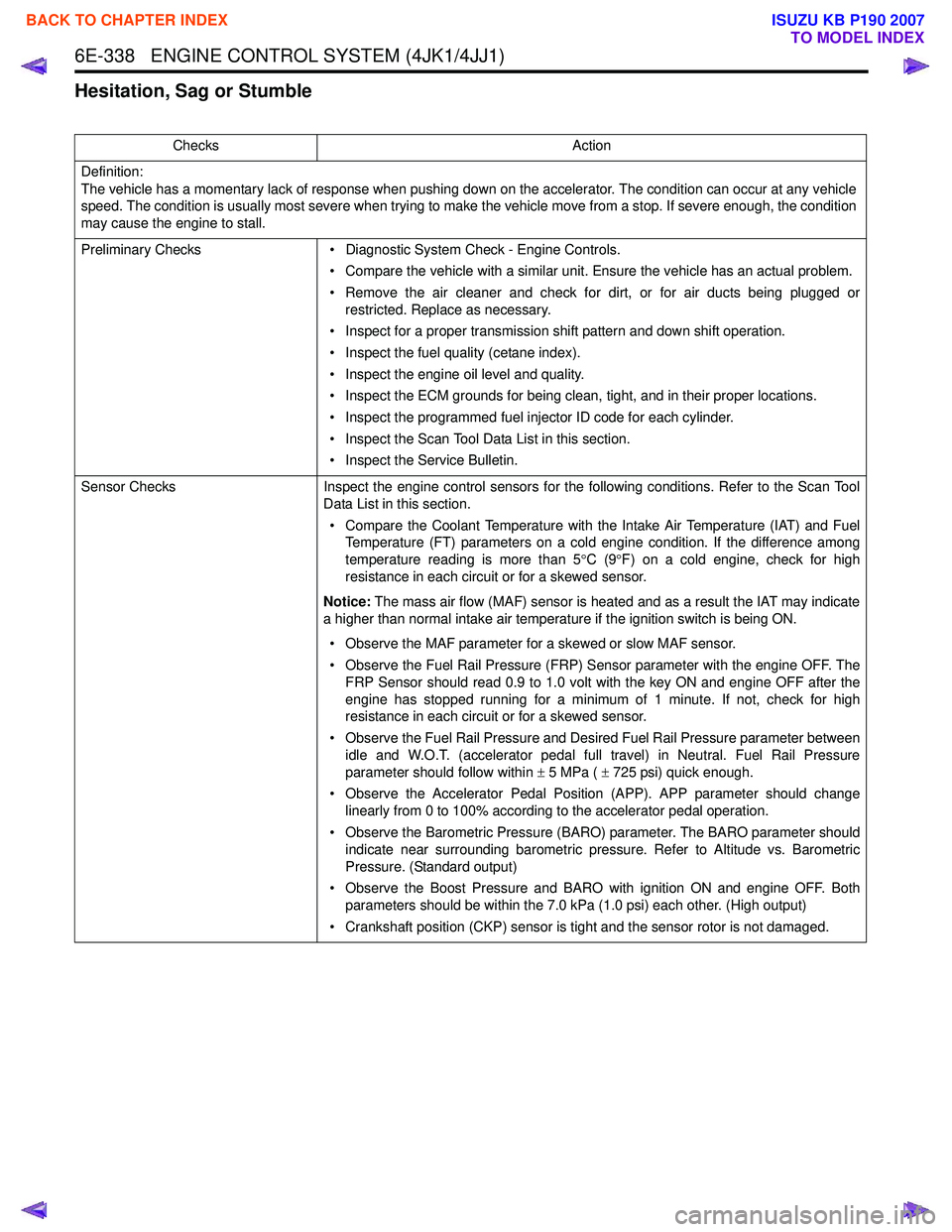
Hesitation, Sag or Stumble
ChecksAction
Definition:
The vehicle has a momentary lack of response when pushing down on the accelerator. The condition can occur at any vehicle
speed. The condition is usually most severe when trying to make the vehicle move from a stop. If severe enough, the condition
may cause the engine to stall.
Preliminary Checks • Diagnostic System Check - Engine Controls.
• Compare the vehicle with a similar unit. Ensure the vehicle has an actual problem.
• Remove the air cleaner and check for dirt, or for air ducts being plugged or restricted. Replace as necessary.
• Inspect for a proper transmission shift pattern and down shift operation.
• Inspect the fuel quality (cetane index).
• Inspect the engine oil level and quality.
• Inspect the ECM grounds for being clean, tight, and in their proper locations.
• Inspect the programmed fuel injector ID code for each cylinder.
• Inspect the Scan Tool Data List in this section.
• Inspect the Service Bulletin.
Sensor Checks Inspect the engine control sensors for the following conditions. Refer to the Scan Tool
Data List in this section.
• Compare the Coolant Temperature with the Intake Air Temperature (IAT) and Fuel Temperature (FT) parameters on a cold engine condition. If the difference among
temperature reading is more than 5 °C (9 °F) on a cold engine, check for high
resistance in each circuit or for a skewed sensor.
Notice: The mass air flow (MAF) sensor is heated and as a result the IAT may indicate
a higher than normal intake air temperature if the ignition switch is being ON.
• Observe the MAF parameter for a skewed or slow MAF sensor.
• Observe the Fuel Rail Pressure (FRP) Sensor parameter with the engine OFF. The FRP Sensor should read 0.9 to 1.0 volt with the key ON and engine OFF after the
engine has stopped running for a minimum of 1 minute. If not, check for high
resistance in each circuit or for a skewed sensor.
• Observe the Fuel Rail Pressure and Desired Fuel Rail Pressure parameter between idle and W.O.T. (accelerator pedal full travel) in Neutral. Fuel Rail Pressure
parameter should follow within ± 5 MPa ( ± 725 psi) quick enough.
• Observe the Accelerator Pedal Position (APP). APP parameter should change linearly from 0 to 100% according to the accelerator pedal operation.
• Observe the Barometric Pressure (BARO) parameter. The BARO parameter should indicate near surrounding barometric pressure. Refer to Altitude vs. Barometric
Pressure. (Standard output)
• Observe the Boost Pressure and BARO with ignition ON and engine OFF. Both parameters should be within the 7.0 kPa (1.0 psi) each other. (High output)
• Crankshaft position (CKP) sensor is tight and the sensor rotor is not damaged.
BACK TO CHAPTER INDEX
TO MODEL INDEX
ISUZU KB P190 2007
Page 1957 of 6020
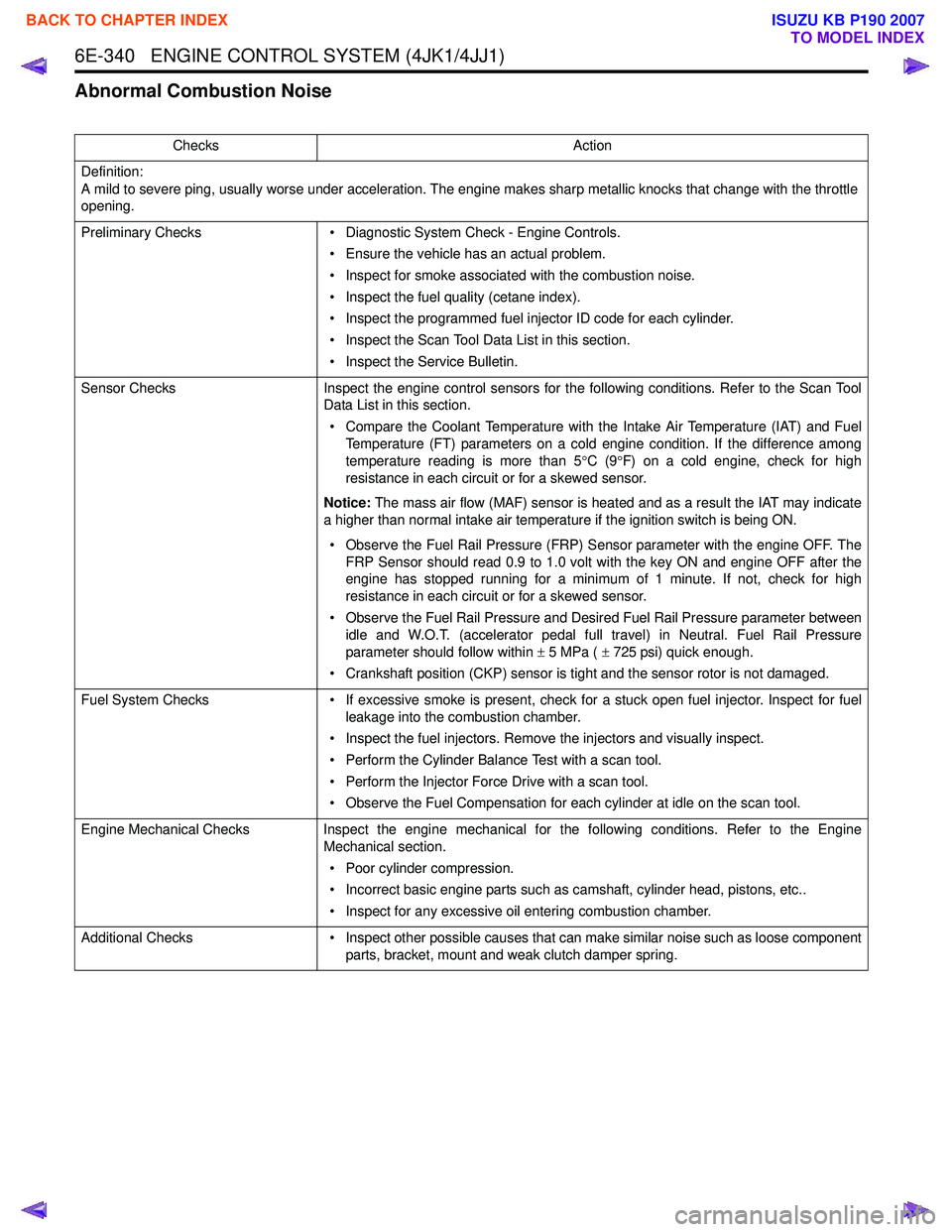
6E-340 ENGINE CONTROL SYSTEM (4JK1/4JJ1)
Abnormal Combustion Noise
ChecksAction
Definition:
A mild to severe ping, usually worse under acceleration. The engine makes sharp metallic knocks that change with the throttle
opening.
Preliminary Checks • Diagnostic System Check - Engine Controls.
• Ensure the vehicle has an actual problem.
• Inspect for smoke associated with the combustion noise.
• Inspect the fuel quality (cetane index).
• Inspect the programmed fuel injector ID code for each cylinder.
• Inspect the Scan Tool Data List in this section.
• Inspect the Service Bulletin.
Sensor Checks Inspect the engine control sensors for the following conditions. Refer to the Scan Tool
Data List in this section.
• Compare the Coolant Temperature with the Intake Air Temperature (IAT) and Fuel Temperature (FT) parameters on a cold engine condition. If the difference among
temperature reading is more than 5 °C (9 °F) on a cold engine, check for high
resistance in each circuit or for a skewed sensor.
Notice: The mass air flow (MAF) sensor is heated and as a result the IAT may indicate
a higher than normal intake air temperature if the ignition switch is being ON.
• Observe the Fuel Rail Pressure (FRP) Sensor parameter with the engine OFF. The FRP Sensor should read 0.9 to 1.0 volt with the key ON and engine OFF after the
engine has stopped running for a minimum of 1 minute. If not, check for high
resistance in each circuit or for a skewed sensor.
• Observe the Fuel Rail Pressure and Desired Fuel Rail Pressure parameter between idle and W.O.T. (accelerator pedal full travel) in Neutral. Fuel Rail Pressure
parameter should follow within ± 5 MPa ( ± 725 psi) quick enough.
• Crankshaft position (CKP) sensor is tight and the sensor rotor is not damaged.
Fuel System Checks • If excessive smoke is present, check for a stuck open fuel injector. Inspect for fuel
leakage into the combustion chamber.
• Inspect the fuel injectors. Remove the injectors and visually inspect.
• Perform the Cylinder Balance Test with a scan tool.
• Perform the Injector Force Drive with a scan tool.
• Observe the Fuel Compensation for each cylinder at idle on the scan tool.
Engine Mechanical Checks Inspect the engine mechanical for the following conditions. Refer to the Engine
Mechanical section.
• Poor cylinder compression.
• Incorrect basic engine parts such as camshaft, cylinder head, pistons, etc..
• Inspect for any excessive oil entering combustion chamber.
Additional Checks • Inspect other possible causes that can make similar noise such as loose component
parts, bracket, mount and weak clutch damper spring.
BACK TO CHAPTER INDEX
TO MODEL INDEX
ISUZU KB P190 2007
Page 1958 of 6020
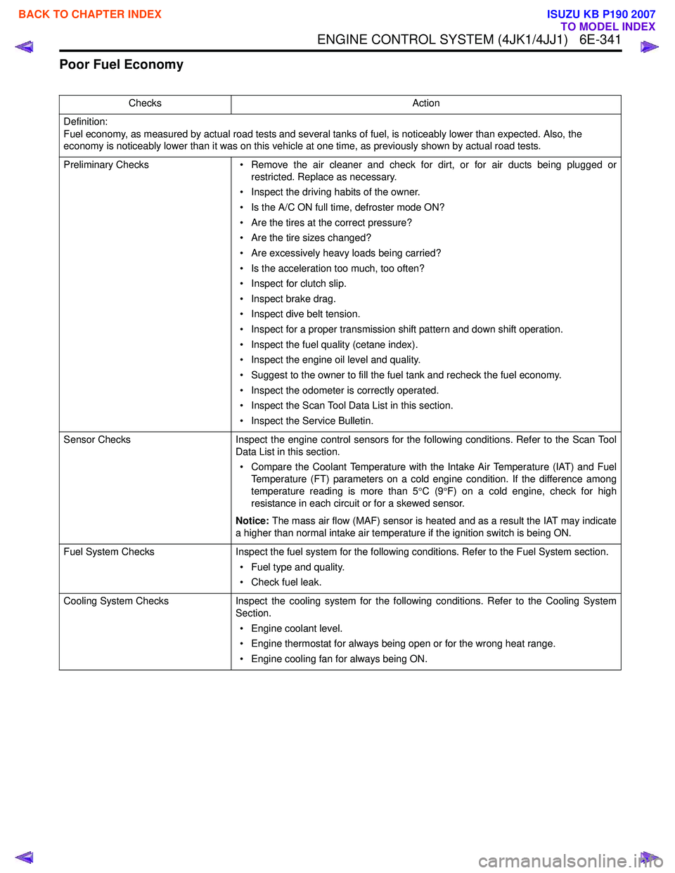
ENGINE CONTROL SYSTEM (4JK1/4JJ1) 6E-341
Poor Fuel Economy
ChecksAction
Definition:
Fuel economy, as measured by actual road tests and several tanks of fuel, is noticeably lower than expected. Also, the
economy is noticeably lower than it was on this vehicle at one time, as previously shown by actual road tests.
Preliminary Checks • Remove the air cleaner and check for dirt, or for air ducts being plugged or
restricted. Replace as necessary.
• Inspect the driving habits of the owner.
• Is the A/C ON full time, defroster mode ON?
• Are the tires at the correct pressure?
• Are the tire sizes changed?
• Are excessively heavy loads being carried?
• Is the acceleration too much, too often?
• Inspect for clutch slip.
• Inspect brake drag.
• Inspect dive belt tension.
• Inspect for a proper transmission shift pattern and down shift operation.
• Inspect the fuel quality (cetane index).
• Inspect the engine oil level and quality.
• Suggest to the owner to fill the fuel tank and recheck the fuel economy.
• Inspect the odometer is correctly operated.
• Inspect the Scan Tool Data List in this section.
• Inspect the Service Bulletin.
Sensor Checks Inspect the engine control sensors for the following conditions. Refer to the Scan Tool
Data List in this section.
• Compare the Coolant Temperature with the Intake Air Temperature (IAT) and Fuel Temperature (FT) parameters on a cold engine condition. If the difference among
temperature reading is more than 5 °C (9 °F) on a cold engine, check for high
resistance in each circuit or for a skewed sensor.
Notice: The mass air flow (MAF) sensor is heated and as a result the IAT may indicate
a higher than normal intake air temperature if the ignition switch is being ON.
Fuel System Checks Inspect the fuel system for the following conditions. Refer to the Fuel System section.
• Fuel type and quality.
• Check fuel leak.
Cooling System Checks Inspect the cooling system for the following conditions. Refer to the Cooling System
Section.
• Engine coolant level.
• Engine thermostat for always being open or for the wrong heat range.
• Engine cooling fan for always being ON.
BACK TO CHAPTER INDEX
TO MODEL INDEX
ISUZU KB P190 2007
Page 1962 of 6020
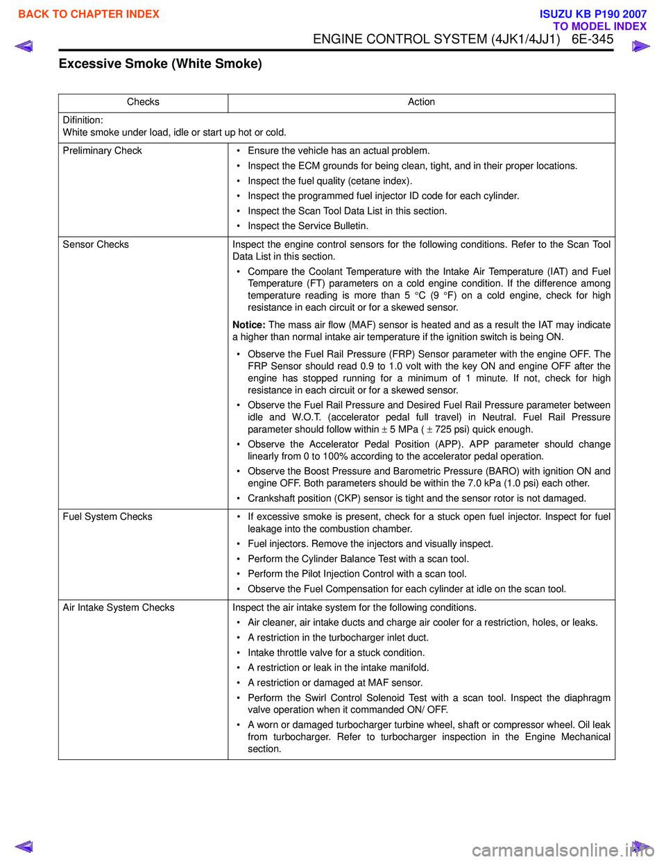
ENGINE CONTROL SYSTEM (4JK1/4JJ1) 6E-345
Excessive Smoke (White Smoke)
ChecksAction
Difinition:
White smoke under load, idle or start up hot or cold.
Preliminary Check • Ensure the vehicle has an actual problem.
• Inspect the ECM grounds for being clean, tight, and in their proper locations.
• Inspect the fuel quality (cetane index).
• Inspect the programmed fuel injector ID code for each cylinder.
• Inspect the Scan Tool Data List in this section.
• Inspect the Service Bulletin.
Sensor Checks Inspect the engine control sensors for the following conditions. Refer to the Scan Tool
Data List in this section.
• Compare the Coolant Temperature with the Intake Air Temperature (IAT) and Fuel Temperature (FT) parameters on a cold engine condition. If the difference among
temperature reading is more than 5 °C (9 °F) on a cold engine, check for high
resistance in each circuit or for a skewed sensor.
Notice: The mass air flow (MAF) sensor is heated and as a result the IAT may indicate
a higher than normal intake air temperature if the ignition switch is being ON.
• Observe the Fuel Rail Pressure (FRP) Sensor parameter with the engine OFF. The FRP Sensor should read 0.9 to 1.0 volt with the key ON and engine OFF after the
engine has stopped running for a minimum of 1 minute. If not, check for high
resistance in each circuit or for a skewed sensor.
• Observe the Fuel Rail Pressure and Desired Fuel Rail Pressure parameter between idle and W.O.T. (accelerator pedal full travel) in Neutral. Fuel Rail Pressure
parameter should follow within ± 5 MPa ( ± 725 psi) quick enough.
• Observe the Accelerator Pedal Position (APP). APP parameter should change linearly from 0 to 100% according to the accelerator pedal operation.
• Observe the Boost Pressure and Barometric Pressure (BARO) with ignition ON and engine OFF. Both parameters should be within the 7.0 kPa (1.0 psi) each other.
• Crankshaft position (CKP) sensor is tight and the sensor rotor is not damaged.
Fuel System Checks • If excessive smoke is present, check for a stuck open fuel injector. Inspect for fuel
leakage into the combustion chamber.
• Fuel injectors. Remove the injectors and visually inspect.
• Perform the Cylinder Balance Test with a scan tool.
• Perform the Pilot Injection Control with a scan tool.
• Observe the Fuel Compensation for each cylinder at idle on the scan tool.
Air Intake System Checks Inspect the air intake system for the following conditions.
• Air cleaner, air intake ducts and charge air cooler for a restriction, holes, or leaks.
• A restriction in the turbocharger inlet duct.
• Intake throttle valve for a stuck condition.
• A restriction or leak in the intake manifold.
• A restriction or damaged at MAF sensor.
• Perform the Swirl Control Solenoid Test with a scan tool. Inspect the diaphragm valve operation when it commanded ON/ OFF.
• A worn or damaged turbocharger turbine wheel, shaft or compressor wheel. Oil leak from turbocharger. Refer to turbocharger inspection in the Engine Mechanical
section.
BACK TO CHAPTER INDEX
TO MODEL INDEX
ISUZU KB P190 2007
Page 2008 of 6020
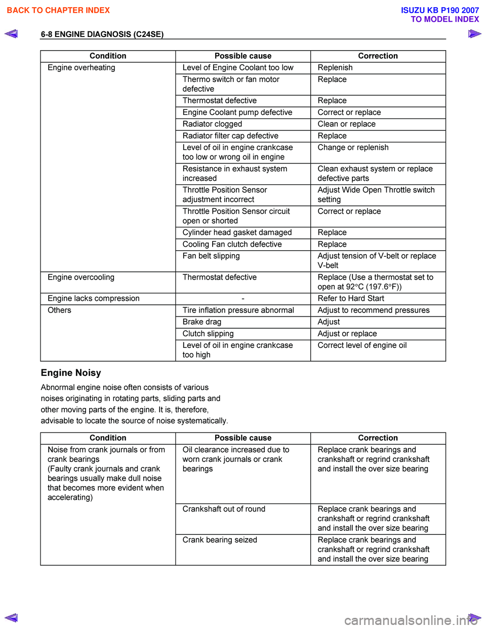
6-8 ENGINE DIAGNOSIS (C24SE)
Condition Possible cause Correction
Engine overheating Level of Engine Coolant too low Replenish
Thermo switch or fan motor
defective Replace
Thermostat
defective Replace
Engine Coolant pump defective Correct or replace
Radiator clogged Clean or replace
Radiator filter cap defective Replace
Level of oil in engine crankcase
too low or wrong oil in engine Change or replenish
Resistance in exhaust system
increased Clean exhaust system or replace
defective parts
Throttle Position Sensor
adjustment incorrect Adjust Wide Open Throttle switch
setting
Throttle Position Sensor circuit
open or shorted Correct or replace
Cylinder head gasket damaged Replace
Cooling Fan clutch defective Replace
Fan belt slipping Adjust tension of V-belt or replace
V-belt
Engine overcooling Thermostat defective Replace (Use a thermostat set to
open at 92 °C (197.6 °F))
Engine lacks compression - Refer to Hard Start
Others Tire inflation pressure abnormal Adjust to recommend pressures
Brake drag Adjust
Clutch slipping Adjust or replace
Level of oil in engine crankcase
too high Correct level of engine oil
Engine Noisy
Abnormal engine noise often consists of various
noises originating in rotating parts, sliding parts and
other moving parts of the engine. It is, therefore,
advisable to locate the source of noise systematically.
Condition Possible cause Correction
Noise from crank journals or from
crank bearings
(Faulty crank journals and crank
bearings usually make dull noise
that becomes more evident when
accelerating) Oil clearance increased due to
worn crank journals or crank
bearings Replace crank bearings and
crankshaft or regrind crankshaft
and install the over size bearing
Crankshaft out of round Replace crank bearings and
crankshaft or regrind crankshaft
and install the over size bearing
Crank bearing seized Replace crank bearings and
crankshaft or regrind crankshaft
and install the over size bearing
BACK TO CHAPTER INDEX
TO MODEL INDEX
ISUZU KB P190 2007