2007 ISUZU KB P190 oil change
[x] Cancel search: oil changePage 1305 of 6020
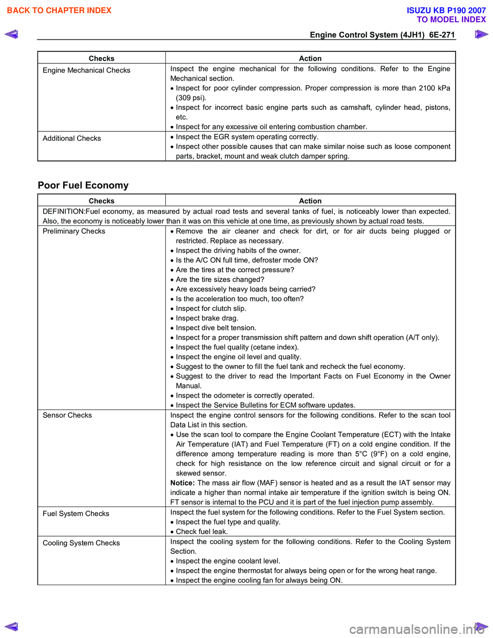
Engine Control System (4JH1) 6E-271
Checks Action
Engine Mechanical Checks Inspect the engine mechanical for the following conditions. Refer to the Engine
Mechanical section.
• Inspect for poor cylinder compression. Proper compression is more than 2100 kPa
(309 psi).
• Inspect for incorrect basic engine parts such as camshaft, cylinder head, pistons,
etc.
• Inspect for any excessive oil entering combustion chamber.
Additional Checks •
Inspect the EGR system operating correctly.
• Inspect other possible causes that can make similar noise such as loose component
parts, bracket, mount and weak clutch damper spring.
Poor Fuel Economy
Checks Action
DEFINITION:Fuel economy, as measured by actual road tests and several tanks of fuel, is noticeably lower than expected.
Also, the economy is noticeably lower than it was on this vehicle at one time, as previously shown by actual road tests.
Preliminary Checks • Remove the air cleaner and check for dirt, or for air ducts being plugged or
restricted. Replace as necessary.
• Inspect the driving habits of the owner.
• Is the A/C ON full time, defroster mode ON?
• Are the tires at the correct pressure?
• Are the tire sizes changed?
• Are excessively heavy loads being carried?
• Is the acceleration too much, too often?
• Inspect for clutch slip.
• Inspect brake drag.
• Inspect dive belt tension.
• Inspect for a proper transmission shift pattern and down shift operation (A/T only).
• Inspect the fuel quality (cetane index).
• Inspect the engine oil level and quality.
• Suggest to the owner to fill the fuel tank and recheck the fuel economy.
• Suggest to the driver to read the Important Facts on Fuel Economy in the Owner
Manual.
• Inspect the odometer is correctly operated.
• Inspect the Service Bulletins for ECM software updates.
Sensor Checks Inspect the engine control sensors for the following conditions. Refer to the scan tool
Data List in this section.
• Use the scan tool to compare the Engine Coolant Temperature (ECT) with the Intake
Air Temperature (IAT) and Fuel Temperature (FT) on a cold engine condition. If the
difference among temperature reading is more than 5°C (9°F) on a cold engine,
check for high resistance on the low reference circuit and signal circuit or for a
skewed sensor.
Notice: The mass air flow (MAF) sensor is heated and as a result the IAT sensor may
indicate a higher than normal intake air temperature if the ignition switch is being ON.
FT sensor is internal to the PCU and it is part of the fuel injection pump assembly.
Fuel System Checks Inspect the fuel system for the following conditions. Refer to the Fuel System section.
• Inspect the fuel type and quality.
• Check fuel leak.
Cooling System Checks Inspect the cooling system for the following conditions. Refer to the Cooling System
Section.
• Inspect the engine coolant level.
• Inspect the engine thermostat for always being open or for the wrong heat range.
• Inspect the engine cooling fan for always being ON.
BACK TO CHAPTER INDEX
TO MODEL INDEX
ISUZU KB P190 2007
Page 1306 of 6020
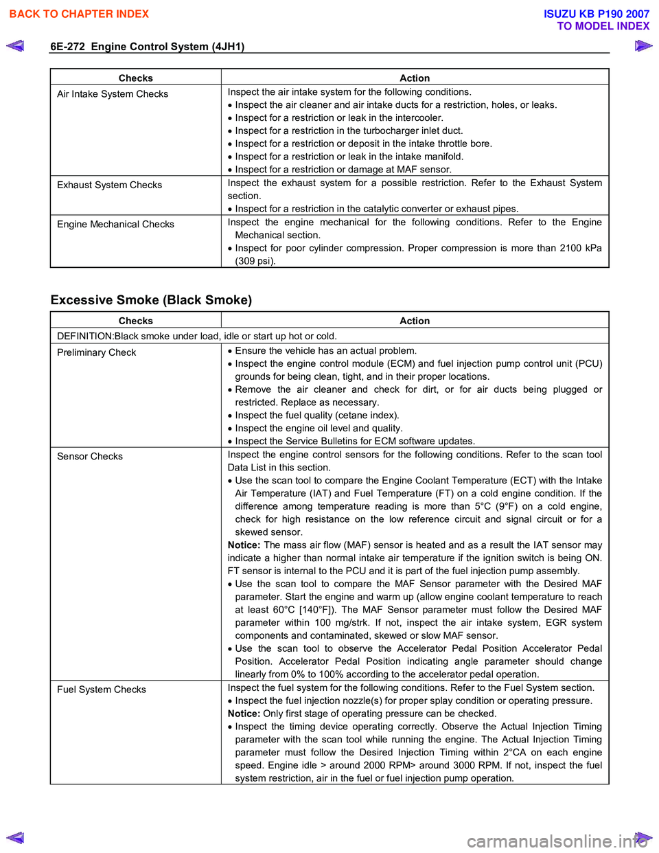
6E-272 Engine Control System (4JH1)
Checks Action
Air Intake System Checks Inspect the air intake system for the following conditions.
• Inspect the air cleaner and air intake ducts for a restriction, holes, or leaks.
• Inspect for a restriction or leak in the intercooler.
• Inspect for a restriction in the turbocharger inlet duct.
• Inspect for a restriction or deposit in the intake throttle bore.
• Inspect for a restriction or leak in the intake manifold.
• Inspect for a restriction or damage at MAF sensor.
Exhaust System Checks Inspect the exhaust system for a possible restriction. Refer to the Exhaust System
section.
• Inspect for a restriction in the catalytic converter or exhaust pipes.
Engine Mechanical Checks Inspect the engine mechanical for the following conditions. Refer to the Engine
Mechanical section.
• Inspect for poor cylinder compression. Proper compression is more than 2100 kPa
(309 psi).
Excessive Smoke (Black Smoke)
Checks Action
DEFINITION:Black smoke under load, idle or start up hot or cold.
Preliminary Check •
Ensure the vehicle has an actual problem.
• Inspect the engine control module (ECM) and fuel injection pump control unit (PCU)
grounds for being clean, tight, and in their proper locations.
• Remove the air cleaner and check for dirt, or for air ducts being plugged or
restricted. Replace as necessary.
• Inspect the fuel quality (cetane index).
• Inspect the engine oil level and quality.
• Inspect the Service Bulletins for ECM software updates.
Sensor Checks Inspect the engine control sensors for the following conditions. Refer to the scan tool
Data List in this section.
• Use the scan tool to compare the Engine Coolant Temperature (ECT) with the Intake
Air Temperature (IAT) and Fuel Temperature (FT) on a cold engine condition. If the
difference among temperature reading is more than 5°C (9°F) on a cold engine,
check for high resistance on the low reference circuit and signal circuit or for a
skewed sensor.
Notice: The mass air flow (MAF) sensor is heated and as a result the IAT sensor may
indicate a higher than normal intake air temperature if the ignition switch is being ON.
FT sensor is internal to the PCU and it is part of the fuel injection pump assembly.
• Use the scan tool to compare the MAF Sensor parameter with the Desired MAF
parameter. Start the engine and warm up (allow engine coolant temperature to reach
at least 60°C [140°F]). The MAF Sensor parameter must follow the Desired MAF
parameter within 100 mg/strk. If not, inspect the air intake system, EGR system
components and contaminated, skewed or slow MAF sensor.
• Use the scan tool to observe the Accelerator Pedal Position Accelerator Pedal
Position. Accelerator Pedal Position indicating angle parameter should change
linearly from 0% to 100% according to the accelerator pedal operation.
Fuel System Checks Inspect the fuel system for the following conditions. Refer to the Fuel System section.
• Inspect the fuel injection nozzle(s) for proper splay condition or operating pressure.
Notice: Only first stage of operating pressure can be checked.
• Inspect the timing device operating correctly. Observe the Actual Injection Timing
parameter with the scan tool while running the engine. The Actual Injection Timing
parameter must follow the Desired Injection Timing within 2°CA on each engine
speed. Engine idle > around 2000 RPM> around 3000 RPM. If not, inspect the fuel
system restriction, air in the fuel or fuel injection pump operation.
BACK TO CHAPTER INDEX
TO MODEL INDEX
ISUZU KB P190 2007
Page 1372 of 6020
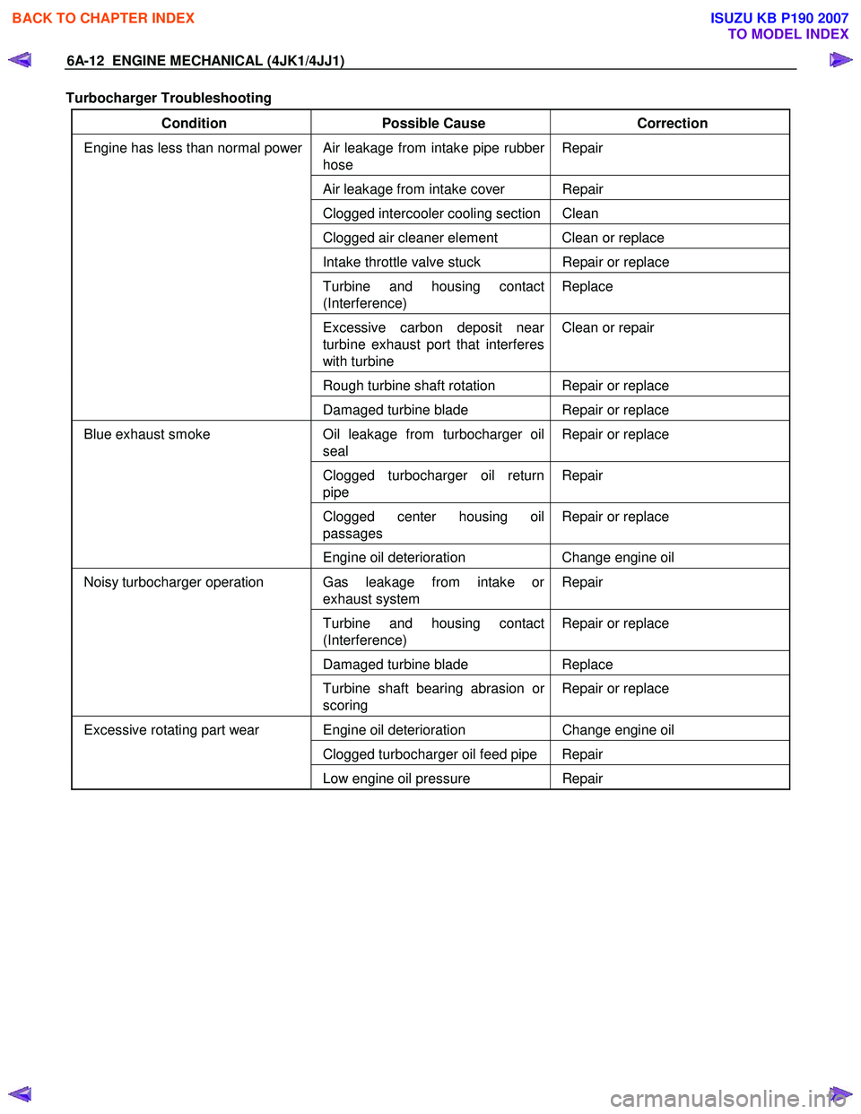
6A-12 ENGINE MECHANICAL (4JK1/4JJ1)
Turbocharger Troubleshooting
Condition Possible Cause Correction
Air leakage from intake pipe rubber
hose Repair
Air leakage from intake cover Repair
Clogged intercooler cooling section Clean
Clogged air cleaner element Clean or replace
Intake throttle valve stuck
Repair or replace
Turbine and housing contact
(Interference) Replace
Excessive carbon deposit near
turbine exhaust port that interferes
with turbine Clean or repair
Rough turbine shaft rotation Repair or replace
Engine has less than normal power
Damaged turbine blade Repair or replace
Oil leakage from turbocharger oil
seal Repair or replace
Clogged turbocharger oil return
pipe Repair
Clogged center housing oil
passages Repair or replace
Blue exhaust smoke
Engine oil deterioration Change engine oil
Gas leakage from intake or
exhaust system Repair
Turbine and housing contact
(Interference) Repair or replace
Damaged turbine blade
Replace
Noisy turbocharger operation
Turbine shaft bearing abrasion or
scoring Repair or replace
Engine oil deterioration
Change engine oil
Clogged turbocharger oil feed pipe Repair
Excessive rotating part wear
Low engine oil pressure Repair
BACK TO CHAPTER INDEX
TO MODEL INDEX
ISUZU KB P190 2007
Page 1529 of 6020
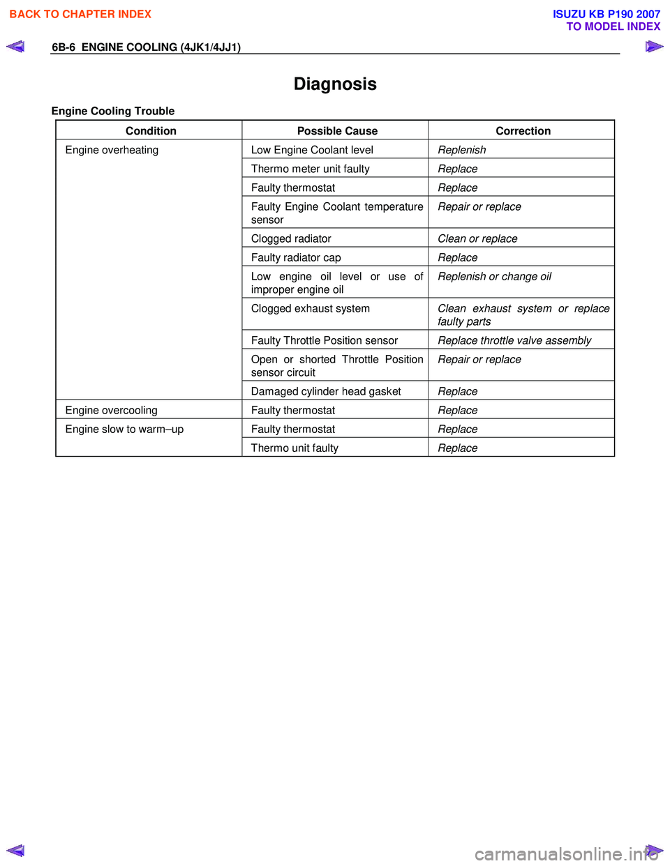
6B-6 ENGINE COOLING (4JK1/4JJ1)
Diagnosis
Engine Cooling Trouble
Condition Possible Cause Correction
Low Engine Coolant level Replenish
Thermo meter unit faulty Replace
Faulty thermostat Replace
Faulty Engine Coolant temperature
sensor Repair or replace
Clogged radiator
Clean or replace
Faulty radiator cap Replace
Low engine oil level or use of
improper engine oil Replenish or change oil
Clogged exhaust system
Clean exhaust system or replace
faulty parts
Faulty Throttle Position sensor Replace throttle valve assembly
Open or shorted Throttle Position
sensor circuit Repair or replace
Engine overheating
Damaged cylinder head gasket Replace
Engine overcooling Faulty thermostat Replace
Faulty thermostat Replace Engine slow to warm–up
Thermo unit faulty Replace
BACK TO CHAPTER INDEX
TO MODEL INDEX
ISUZU KB P190 2007
Page 1530 of 6020
ENGINE COOLING (4JK1/4JJ1) 6B-7
Draining and Refilling Cooling System
Before draining the cooling system, inspect the system
and perform any necessary service to ensure that it is
clean, does not leak and is in proper working order.
The engine coolant (EC) level should be between the
“MIN" and “MAX" lines of the reserve tank when the
engine is cold. If low, check for leakage and add EC up
to the “MAX" line.
There should not be any excessive deposit of rust o
r
scales around the radiator cap or radiator filler hole, and
the EC should also be free from oil.
Replace the EC if excessively dirty.
1. Remove the radiator skid plate.
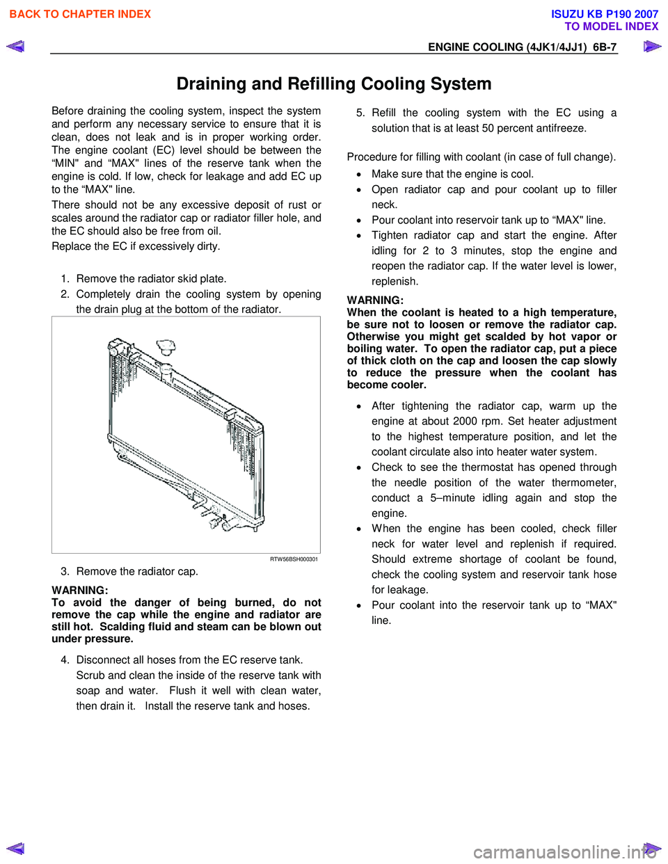
2. Completely drain the cooling system by opening the drain plug at the bottom of the radiator.
RTW 56BSH000301
3. Remove the radiator cap.
WARNING:
To avoid the danger of being burned, do not
remove the cap while the engine and radiator are
still hot. Scalding fluid and steam can be blown out
under pressure.
4. Disconnect all hoses from the EC reserve tank.
Scrub and clean the inside of the reserve tank with soap and water. Flush it well with clean water,
then drain it. Install the reserve tank and hoses.
5. Refill the cooling system with the EC using a
solution that is at least 50 percent antifreeze.
Procedure for filling with coolant (in case of full change).
• Make sure that the engine is cool.
• Open radiator cap and pour coolant up to fille
r
neck.
• Pour coolant into reservoir tank up to “MAX" line.
• Tighten radiator cap and start the engine. Afte
r
idling for 2 to 3 minutes, stop the engine and
reopen the radiator cap. If the water level is lower,
replenish.
WARNING:
When the coolant is heated to a high temperature,
be sure not to loosen or remove the radiator cap.
Otherwise you might get scalded by hot vapor o
r
boiling water. To open the radiator cap, put a piece
of thick cloth on the cap and loosen the cap slowly
to reduce the pressure when the coolant has
become cooler.
• After tightening the radiator cap, warm up the
engine at about 2000 rpm. Set heater adjustment
to the highest temperature position, and let the
coolant circulate also into heater water system.
• Check to see the thermostat has opened through
the needle position of the water thermometer,
conduct a 5–minute idling again and stop the
engine.
• W hen the engine has been cooled, check fille
r
neck for water level and replenish if required.
Should extreme shortage of coolant be found,
check the cooling system and reservoir tank hose
for leakage.
• Pour coolant into the reservoir tank up to “MAX"
line.
BACK TO CHAPTER INDEX
TO MODEL INDEX
ISUZU KB P190 2007
Page 1539 of 6020
6B-16 ENGINE COOLING (4JK1/4JJ1)
Installation
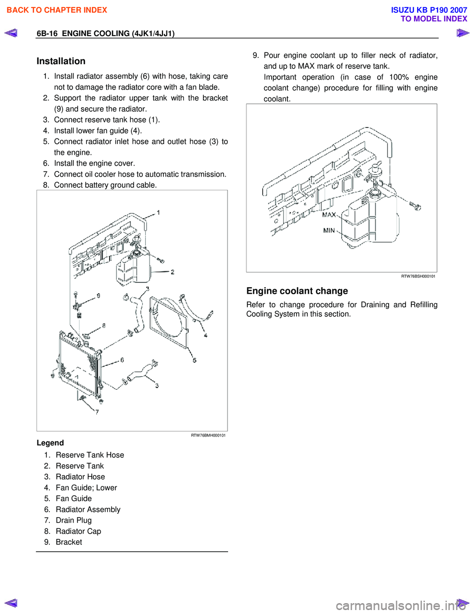
1. Install radiator assembly (6) with hose, taking care
not to damage the radiator core with a fan blade.
2. Support the radiator upper tank with the bracket (9) and secure the radiator.
3. Connect reserve tank hose (1).
4. Install lower fan guide (4).
5. Connect radiator inlet hose and outlet hose (3) to the engine.
6. Install the engine cover.
7. Connect oil cooler hose to automatic transmission.
8. Connect battery ground cable.
RTW 76BMH000101
Legend
1. Reserve Tank Hose
2. Reserve Tank
3. Radiator Hose
4. Fan Guide; Lower
5. Fan Guide
6. Radiator Assembly
7. Drain Plug
8. Radiator Cap
9. Bracket
9. Pour engine coolant up to filler neck of radiator,
and up to MAX mark of reserve tank.
Important operation (in case of 100% engine coolant change) procedure for filling with engine
coolant.
RTW 76BSH000101
Engine coolant change
Refer to change procedure for Draining and Refilling
Cooling System in this section.
BACK TO CHAPTER INDEX
TO MODEL INDEX
ISUZU KB P190 2007
Page 1692 of 6020
ENGINE CONTROL SYSTEM (4JK1/4JJ1) 6E-75
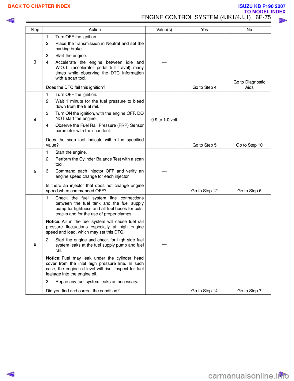
31. Turn OFF the ignition.
2. Place the transmission in Neutral and set the parking brake.
3. Start the engine.
4. Accelerate the engine between idle and W.O.T. (accelerator pedal full travel) many
times while observing the DTC Information
with a scan tool.
Does the DTC fail this ignition? —
Go to Step 4 Go to Diagnostic
Aids
4 1. Turn OFF the ignition.
2. Wait 1 minute for the fuel pressure to bleed down from the fuel rail.
3. Turn ON the ignition, with the engine OFF. DO NOT start the engine.
4. Observe the Fuel Rail Pressure (FRP) Sensor parameter with the scan tool.
Does the scan tool indicate within the specified
value? 0.9 to 1.0 volt
Go to Step 5 Go to Step 10
5 1. Start the engine.
2. Perform the Cylinder Balance Test with a scan tool.
3. Command each injector OFF and verify an engine speed change for each injector.
Is there an injector that does not change engine
speed when commanded OFF? —
Go to Step 12 Go to Step 6
6 1. Check the fuel system line connections
between the fuel tank and the fuel supply
pump for tightness and all fuel hoses for cuts,
cracks and for the use of proper clamps.
Notice: Air in the fuel system will cause fuel rail
pressure fluctuations especially at high engine
speed and load, which may set this DTC.
2. Start the engine and check for high side fuel system leaks at the fuel supply pump and fuel
rail.
Notice: Fuel may leak under the cylinder head
cover from the inlet high pressure line. In such
case, the engine oil level will rise. Inspect for fuel
leakage into the engine oil.
3. Repair any fuel system leaks as necessary.
Did you find and correct the condition? —
Go to Step 14 Go to Step 7
Step
Action Value(s)Yes No
BACK TO CHAPTER INDEX
TO MODEL INDEX
ISUZU KB P190 2007
Page 1697 of 6020
6E-80 ENGINE CONTROL SYSTEM (4JK1/4JJ1)
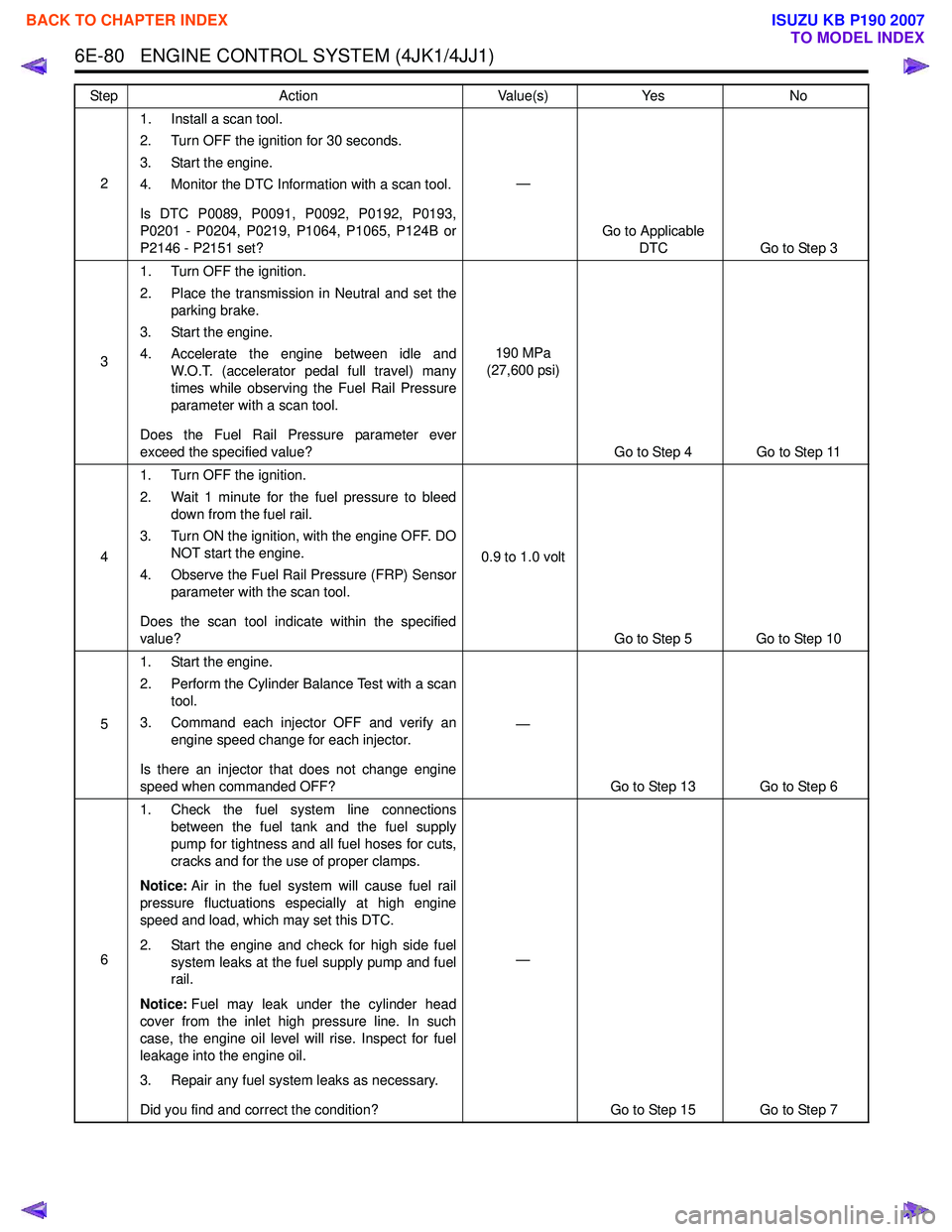
21. Install a scan tool.
2. Turn OFF the ignition for 30 seconds.
3. Start the engine.
4. Monitor the DTC Information with a scan tool.
Is DTC P0089, P0091, P0092, P0192, P0193,
P0201 - P0204, P0219, P1064, P1065, P124B or
P2146 - P2151 set? —
Go to Applicable DTC Go to Step 3
3 1. Turn OFF the ignition.
2. Place the transmission in Neutral and set the parking brake.
3. Start the engine.
4. Accelerate the engine between idle and W.O.T. (accelerator pedal full travel) many
times while observing the Fuel Rail Pressure
parameter with a scan tool.
Does the Fuel Rail Pressure parameter ever
exceed the specified value? 190 MPa
(27,600 psi)
Go to Step 4 Go to Step 11
4 1. Turn OFF the ignition.
2. Wait 1 minute for the fuel pressure to bleed down from the fuel rail.
3. Turn ON the ignition, with the engine OFF. DO NOT start the engine.
4. Observe the Fuel Rail Pressure (FRP) Sensor parameter with the scan tool.
Does the scan tool indicate within the specified
value? 0.9 to 1.0 volt
Go to Step 5 Go to Step 10
5 1. Start the engine.
2. Perform the Cylinder Balance Test with a scan tool.
3. Command each injector OFF and verify an engine speed change for each injector.
Is there an injector that does not change engine
speed when commanded OFF? —
Go to Step 13 Go to Step 6
6 1. Check the fuel system line connections
between the fuel tank and the fuel supply
pump for tightness and all fuel hoses for cuts,
cracks and for the use of proper clamps.
Notice: Air in the fuel system will cause fuel rail
pressure fluctuations especially at high engine
speed and load, which may set this DTC.
2. Start the engine and check for high side fuel system leaks at the fuel supply pump and fuel
rail.
Notice: Fuel may leak under the cylinder head
cover from the inlet high pressure line. In such
case, the engine oil level will rise. Inspect for fuel
leakage into the engine oil.
3. Repair any fuel system leaks as necessary.
Did you find and correct the condition? —
Go to Step 15 Go to Step 7
Step
Action Value(s)Yes No
BACK TO CHAPTER INDEX
TO MODEL INDEX
ISUZU KB P190 2007