2007 ISUZU KB P190 oil change
[x] Cancel search: oil changePage 3474 of 6020
Engine Management – V6 – Diagnostics Page 6C1-2–196
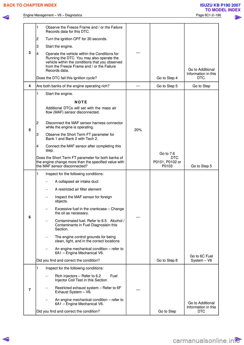
3 1 Observe the Freeze Frame and / or the Failure
Records data for this DTC.
2 Turn the ignition OFF for 30 seconds.
3 Start the engine.
4 Operate the vehicle within the Conditions for Running the DTC. You may also operate the
vehicle within the conditions that you observed
from the Freeze Frame and / or the Failure
Records data.
Does the DTC fail this ignition cycle? —
Go to Step 4 Go to Additional
Information in this DTC.
4 Are both banks of the engine operating rich? —
Go to Step 5 Go to Step
5 1 Start the engine.
NOTE
Additional DTCs will set with the mass air
flow (MAF) sensor disconnected.
2 Disconnect the MAF sensor harness connector while the engine is operating.
3 Observe the Short Term FT parameter for Bank 1 and Bank 2 with Tech 2.
4 Connect the MAF sensor after completing this step.
Does the Short Term FT parameter for both banks of
the engine change more than the specified value with
the MAF sensor disconnected? 20%
Go to 7.6
DTC
P0101, P0102 or P0103 Go to Step 5
6 1 Inspect for the following conditions:
− A collapsed air intake duct
− A restricted air filter element
− Inspect the MAF sensor for foreign
objects.
− Excessive fuel in the crankcase – Change
the oil as necessary.
− Contaminated fuel. Refer to 6.5 Alcohol /
Contaminants in Fuel Diagnosisin this
Section.
− The engine control grounds for being
clean, tight, and in the correct locations
− An engine mechanical condition – refer to
6A1 – Engine Mechanical V6.
Did you find and correct the condition? —
Go to Step 8 Go to 6C Fuel
System – V6
7 1 Inspect for the following conditions:
− Rich injectors – Refer to 6.2 Fuel
Injector Coil Test in this Section
− Restricted exhaust system – Refer to 6F
Exhaust System – V6.
− An engine mechanical condition – refer to
6A1 – Engine Mechanical V6.
Did you find and correct the condition? —
Go to Step Go to Additional
Information in this DTC
BACK TO CHAPTER INDEX
TO MODEL INDEX
ISUZU KB P190 2007
Page 3519 of 6020
Engine Management – V6 – Diagnostics Page 6C1-2–241
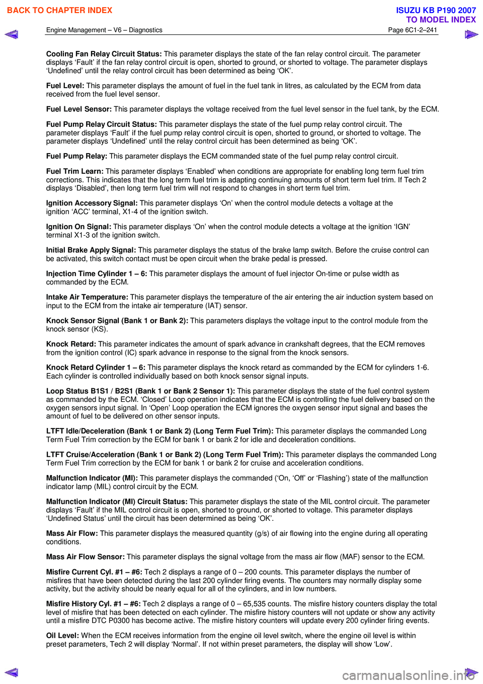
Cooling Fan Relay Circuit Status: This parameter displays the state of the fan relay control circuit. The parameter
displays ‘Fault’ if the fan relay control circuit is open, shorted to ground, or shorted to voltage. The parameter displays
‘Undefined’ until the relay control circuit has been determined as being ‘OK’.
Fuel Level: This parameter displays the amount of fuel in the fuel tank in litres, as calculated by the ECM from data
received from the fuel level sensor.
Fuel Level Sensor: This parameter displays the voltage received from the fuel level sensor in the fuel tank, by the ECM.
Fuel Pump Relay Circuit Status: This parameter displays the state of the fuel pump relay control circuit. The
parameter displays ‘Fault’ if the fuel pump relay control circuit is open, shorted to ground, or shorted to voltage. The
parameter displays ‘Undefined’ until the relay control circuit has been determined as being ‘OK’.
Fuel Pump Relay: This parameter displays the ECM commanded state of the fuel pump relay control circuit.
Fuel Trim Learn: This parameter displays ‘Enabled’ when conditions are appropriate for enabling long term fuel trim
corrections. This indicates that the long term fuel trim is adapting continuing amounts of short term fuel trim. If Tech 2
displays ‘Disabled’, then long term fuel trim will not respond to changes in short term fuel trim.
Ignition Accessory Signal: This parameter displays ‘On’ when the control module detects a voltage at the
ignition ‘ACC’ terminal, X1-4 of the ignition switch.
Ignition On Signal: This parameter displays ‘On’ when the control module detects a voltage at the ignition ‘IGN’
terminal X1-3 of the ignition switch.
Initial Brake Apply Signal: This parameter displays the status of the brake lamp switch. Before the cruise control can
be activated, this switch contact must be open circuit when the brake pedal is pressed.
Injection Time Cylinder 1 – 6: This parameter displays the amount of fuel injector On-time or pulse width as
commanded by the ECM.
Intake Air Temperature: This parameter displays the temperature of the air entering the air induction system based on
input to the ECM from the intake air temperature (IAT) sensor.
Knock Sensor Signal (Bank 1 or Bank 2): This parameters displays the voltage input to the control module from the
knock sensor (KS).
Knock Retard: This parameter indicates the amount of spark advance in crankshaft degrees, that the ECM removes
from the ignition control (IC) spark advance in response to the signal from the knock sensors.
Knock Retard Cylinder 1 – 6: This parameter displays the knock retard as commanded by the ECM for cylinders 1-6.
Each cylinder is controlled individually based on both knock sensor signal inputs.
Loop Status B1S1 / B2S1 (Bank 1 or Bank 2 Sensor 1): This parameter displays the state of the fuel control system
as commanded by the ECM. ‘Closed’ Loop operation indicates that the ECM is controlling the fuel delivery based on the
oxygen sensors input signal. In ‘Open’ Loop operation the ECM ignores the oxygen sensor input signal and bases the
amount of fuel to be delivered on other sensor inputs.
LTFT Idle/Deceleration (Bank 1 or Bank 2) (Long Term Fuel Trim): This parameter displays the commanded Long
Term Fuel Trim correction by the ECM for bank 1 or bank 2 for idle and deceleration conditions.
LTFT Cruise/Acceleration (Bank 1 or Bank 2) (Long Term Fuel Trim): This parameter displays the commanded Long
Term Fuel Trim correction by the ECM for bank 1 or bank 2 for cruise and acceleration conditions.
Malfunction Indicator (MI): This parameter displays the commanded (‘On, ‘Off’ or ‘Flashing’) state of the malfunction
indicator lamp (MIL) control circuit by the ECM.
Malfunction Indicator (MI) Circuit Status: This parameter displays the state of the MIL control circuit. The parameter
displays ‘Fault’ if the MIL control circuit is open, shorted to ground, or shorted to voltage. This parameter displays
‘Undefined Status’ until the circuit has been determined as being ‘OK’.
Mass Air Flow: This parameter displays the measured quantity (g/s) of air flowing into the engine during all operating
conditions.
Mass Air Flow Sensor: This parameter displays the signal voltage from the mass air flow (MAF) sensor to the ECM.
Misfire Current Cyl. #1 – #6: Tech 2 displays a range of 0 – 200 counts. This parameter displays the number of
misfires that have been detected during the last 200 cylinder firing events. The counters may normally display some
activity, but the activity should be nearly equal for all of the cylinders, and in low numbers.
Misfire History Cyl. #1 – #6: Tech 2 displays a range of 0 – 65,535 counts. The misfire history counters display the total
level of misfire that has been detected on each cylinder. The misfire history counters will not update or show any activity
until a misfire DTC P0300 has become active. The misfire history counters will update every 200 cylinder firing events.
Oil Level: W hen the ECM receives information from the engine oil level switch, where the engine oil level is within
preset parameters, Tech 2 will display ‘Normal’. If not within preset parameters, the display will show ‘Low’.
BACK TO CHAPTER INDEX
TO MODEL INDEX
ISUZU KB P190 2007
Page 3520 of 6020
Engine Management – V6 – Diagnostics Page 6C1-2–242
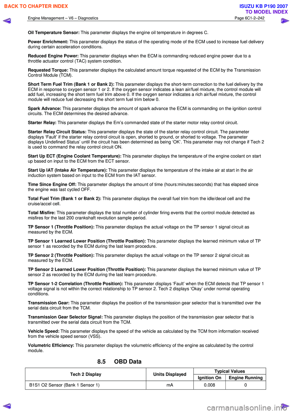
Oil Temperature Sensor: This parameter displays the engine oil temperature in degrees C.
Power Enrichment: This parameter displays the status of the operating mode of the ECM used to increase fuel delivery
during certain acceleration conditions.
Reduced Engine Power: This parameter displays when the ECM is commanding reduced engine power due to a
throttle actuator control (TAC) system condition.
Requested Torque: This parameter displays the calculated amount torque requested of the ECM by the Transmission
Control Module (TCM).
Short Term Fuel Trim (Bank 1 or Bank 2): This parameter displays the short-term correction to the fuel delivery by the
ECM in response to oxygen sensor 1 or 2. If the oxygen sensor indicates a lean air/fuel mixture, the control module will
add fuel, increasing the short term fuel trim above 0. If the oxygen sensor indicates a rich air/fuel mixture, the control
module will reduce fuel decreasing the short term fuel trim below 0.
Spark Advance: This parameter displays the amount of spark advance the ECM is commanding on the ignition control
circuits. The ECM determines the desired advance.
Starter Relay: This parameter displays the Em’s commanded state of the starter motor relay control circuit.
Starter Relay Circuit Status: This parameter displays the state of the starter relay control circuit. The parameter
displays ‘Fault’ if the starter relay control circuit is open, shorted to ground, or shorted to voltage. The parameter
displays Undefined Status’ until the circuit has been determined as being ‘OK’. This parameter may not change if Tech 2
is used to command the relay control circuit ON.
Start Up ECT (Engine Coolant Temperature): This parameter displays the temperature of the engine coolant on start
up based on input to the ECM from the ECT sensor.
Start Up IAT (Intake Air Temperature): This parameter displays the temperature of the intake air at start in the air
induction system based on input to the ECM from the IAT sensor.
Time Since Engine Off: This parameter displays the amount of time (hours:minutes:seconds) that has elapsed since
the engine was last cycled OFF.
Total Fuel Trim (Bank 1 or Bank 2): This parameter displays the overall fuel trim from the idle/decel cell and the
cruise/accel cell.
Total Misfire: This parameter displays the total number of cylinder firing events that the control module detected as
misfires for the last 200 crankshaft revolution sample period.
TP Sensor 1 (Throttle Position): This parameter displays the actual voltage on the TP sensor 1 signal circuit as
measured by the ECM.
TP Sensor 1 Learned Lower Position (Throttle Position): This parameter displays the learned minimum value of TP
sensor 1 as recorded by the ECM during the last learn procedure.
TP Sensor 2 (Throttle Position): This parameter displays the actual voltage on the TP sensor 2 signal circuit as
measured by the ECM.
TP Sensor 2 Learned Lower Position (Throttle Position): This parameter displays the learned minimum value of TP
sensor 2 as recorded by the ECM during the last learn procedure.
TP Sensor 1-2 Correlation (Throttle Position): This parameter displays ‘Fault’ when the ECM detects that TP sensor 1
voltage signal is not within the correct relationship to TP sensor 2. Tech 2 displays ‘Okay’ under normal operating
conditions.
Transmission Gear: This parameter displays the position of the transmission gear selector that is transmitted over the
serial data circuit from the TCM.
Transmission Gear Selector Signal: This parameter displays the position of the transmission gear selector that is
transmitted over the serial data circuit from the TCM.
Vehicle Speed: This parameter displays the speed of the vehicle as calculated by the TCM from information received
from the vehicle speed sensor (VSS).
Volumetric Efficiency: This parameter displays the volumetric efficiency of the engine as calculated by the control
module.
8.5 OBD Data
Typical Values Tech 2 Display Units Displayed
Ignition On Engine Running
B1S1 O2 Sensor (Bank 1 Sensor 1) mA 0.008 0
BACK TO CHAPTER INDEX
TO MODEL INDEX
ISUZU KB P190 2007
Page 3768 of 6020
Automatic Transmission – 4L60E – General Information Page 7C1–8
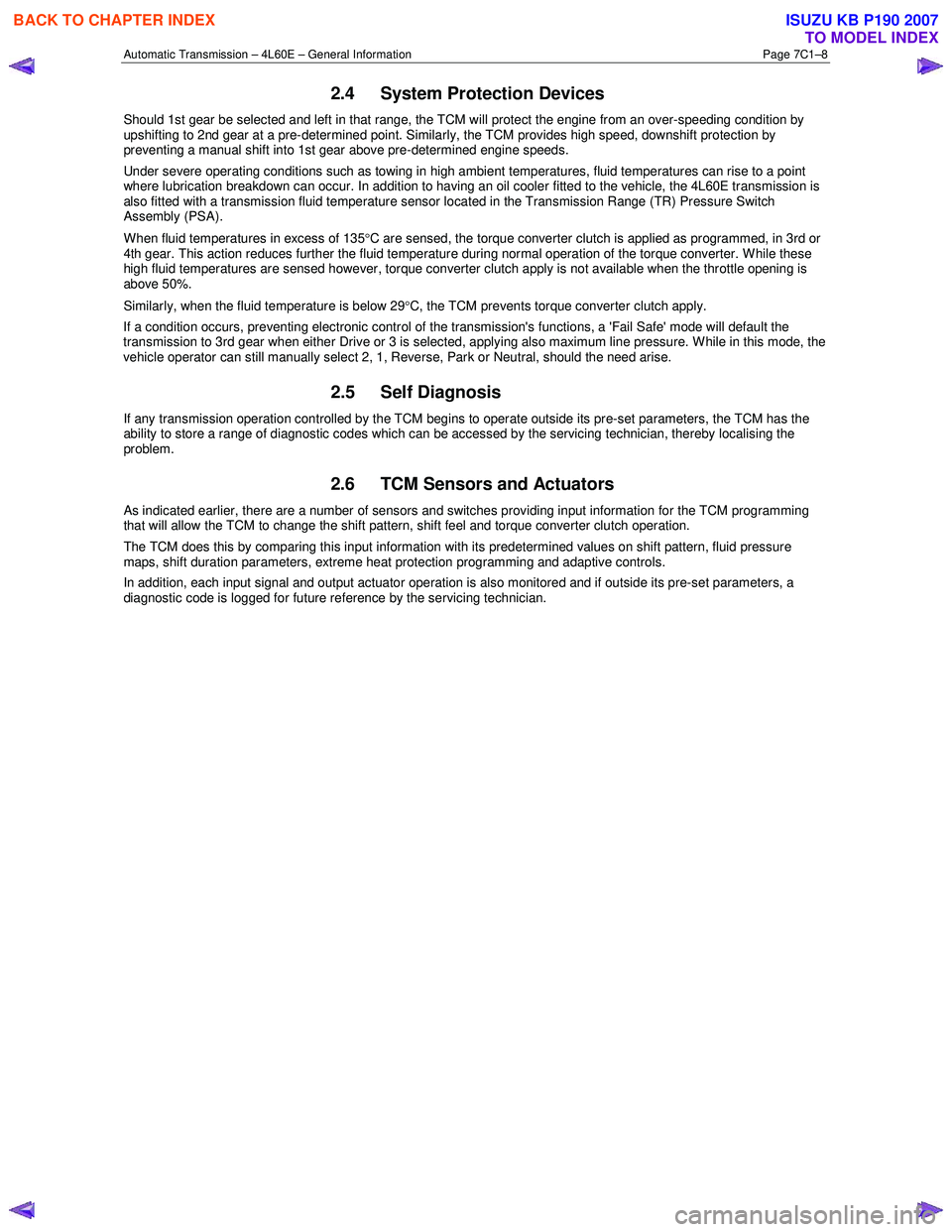
2.4 System Protection Devices
Should 1st gear be selected and left in that range, the TCM will protect the engine from an over-speeding condition by
upshifting to 2nd gear at a pre-determined point. Similarly, the TCM provides high speed, downshift protection by
preventing a manual shift into 1st gear above pre-determined engine speeds.
Under severe operating conditions such as towing in high ambient temperatures, fluid temperatures can rise to a point
where lubrication breakdown can occur. In addition to having an oil cooler fitted to the vehicle, the 4L60E transmission is
also fitted with a transmission fluid temperature sensor located in the Transmission Range (TR) Pressure Switch
Assembly (PSA).
When fluid temperatures in excess of 135 °C are sensed, the torque converter clutch is applied as programmed, in 3rd or
4th gear. This action reduces further the fluid temperature during normal operation of the torque converter. While these
high fluid temperatures are sensed however, torque converter clutch apply is not available when the throttle opening is
above 50%.
Similarly, when the fluid temperature is below 29 °C, the TCM prevents torque converter clutch apply.
If a condition occurs, preventing electronic control of the transmission's functions, a 'Fail Safe' mode will default the
transmission to 3rd gear when either Drive or 3 is selected, applying also maximum line pressure. W hile in this mode, the
vehicle operator can still manually select 2, 1, Reverse, Park or Neutral, should the need arise.
2.5 Self Diagnosis
If any transmission operation controlled by the TCM begins to operate outside its pre-set parameters, the TCM has the
ability to store a range of diagnostic codes which can be accessed by the servicing technician, thereby localising the
problem.
2.6 TCM Sensors and Actuators
As indicated earlier, there are a number of sensors and switches providing input information for the TCM programming
that will allow the TCM to change the shift pattern, shift feel and torque converter clutch operation.
The TCM does this by comparing this input information with its predetermined values on shift pattern, fluid pressure
maps, shift duration parameters, extreme heat protection programming and adaptive controls.
In addition, each input signal and output actuator operation is also monitored and if outside its pre-set parameters, a
diagnostic code is logged for future reference by the servicing technician.
BACK TO CHAPTER INDEX
TO MODEL INDEX
ISUZU KB P190 2007
Page 3772 of 6020
Automatic Transmission – 4L60E – General Information Page 7C1–12
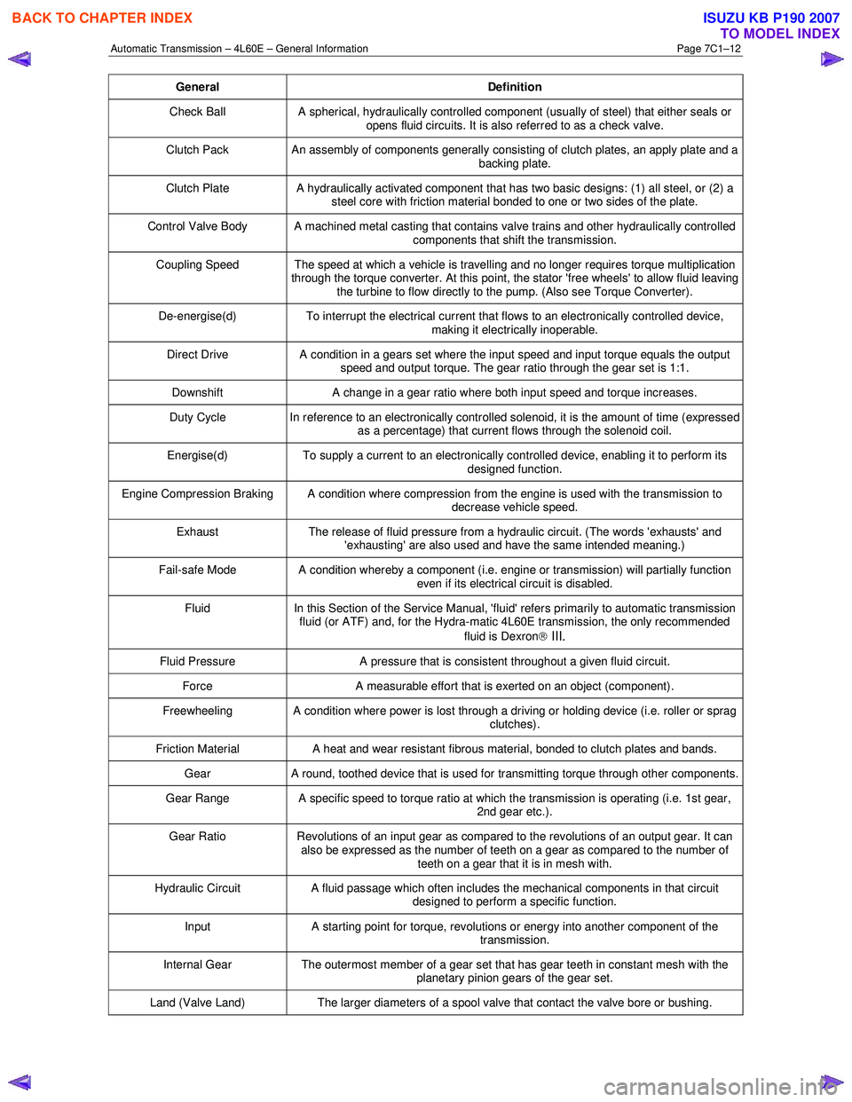
General Definition
Check Ball A spherical, hydraulically controlled component (usually of steel) that either seals or
opens fluid circuits. It is also referred to as a check valve.
Clutch Pack An assembly of components generally consisting of clutch plates, an apply plate and a
backing plate.
Clutch Plate A hydraulically activated component that has two basic designs: (1) all steel, or (2) a
steel core with friction material bonded to one or two sides of the plate.
Control Valve Body A machined metal casting that contains valve trains and other hydraulically controlled components that shift the transmission.
Coupling Speed The speed at which a vehicle is travelling and no longer requires torque multiplication through the torque converter. At this point, the stator 'free wheels' to allow fluid leaving
the turbine to flow directly to the pump. (Also see Torque Converter).
De-energise(d) To interrupt the electrical current that flows to an electronically controlled device,
making it electrically inoperable.
Direct Drive A condition in a gears set where the input speed and input torque equals the output
speed and output torque. The gear ratio through the gear set is 1:1.
Downshift A change in a gear ratio where both input speed and torque increases.
Duty Cycle In reference to an electronically controlled solenoid, it is the amount of time (expressed
as a percentage) that current flows through the solenoid coil.
Energise(d) To supply a current to an electronically controlled device, enabling it to perform its
designed function.
Engine Compression Braking A condition where compression from the engine is used with the transmission to decrease vehicle speed.
Exhaust The release of fluid pressure from a hydraulic circuit. (The words 'exhausts' and
'exhausting' are also used and have the same intended meaning.)
Fail-safe Mode A condition whereby a component (i.e. engine or transmission) will partially function even if its electrical circuit is disabled.
Fluid In this Section of the Service Manual, 'fluid' refers primarily to automatic transmission
fluid (or ATF) and, for the Hydra-matic 4L60E transmission, the only recommended
fluid is Dexron
III.
Fluid Pressure A pressure that is consistent throughout a given fluid circuit.
Force A measurable effort that is exerted on an object (component).
Freewheeling A condition where power is lost through a driving or holding device (i.e. roller or sprag
clutches).
Friction Material A heat and wear resistant fibrous material, bonded to clutch plates and bands.
Gear A round, toothed device that is used for transmitting torque through other components.
Gear Range A specific speed to torque ratio at which the transmission is operating (i.e. 1st gear,
2nd gear etc.).
Gear Ratio Revolutions of an input gear as compared to the revolutions of an output gear. It can
also be expressed as the number of teeth on a gear as compared to the number of
teeth on a gear that it is in mesh with.
Hydraulic Circuit A fluid passage which often includes the mechanical components in that circuit
designed to perform a specific function.
Input A starting point for torque, revolutions or energy into another component of the
transmission.
Internal Gear The outermost member of a gear set that has gear teeth in constant mesh with the
planetary pinion gears of the gear set.
Land (Valve Land) The larger diameters of a spool valve that contact the valve bore or bushing.
BACK TO CHAPTER INDEX
TO MODEL INDEX
ISUZU KB P190 2007
Page 3914 of 6020
Automatic Transmission – 4L60E – On-vehicle Servicing Page 7C4–1
7C4
Automatic Transmission – 4L60E –
On-vehicle Servicing
ATTENTION
Before performing any service operation or other procedure described in this Section, refer to General Information Warnings, Cautions and Notes for correct workshop practices with regard to safety and/or property damage.
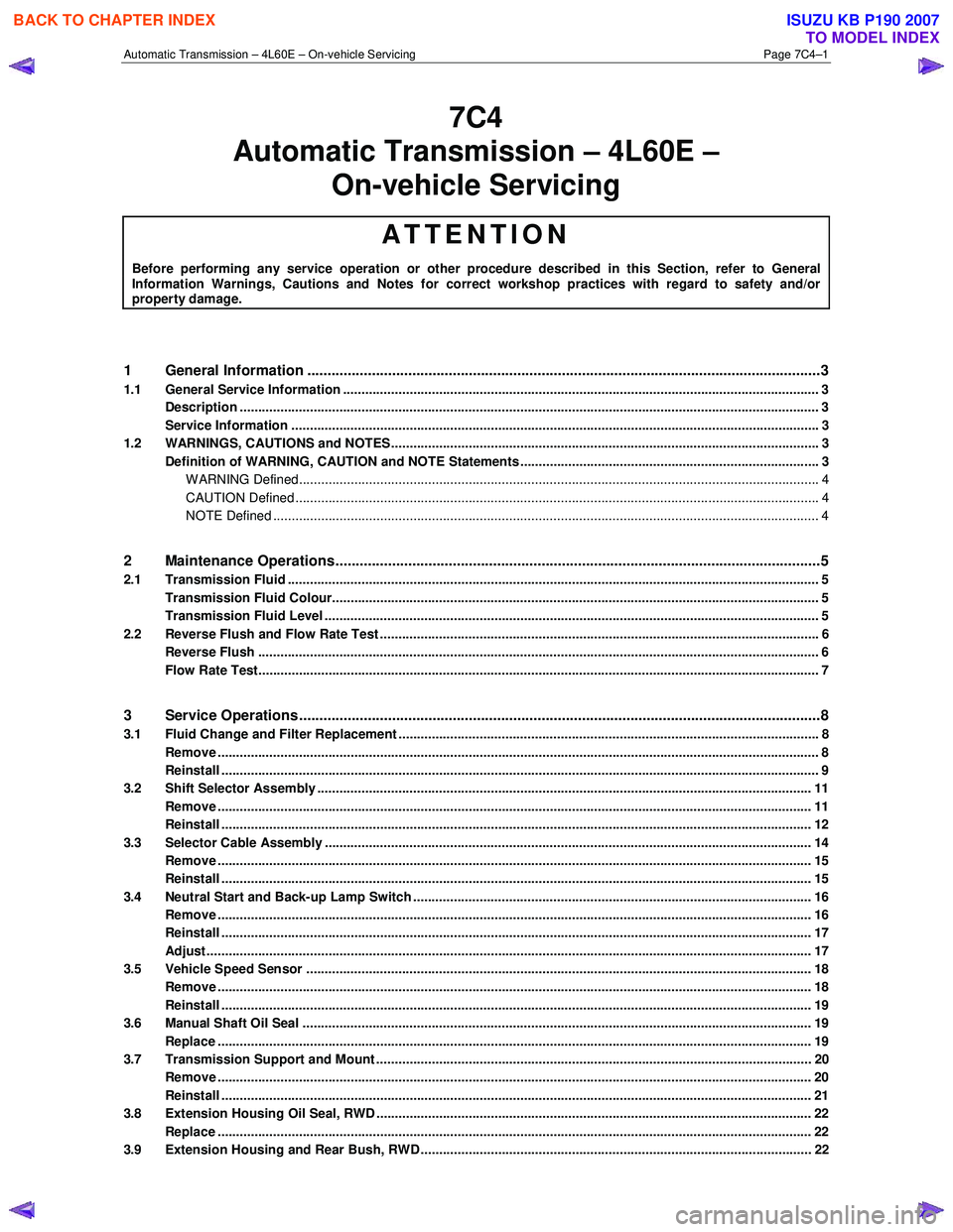
1 General Information ............................................................................................................ ...................3
1.1 General Service Information ................................................................................................................................. 3
Description ............................................................................................................................................................. 3
Service Information ............................................................................................................ ................................... 3
1.2 WARNINGS, CAUTIONS and NOTES................................................................................................... ................. 3
Definition of WARNING, CAUTION and NOTE Statements ............................................................................. .... 3
WARNING Defined............................................................................................................................................. 4
CAUTION Defined .............................................................................................................................................. 4
NOTE Defined .................................................................................................................................................... 4
2 Maintenance Operations......................................................................................................... ...............5
2.1 Transmission Fluid ................................................................................................................................................ 5
Transmission Fluid Colour...................................................................................................... .............................. 5
Transmission Fluid Level ...................................................................................................................................... 5
2.2 Reverse Flush and Flow Rate Test ............................................................................................... ........................ 6
Reverse Flush ........................................................................................................................................................ 6
Flow Rate Test........................................................................................................................................................ 7
3 Service Operations ............................................................................................................. ....................8
3.1 Fluid Change and Filter Replacement ............................................................................................ ...................... 8
Remove ................................................................................................................................................................... 8
Reinstall .................................................................................................................................................................. 9
3.2 Shift Selector Assembly ...................................................................................................................................... 11
Remove ................................................................................................................................................................. 11
Reinstall ................................................................................................................................................................ 12
3.3 Selector Cable Assembly .................................................................................................................................... 14
Remove ................................................................................................................................................................. 15
Reinstall ................................................................................................................................................................ 15
3.4 Neutral Start and Back-up Lamp Switch ............................................................................................................ 16
Remove ................................................................................................................................................................. 16
Reinstall ................................................................................................................................................................ 17
Adjust .................................................................................................................................................................... 17
3.5 Vehicle Speed Sensor ......................................................................................................................................... 18
Remove ................................................................................................................................................................. 18
Reinstall ................................................................................................................................................................ 19
3.6 Manual Shaft Oil Seal .......................................................................................................................................... 19
Replace ................................................................................................................................................................. 19
3.7 Transmission Support and Mount ................................................................................................. ..................... 20
Remove ................................................................................................................................................................. 20
Reinstall ................................................................................................................................................................ 21
3.8 Extension Housing Oil Seal, RWD ...................................................................................................................... 22
Replace ................................................................................................................................................................. 22
3.9 Extension Housing and Rear Bush, RWD ........................................................................................... ............... 22
BACK TO CHAPTER INDEX
TO MODEL INDEX
ISUZU KB P190 2007
Page 3921 of 6020
Automatic Transmission – 4L60E – On-vehicle Servicing Page 7C4–8
3 Service Operations
3.1 Fluid Change and Filter Replacement
To avoid personal injury take note of the
following:
• Avoid accidental hot oil spillage by
performing fluid change only when the
transmission fluid is cold.
• Wear safety glasses and gloves when
using compressed air and cleaning fluids.
Remove
1 Raise the vehicle and support in a safe manner, refer to 0A General Information.
2 Clean all dirt from around the oil pan and the transmission case.
3 Place a suitable sized drain tray under the transmission.
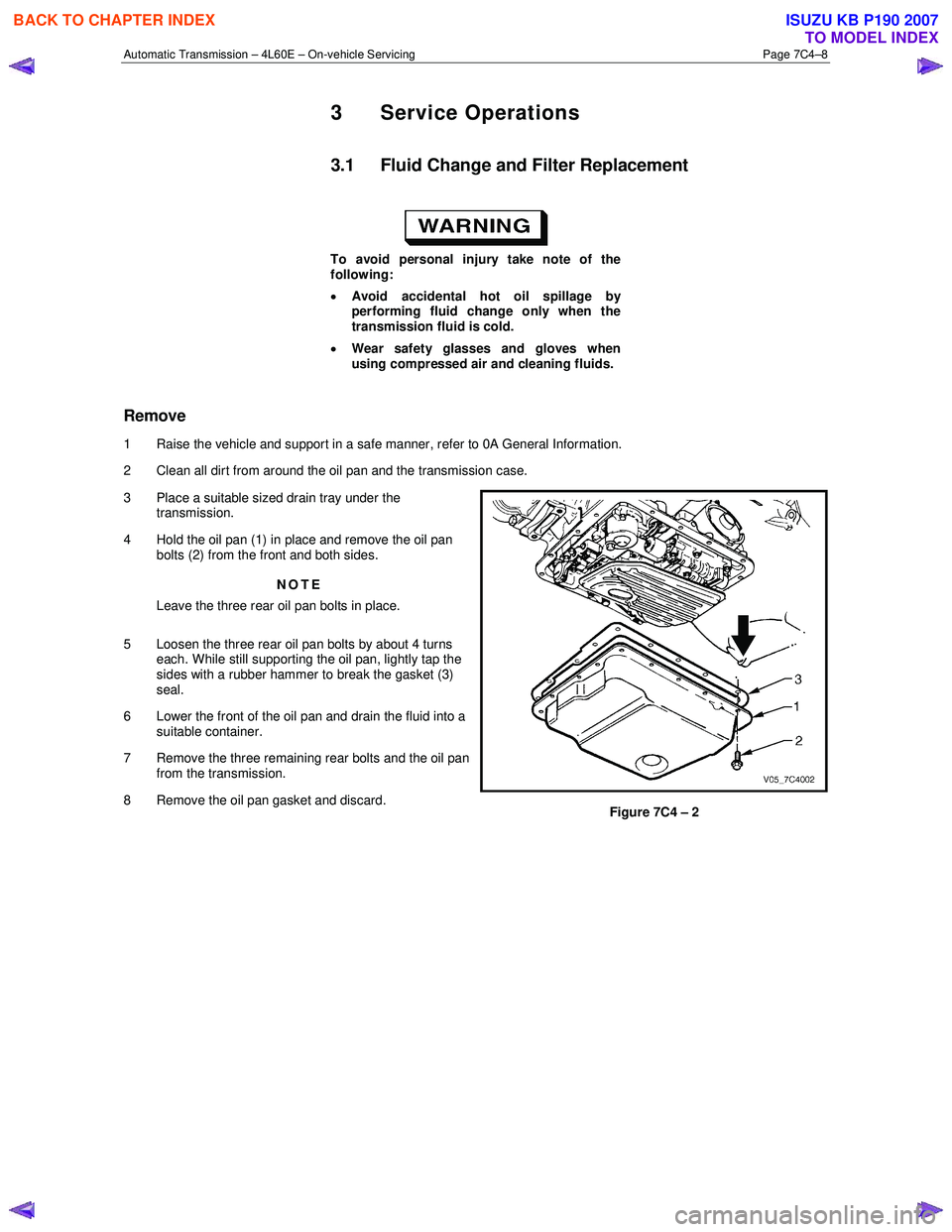
4 Hold the oil pan (1) in place and remove the oil pan bolts (2) from the front and both sides.
NOTE
Leave the three rear oil pan bolts in place.
5 Loosen the three rear oil pan bolts by about 4 turns each. While still supporting the oil pan, lightly tap the
sides with a rubber hammer to break the gasket (3)
seal.
6 Lower the front of the oil pan and drain the fluid into a suitable container.
7 Remove the three remaining rear bolts and the oil pan from the transmission.
8 Remove the oil pan gasket and discard.
Figure 7C4 – 2
BACK TO CHAPTER INDEX
TO MODEL INDEX
ISUZU KB P190 2007
Page 3938 of 6020
Automatic Transmission – 4L60E – On-vehicle Servicing Page 7C4–25
3.11 Shift Solenoid Locations
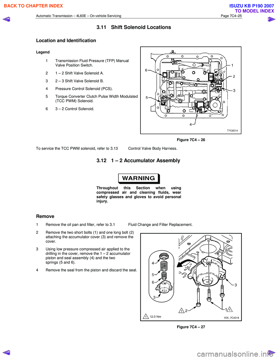
Location and Identification
Legend
1 Transmission Fluid Pressure (TFP) Manual Valve Position Switch.
2 1 – 2 Shift Valve Solenoid A.
3 2 – 3 Shift Valve Solenoid B.
4 Pressure Control Solenoid (PCS).
5 Torque Converter Clutch Pulse W idth Modulated (TCC PWM) Solenoid.
6 3 – 2 Control Solenoid.
Figure 7C4 – 26
To service the TCC PWM solenoid, refer to 3.13 Control Valve Body Harness.
3.12 1 – 2 Accumulator Assembly
Throughout this Section when using
compressed air and cleaning fluids, wear
safety glasses and gloves to avoid personal
injury.
Remove
1 Remove the oil pan and filter, refer to 3.1 Fluid Change and Filter Replacement.
2 Remove the two short bolts (1) and one long bolt (2) attaching the accumulator cover (3) and remove the
cover.
3 Using low pressure compressed air applied to the drilling in the cover, remove the 1 – 2 accumulator
piston and seal assembly (4) and the two
springs (5 and 6).
4 Remove the seal from the piston and discard the seal.
Figure 7C4 – 27
BACK TO CHAPTER INDEX
TO MODEL INDEX
ISUZU KB P190 2007