2007 ISUZU KB P190 transfer control system
[x] Cancel search: transfer control systemPage 21 of 6020

MAINTENANCE AND LUBRICATION 0B-3
I : Inspect and correct or replace as necessary A : Adjust
R : Replace or change T : Tighten to specified torque L : Lubricate
SERVICE INTERVAL: × 1,000 km 5 10 15 20 25 30 35 40 45 50 55 60 65 70 75 80 85 90 95 100(Use odometer reading × 1,000 miles 3 6 9 12 15 18 21 24 27 30 33 36 39 42 45 48 51 54 57 60or months whichever
comes first)
or months 6 12 18 24 30 36 42 48 54 60 66 72 78 84 90 96 102 108 114 120
CLUTCH
Clutch fluid I I - I - I - I - I - I - I - I - I - I Clutch pedal travel and free play I I - I - I - I - I - I - I - I - I - I TRANSMISSION OR TRANSMISSION
W ITH TRANSFER CASE
* Automatic transmission fluid (HFV6)
- - I - - I - - I - - I - - I - - I - R (4JH1-TC, 4JJ1 (Standard Output),
4JJ1 (High Output)) - - - I - - - I - - - I - - - I - - - I
* Transfer case oil
- - - I - - - I - - - I - - - I - - - I * Manual transmission fluid - R - I - - - R - - - I - - - R - - - I Oil leakage I I I I I I I I I I I I I I I I I I I I Gear control mechanism for
looseness - - - I - - - I - - - I - - - I - - - I
PROPELLER SHAFT Loose connections - I - I - I - I - I - I - I - I - I - I * Universal joints and splines for wear
- I - I - I - I - I - I - I - I - I - I Universal joints and sliding sleeve
(4W D) - L - L - L - L - L - L - L - L - L - L
FRONT AND REAR AXLE * Differential gear oil (Front and rear) - R - I - - - R - - - I - - - R - - - I Oil leakage I I I I I I I I I I I I I I I I I I I I Shift on the fly system gear oil I - - I - - - I - - - I - - - I - - - I Front axle shaft boot for damage - - - I - - - I - - - I - - - I - - - I Axle shafts for distortion or damage - - - I - - - I - - - I - - - I - - - I Axle case for distortion or damage - - - I - - - I - - - I - - - I - - - I STEERING Power steering fluid I I I I I I I R I I I I I I I R I I I I Oil leakage I I I I I I I I I I I I I I I I I I I I * Steering system for looseness or
damage - I - I - I - I - I - I - I - I - I - I
Power steering hose
- I - I - I - I - I - I - I - R - I - I Steering wheel play I I I I I I I I I I I I I I I I I I I I Steering function I I I I I I I I I I I I I I I I I I I I Right and left turning radius - - - I - - - I - - - I - - - I - - - I W heel alignment - - - I - - - I - - - I - - - I - - - I Joint ball for oil leakage or damage - I - I - I - I - I - I - I - I - I - I Joint ball rubber boot for damage - I - I - I - I - I - I - I - I - I - I SERVICE BRAKES Brake fluid - - - I - - - I - - - I - - - I - - - I Brake system for fluid leakage I I I I I I I I I I I I I I I I I I I I Brake function I I I I I I I I I I I I I I I I I I I I * Rear brake lining and drum wear - I - I - I - I - I - I - I - I - I - I * Front disc brake pads and discs wear - I - I - I - I - I - I - I - I - I - I Brake pedal travel and free play I I I I I I I I I I I I I I I I I I I I Pipes and hoses loose connections
or damage I I - I - I - I - I - I - I - I - I - I
BACK TO CHAPTER INDEX
TO MODEL INDEX
ISUZU KB P190 2007
Page 23 of 6020

MAINTENANCE AND LUBRICATION 0B-5
MAINTENANCE SCHEDULE (For EUROPE)
Items followed by an asterisk (*) require more frequent maintenance if the vehicle is driven under severe conditions.
Replace the fuel filter (**Mark) when the fuel filter indicator light is lit.
Refer to "SEVERE CONDITIONS MAINTENANCE SCHEDULE."
Diesel Engine model (ACEA B2 specification engine oil)
I : Inspect and correct or replace as necessary A : Adjust
R : Replace or change T : Tighten to specified torque L : Lubricate
SERVICE INTERVAL: × 1,000 km 5 10 15 20 25 30 35 40 45 50 55 60 65 70 75 80 85 90 95 100
(Use odometer reading or × 1,000 miles 3 6 9 12 15 18 21 24 27 30 33 36 39 42 45 48 51 54 57 60
months whichever comes
first)
or months 6 12 18 24 30 36 42 48 54 60 66 72 78 84 90 96 102 108 114 120
DIESEL ENGINE * Engine oil - R - R - R - R - R - R - R - R - R - R* Engine oil filter - - - R - - - R - - - R - - - R - - - ROil leakage and contamination I I I I I I I I I I I I I I I I I I I I Idling speed and acceleration I I I I I I I I I I I I I I I I I I I I Fan belt tension and damage I I I I I I I I I I I I I I I I I I I I Exhaust system I I - I - I - I - I - I - I - I - I - I All hoses and pipes in engine
compartment for clog of damage - I I I I I I I I I I I I I I I I I I I
Valve clearance
- - - A - - - A - - - A - - - A - - - A * Air cleaner element I I I I I I I R I I I I I I I R I I I I ** Fuel filter Replace the fuel filter when the fuel filter indicator light is lit. Engine coolant concentration - I - I - I - I - I - I - I - I - I - I Cooling system for water leakage - I - I - I - I - I - I - I - I - I - I CLUTCH Clutch fluid I I - I - I - I - I - I - I - I - I - I Clutch pedal travel and play I I - I - I - I - I - I - I - I - I - I TRANSMISSION OR TRANSMISSION
W ITH TRANSFER CASE
* Manual transmission with fluid - R - I - - - R - - - I - - - R - - - I * Transfer case oil (MT) - - - I - - - I - - - I - - - I - - - I Oil leakage I I I I I I I I I I I I I I I I I I I I Gear control mechanism for
looseness - - - I - - - I - - - I - - - I - - - I
* Automatic transmission fluid - - - I - - - I - - - I - - - I - - - I * Transfer case oil (AT)
- - - I - - - - - - - I - - - - - - - I PROPELLER SHAFT Loose connections - I - I - I - I - I - I - I - I - I - I * Universal joints and splines for wear - I - I - I - I - I - I - I - I - I - I Universal joints and sliding sleeve (4W D) - L - L - L - L - L - L - L - L - L - L
FRONT AND REAR AXLE * Differential gear oil (Front and rear) - R - I - - - R - - - I - - - R - - - I Oil leakage I I I I I I I I I I I I I I I I I I I I Shift on the fly system gear oil I - - I - - - I - - - I - - - I - - - I
Front axle shaft boot for damage - - - I - - - I - - - I - - - I - - - I Axle case for distortion or damage - - - I - - - I - - - I - - - I - - - I Axle shafts for distortion or damage - - - I - - - I - - - I - - - I - - - I
BACK TO CHAPTER INDEX
TO MODEL INDEX
ISUZU KB P190 2007
Page 25 of 6020
MAINTENANCE AND LUBRICATION 0B-7
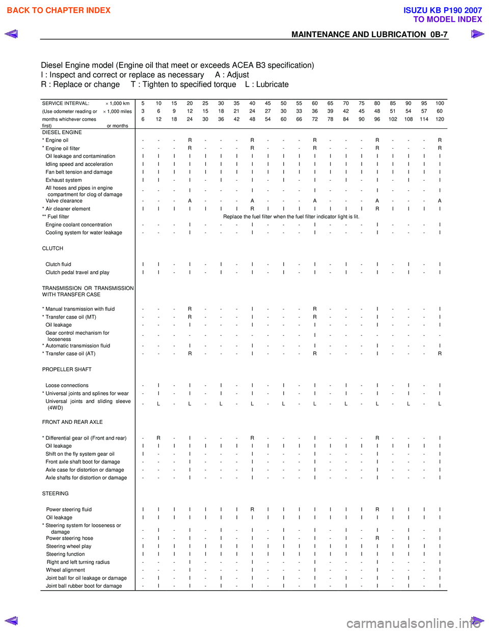
Diesel Engine model (Engine oil that meet or exceeds ACEA B3 specification)
I : Inspect and correct or replace as necessary A : Adjust
R : Replace or change T : Tighten to specified torque L : Lubricate
SERVICE INTERVAL: × 1,000 km 5 10 15 20 25 30 35 40 45 50 55 60 65 70 75 80 85 90 95 100
(Use odometer reading or × 1,000 miles 3 6 9 12 15 18 21 24 27 30 33 36 39 42 45 48 51 54 57 60
months whichever comes
first)
or months 6 12 18 24 30 36 42 48 54 60 66 72 78 84 90 96 102 108 114 120
DIESEL ENGINE * Engine oil - - - R - - - R - - - R - - - R - - - R*
Engine oil filter
- - - R - - - R - - - R - - - R - - - R
Oil leakage and contamination I I I I I I I I I I I I I I I I I I I I Idling speed and acceleration I I I I I I I I I I I I I I I I I I I I Fan belt tension and damage I I I I I I I I I I I I I I I I I I I I Exhaust system I I - I - I - I - I - I - I - I - I - I All hoses and pipes in engine
compartment for clog of damage - - - I - - - I - - - I - - - I - - - I
Valve clearance
- - - A - - - A - - - A - - - A - - - A * Air cleaner element I I I I I I I R I I I I I I I R I I I I ** Fuel filter Replace the fuel filter when the fuel filter indicator light is lit. Engine coolant concentration - - - I - - - I - - - I - - - I - - - I Cooling system for water leakage - - - I - - - I - - - I - - - I - - - I CLUTCH Clutch fluid I I - I - I - I - I - I - I - I - I - I Clutch pedal travel and play I I - I - I - I - I - I - I - I - I - I TRANSMISSION OR TRANSMISSION
W ITH TRANSFER CASE
* Manual transmission with fluid - - - R - - - I - - - R - - - I - - - I * Transfer case oil (MT) - - - R - - - I - - - R - - - I - - - I Oil leakage - - - I - - - I - - - I - - - I - - - I Gear control mechanism for
looseness - - - - - - - - - - - I - - - - - - - -
* Automatic transmission fluid - - - I - - - I - - - I - - - I - - - I * Transfer case oil (AT)
- - - R - - - I - - - R - - - I - - - R PROPELLER SHAFT Loose connections - I - I - I - I - I - I - I - I - I - I * Universal joints and splines for wear - I - I - I - I - I - I - I - I - I - I Universal joints and sliding sleeve
(4W D) - L - L - L - L - L - L - L - L - L - L
FRONT AND REAR AXLE
* Differential gear oil (Front and rear) - R - I - - - R - - - I - - - R - - - I Oil leakage I I I I I I I I I I I I I I I I I I I I Shift on the fly system gear oil I - - I - - - I - - - I - - - I - - - I Front axle shaft boot for damage - - - I - - - I - - - I - - - I - - - I Axle case for distortion or damage - - - I - - - I - - - I - - - I - - - I Axle shafts for distortion or damage - - - I - - - I - - - I - - - I - - - I STEERING Power steering fluid I I I I I I I R I I I I I I I R I I I I Oil leakage I I I I I I I I I I I I I I I I I I I I * Steering system for looseness or
damage - I - I - I - I - I - I - I - I - I - I
Power steering hose
- I - I - I - I - I - I - I - R - I - I Steering wheel play I I I I I I I I I I I I I I I I I I I I Steering function I I I I I I I I I I I I I I I I I I I I Right and left turning radius - - - I - - - I - - - I - - - I - - - I W heel alignment - - - I - - - I - - - I - - - I - - - I Joint ball for oil leakage or damage - I - I - I - I - I - I - I - I - I - I Joint ball rubber boot for damage - I - I - I - I - I - I - I - I - I - I
BACK TO CHAPTER INDEX
TO MODEL INDEX
ISUZU KB P190 2007
Page 580 of 6020

4C2-2 SHIFT ON THE FLY SYSTEM
SHIFT ON THE FLY SYSTEM
Outline of Shift on The Fly System
The shift on the fly system switches between 2 wheel
drive (2W D) and 4 wheel drive (4W D) electrically b
y
driver's pressing the 4W D switch (push button type) on
instrument panel.
This system controls below operations.
1. Shifting the transfer front output gear (Connecting to,
and disconnecting from, front propeller shaft b
y
motor actuator).
2. Retrial of shifting the transfer front output gear.
3. Connecting front wheels to, and disconnecting them from, the front axles by axle motor actuator.
4. Indicator on instrument panel.
5. 4W D out signal to other Electronic Hydraulic Control Unit.
System Diagrams
RUW 34BLF000201
BACK TO CHAPTER INDEX
TO MODEL INDEX
ISUZU KB P190 2007
Page 607 of 6020

5A-14 BRAKE CONTROL SYSTEM
Connector List
No. Connector face No. Connector face
B-23
White
Meter-A C-36
SilverEngine room - LH ; Ground
B-24
White
Meter-B C-44
WhiteStoplight switch
B-48
Black
G sensor C-53
OrangeABS sensor Front-RH
B-54
White
J/B I2 C-54
OrangeABS sensor Front-LH
B-56
White
J/B I4 C-67
Black
EHCU
B-58
Black
Data link connector C-107
WhiteJ/B E2
B-62
White
Ignition switch (IGSUB : G1) C-108
WhiteJ/B E1
B-63
White
Ignition switch (IGSUB : G2) C-109
SilverBody-LH ; ground
B-82
Silver
W eld splice 6 (Ground) C-111
BlackTransfer case control module
C-2
Silver
Engine room - RH ground F-4
Gray ABS sensor
BACK TO CHAPTER INDEX
TO MODEL INDEX
ISUZU KB P190 2007
Page 614 of 6020

BRAKE CONTROL SYSTEM 5A-21
EHCU Side
Pin No. Pin Function
Wire Color Typical Value Note
20 Stop Light Switch RED Open: 0V
Close: Battery Voltage Close Condition:
Step on the Brake
Pedal
21 G Sensor Signal YEL/BLK 2.0~3.0V
(MAX 4.0V, MIN 1.0V) 4W D Only
It checks in a flat place
(0G: 2.5V)
DTC C0276, C0285
22 ABS W arning Lamp YEL More than 10V -
23 Not Used - - -
24 Transfer (2-4W D Control Unit) GRY Pulse Signal
(High 4.5V, Low 1.5V) 4W D Only
DTC C0282
25 Serial ORN/W HT- Short to GND:
Flash out DTCs
26 Not Used - - -
BACK TO CHAPTER INDEX
TO MODEL INDEX
ISUZU KB P190 2007
Page 676 of 6020
BRAKE CONTROL SYSTEM 5A-83
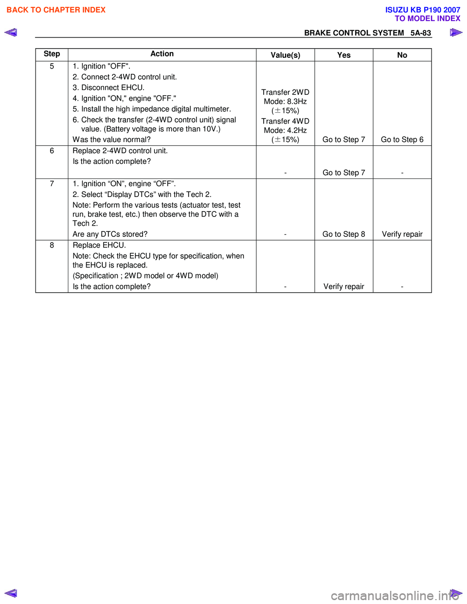
Step Action
Value(s) Yes No
5 1. Ignition "OFF".
2. Connect 2-4W D control unit.
3. Disconnect EHCU.
4. Ignition "ON," engine "OFF."
5. Install the high impedance digital multimeter.
6. Check the transfer (2-4W D control unit) signal value. (Battery voltage is more than 10V.)
W as the value normal? Transfer 2W D
Mode: 8.3Hz (± 15%)
Transfer 4W D Mode: 4.2Hz (± 15%) Go to Step 7 Go to Step 6
6 Replace 2-4W D control unit.
Is the action complete?
- Go to Step 7 -
7 1. Ignition “ON”, engine “OFF”. 2. Select “Display DTCs” with the Tech 2. Note: Perform the various tests (actuator test, test
run, brake test, etc.) then observe the DTC with a
Tech 2.
Are any DTCs stored? - Go to Step 8 Verify repair
8 Replace EHCU.
Note: Check the EHCU type for specification, when
the EHCU is replaced.
(Specification ; 2W D model or 4W D model)
Is the action complete? - Verify repair -
BACK TO CHAPTER INDEX
TO MODEL INDEX
ISUZU KB P190 2007
Page 970 of 6020

6C – 6 FUEL SYSTEM
INJECTION PUMP
RTW 46CLF000201
4JA1T(L):
A Bosch Distributor Type Injection Pump is used. A single reciprocating/revolving plunger delivers the fuel uniformly
to the injection nozzles, regardless of the number of cylinders.
The governor, the injection timer, and the feed pump are all contained in the injection pump housing. The injection
pump is compact, light weight, and provides reliable high-speed operation.
The vacuum-type fast idle actuator increases the engine idling speed to provide the additional power required to
operate the air conditioner.
Fast idler diaphragm movement is caused by changes in the negative pressure created by the engine’s vacuum
pump.
The diaphragm motion is transferred to the injection pump control lever to increase or decrease the idling speed.
4JA1TC/4JH1TC:
The Bosch VP44 injection pump is electronically controlled. The pump controller combine to injection pump.
Signals from the pump controller are sent to the engine control module (ECM). In response to these signals, the
ECM selects the optimum fuel injection timing and volume for the existing driving conditions.
BACK TO CHAPTER INDEX
TO MODEL INDEX
ISUZU KB P190 2007