2007 ISUZU KB P190 transfer control system
[x] Cancel search: transfer control systemPage 3147 of 6020
Engine Cooling – V6 Engine Page 6B1–12
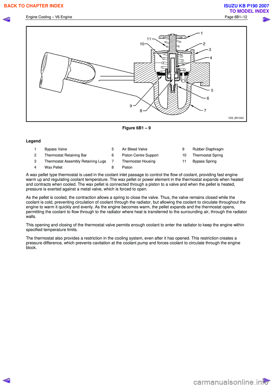
Figure 6B1 – 9
Legend
1 Bypass Valve
2 Thermostat Retaining Bar
3 Thermostat Assembly Retaining Lugs
4 Wax Pellet 5 Air Bleed Valve
6 Piston Centre Support
7 Thermostat Housing
8 Piston 9 Rubber Diaphragm
10 Thermostat Spring
11 Bypass Spring
A wax pellet type thermostat is used in the coolant inlet passage to control the flow of coolant, providing fast engine
warm up and regulating coolant temperature. The wax pellet or power element in the thermostat expands when heated
and contracts when cooled. The wax pellet is connected through a piston to a valve and when the pellet is heated,
pressure is exerted against a metal valve, which is forced to open.
As the pellet is cooled, the contraction allows a spring to close the valve. Thus, the valve remains closed while the
coolant is cold, preventing circulation of coolant through the radiator, but allowing the coolant to circulate throughout the
engine to warm it quickly and evenly. As the engine becomes warm, the pellet expands and the thermostat opens,
permitting the coolant to flow through to the radiator where heat is transferred to the surrounding air, through the radiator
walls.
This opening and closing of the thermostat valve permits enough coolant to enter the radiator to keep the engine within
specified temperature limits.
The thermostat also provides a restriction in the cooling system, even after it has opened. This restriction creates a
pressure difference, which prevents cavitation at the coolant pump and forces coolant to circulate through the engine
block.
BACK TO CHAPTER INDEX
TO MODEL INDEX
ISUZU KB P190 2007
Page 3259 of 6020
Engine Management – V6 – General Information Page 6C1-1–17
3.9 Serial Data Communication System
The engine control module (ECM) communicates directly with the following control units using the General Motors local
area network (GM LAN) serial data communication protocol:
• Transmission control module (TCM) (if fitted)
• Powertrain interface module (PIM)
The immobiliser control unit (ICU) communicates directly with the PIM using Keyword 2000 serial data communication
protocol. Refer to 11A Immobiliser for further information
As the GM LAN serial data communication protocol is not compatible with the Keyword 2000 serial data communication
protocol, a powertrain interface module (PIM) is integrated to the serial data communication system to perform the
following tasks (Refer to 6E1 Powertrain Interface Module – V6):
• Translate the GM LAN serial data transmitted by the ECM into a Keyword 2000 serial data that can be received
and recognised by the ICU.
• Translate the cruise control switch, automatic transmission power mode switch and 3
rd start switch signal into a GM
LAN serial data that can be received and recognised by the ECM.
3.10 Self Diagnostics System
The ECM constantly performs self-diagnostic tests on the engine management system. W hen the ECM detects a
malfunction, it also stores a diagnostic trouble code (DTC). A stored DTC will identify the problem area(s) and is
designed to assist the technician in rectifying the fault. In addition, DTCs are classified as either Current or History DTC.
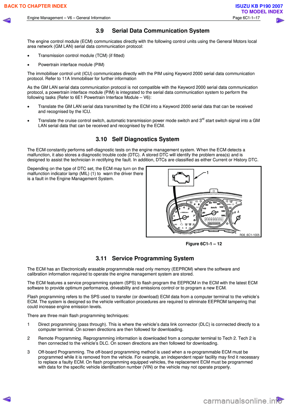
Depending on the type of DTC set, the ECM may turn on the
malfunction indicator lamp (MIL) (1) to warn the driver there
is a fault in the Engine Management System.
Figure 6C1-1 – 12
3.11 Service Programming System
The ECM has an Electronically erasable programmable read only memory (EEPROM) where the software and
calibration information required to operate the engine management system are stored.
The ECM features a service programming system (SPS) to flash program the EEPROM in the ECM with the latest ECM
software to provide optimum performance, driveability and emissions control or to program a new ECM.
Flash programming refers to the SPS used to transfer (or download) ECM data from a computer terminal to the vehicle’s
ECM. The system is designed so the vehicle verification procedures are required to eliminate EEPROM tampering that
could increase engine emission levels.
There are three main flash programming techniques:
1 Direct programming (pass through). This is where the vehicle’s data link connector (DLC) is connected directly to a computer terminal. On screen directions are then followed for downloading.
2 Remote Programming. Reprogramming information is downloaded from a computer terminal to Tech 2. Tech 2 is then connected to the vehicle’s DLC. On screen directions are then followed for downloading.
3 Off-board Programming. The off-board programming method is used when a re-programmable ECM must be programmed while it is removed from the vehicle. For example, an independent repair facility may find it necessary
to replace a faulty ECM. On flash programming equipped vehicles, the replacement ECM must be programmed
with data for the specific vehicle identification number (VIN) or the vehicle may not operate properly.
BACK TO CHAPTER INDEX
TO MODEL INDEX
ISUZU KB P190 2007
Page 3397 of 6020
Engine Management – V6 – Diagnostics Page 6C1-2–119
The ECM applies control voltage to the control circuit of the ignition coil during the calculated dwell period that allows
current flow to the ignition coil primary winding to generate a magnetic flux field. At the appropriate firing point, the ECM
interrupts the control voltage applied to the ignition coil.
Interruption of voltage applied to the control circuit of the ignition coil primary winding induces the transfer of electrical
energy from the ignition coil primary winding to the ignition coil secondary winding, which triggers the ignition coil to
produce a spark at the spark plug.
An ignition coil control circuit DTC sets if the ECM detects a fault condition in the control circuit of an ignition coil.
Conditions for Running the DTC
Run continuously once the following conditions are met:
• The engine is running.
• The engine speed is 480 – 5,000 rpm
• The battery voltage is 10.0 – 16.0 V.
Conditions for Setting the DTC
DTC P0351, P0352, P0353, P0354, P0355 or P0356
The ECM detects an open circuit fault condition in the ignition coil control circuit.
DTC P2300, P2303, P2306, P2309, P2312 or P2315
The ECM detects a short to ground fault condition in the ignition coil control circuit.
DTC P2301, P2304, P2307, P2310, P2313 and P2316
The ECM detects a short to voltage fault condition in the ignition coil control circuit.
Conditions for Clearing the DTC
The ignition coil control circuit DTCs are Type B DTCs. Refer to 1.4 Diagnostic Trouble Codes in this Section, for
action taken when Type B DTC sets and conditions for clearing Type B DTCs.
Additional Information
• Refer to 6C1-1 Engine Management – V6 – General Information for details of the ignition coil operation.
• A short to voltage fault condition damages the ignition coil. Do not replace the ignition until this fault condition is
rectified.
• The ignition coils for each bank of the engine are fused separately. If all DTCs for a single bank are set, there may
be a fault in one of the ignition supply circuits.
• The ignition coils for each bank of the engine have a separate ground connections. If all DTCs for a single bank
are set, there may be a fault in one of the ground circuits.
• For an intermittent fault condition, refer to 5.2 Intermittent Fault Conditions in this Section.
• Since fault condition in a wiring connector may trigger DTCs, always test the connectors related to this diagnostic
procedure for shorted terminals or poor wiring connection before replacing any component. Refer to 8A Electrical -
Body and Chassis for information on electrical fault diagnosis.
• To assist diagnosis, refer to 3 W iring Diagrams and Connector Charts in this Section, for the system wiring
diagram and connector charts.
Test Description
The following numbers refer to the step numbers in the diagnostic table:
3 Determines if there is a fault condition in the ignition voltage supply circuit.
5 Determines if there is a fault condition in the ground circuits of the ignition coil.
6 Tests if the ECM is commanding the ignition coil on and off.
BACK TO CHAPTER INDEX
TO MODEL INDEX
ISUZU KB P190 2007
Page 3761 of 6020
Automatic Transmission – 4L60E – General Information Page 7C1–1
7C1
Automatic Transmission – 4L60E –
General Information
ATTENTION
Before performing any service operation or other procedure described in this Section, refer to Warnings, Cautions and Notes for correct workshop practices with regard to safety and/or property damage.
1 Section Descriptions ........................................................................................................... ...................3
1.1 WARNINGS, CAUTIONS and NOTES................................................................................................... ................. 3
Definition of WARNING, CAUTION and NOTE Statements ............................................................................. .... 3
WARNING Defined............................................................................................................................................. 3
CAUTION Defined .............................................................................................................................................. 3
NOTE Defined .................................................................................................................................................... 3
1.2 7C1 Automatic Transmission – 4L60E – General Information ....................................................................... .... 4
Recommendations ................................................................................................................................................. 4
Oil Cooler Pipes ..................................................................................................................................................... 4
Clean and Inspect .............................................................................................................. .................................... 5
1.3 7C2 Automatic Transmission – 4L60E – Electrical Diagnosis ...................................................................... ..... 5
1.4 7C3 Automatic Transmission – 4L60E – Hydraulic and Mechanical Diagnosis ............................................... 5
1.5 7C4 Automatic Transmission – 4L60E – On-vehicle Servicing ...................................................................... .... 5
2 General information ...............................................................................................................................6
2.1 Transmission Control Module – HFV6 ............................................................................................. .................... 6
2.2 Transmission Identification .................................................................................................................................. 6
2.3 Economy, Power and Cruise Modes .................................................................................................................... 7
Economy Mode ...................................................................................................................................................... 7
Power Mode ............................................................................................................................................................ 7
Cruise Mode ........................................................................................................................................................... 7
2.4 System Protection Devices ...................................................................................................... ............................. 8
2.5 Self Diagnosis ........................................................................................................................................................ 8
2.6 TCM Sensors and Actuators ................................................................................................................................. 8
3 Transmission Control Module Operation Overview ...........................................................................9
3.1 Transmission Control Module .............................................................................................................................. 9
Component Location ............................................................................................................. ................................ 9
Transmission Control Module Data Transfer ...................................................................................... ................ 9
Transmission Control Module Operation........................................................................................................... 10
3.2 TCM Wiring Diagrams.......................................................................................................................................... 10
4 Transmission Definitions and Abbreviations ....................................................................................1 1
4.1 Throttle Position Related Definitions ................................................................................................................. 11
4.2 Noise Condition Related Definitions ............................................................................................ ...................... 11
4.3 General Definitions .............................................................................................................................................. 11
4.4 Abbreviations ....................................................................................................................................................... 14
5 Service Notes ........................................................................................................................................15
Fasteners .............................................................................................................................................................. 15
General Workshop Practice ................................................................................................................................ 15
6 Torque Specifications .......................................................................................................... ................16
7 Transmission Specifications.................................................................................................... ...........17
BACK TO CHAPTER INDEX
TO MODEL INDEX
ISUZU KB P190 2007
Page 3769 of 6020
Automatic Transmission – 4L60E – General Information Page 7C1–9
3 Transmission Control Module
Operation Overview
3.1 Transmission Control Module
W ith the introduction of the new HFV6 engine, the powertrain architecture has been redesigned to accommodate this
introduction. W ith this design, a new bus architecture and protocol has also been introduced. The new bus connects the
following modules:
• engine control module (ECM),
• transmission control module (TCM),
• powertrain interface module (PIM) and
• ABS module.
The protocol used to communicate between these modules is called General Motors Local Area Network (GM LAN)
which is based on Controller Area Network (CAN) communication protocol. For further information on GM LAN protocol
and data bus structure, refer to 6E1 Powertrain Interface Module – V6.
Component Location
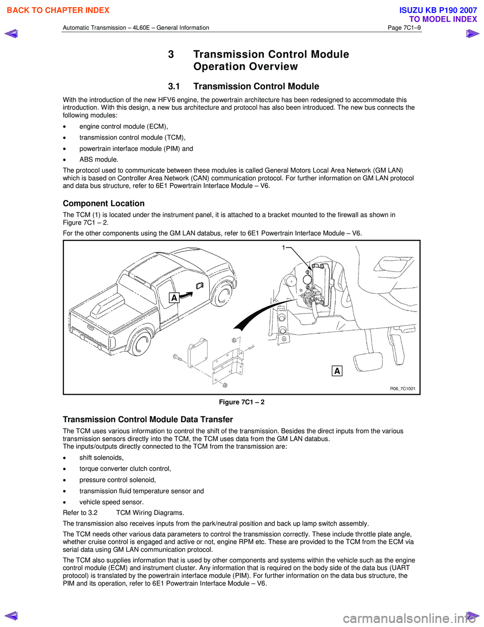
The TCM (1) is located under the instrument panel, it is attached to a bracket mounted to the firewall as shown in
Figure 7C1 – 2.
For the other components using the GM LAN databus, refer to 6E1 Powertrain Interface Module – V6.
Figure 7C1 – 2
Transmission Control Module Data Transfer
The TCM uses various information to control the shift of the transmission. Besides the direct inputs from the various
transmission sensors directly into the TCM, the TCM uses data from the GM LAN databus.
The inputs/outputs directly connected to the TCM from the transmission are:
• shift solenoids,
• torque converter clutch control,
• pressure control solenoid,
• transmission fluid temperature sensor and
• vehicle speed sensor.
Refer to 3.2 TCM Wiring Diagrams.
The transmission also receives inputs from the park/neutral position and back up lamp switch assembly.
The TCM needs other various data parameters to control the transmission correctly. These include throttle plate angle,
whether cruise control is engaged and active or not, engine RPM etc. These are provided to the TCM from the ECM via
serial data using GM LAN communication protocol.
The TCM also supplies information that is used by other components and systems within the vehicle such as the engine
control module (ECM) and instrument cluster. Any information that is required on the body side of the data bus (UART
protocol) is translated by the powertrain interface module (PIM). For further information on the data bus structure, the
PIM and its operation, refer to 6E1 Powertrain Interface Module – V6.
BACK TO CHAPTER INDEX
TO MODEL INDEX
ISUZU KB P190 2007
Page 3773 of 6020
Automatic Transmission – 4L60E – General Information Page 7C1–13
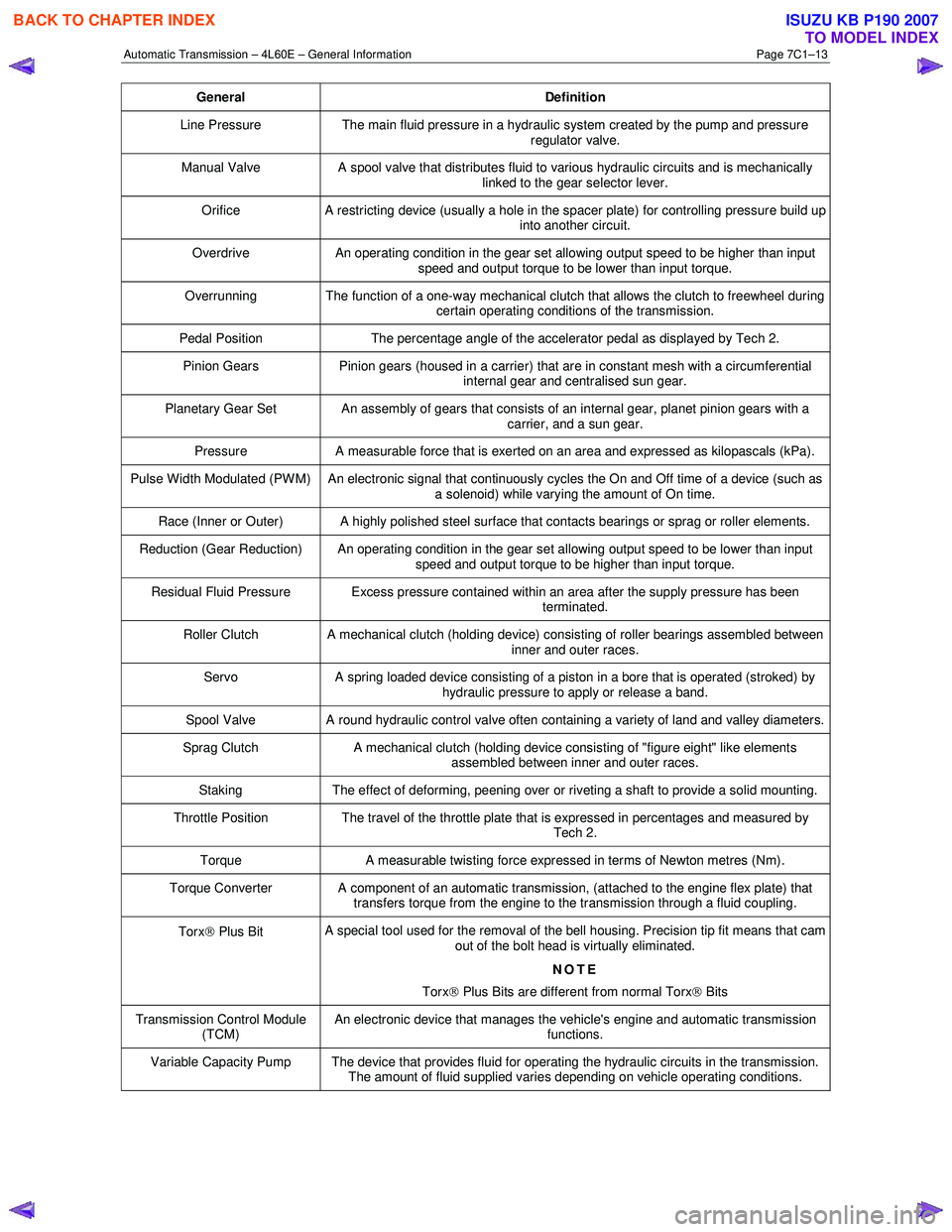
General Definition
Line Pressure The main fluid pressure in a hydraulic system created by the pump and pressure
regulator valve.
Manual Valve A spool valve that distributes fluid to various hydraulic circuits and is mechanically
linked to the gear selector lever.
Orifice A restricting device (usually a hole in the spacer plate) for controlling pressure build up
into another circuit.
Overdrive An operating condition in the gear set allowing output speed to be higher than input
speed and output torque to be lower than input torque.
Overrunning The function of a one-way mechanical clutch that allows the clutch to freewheel during certain operating conditions of the transmission.
Pedal Position The percentage angle of the accelerator pedal as displayed by Tech 2.
Pinion Gears Pinion gears (housed in a carrier) that are in constant mesh with a circumferential
internal gear and centralised sun gear.
Planetary Gear Set An assembly of gears that consists of an internal gear, planet pinion gears with a carrier, and a sun gear.
Pressure A measurable force that is exerted on an area and expressed as kilopascals (kPa).
Pulse Width Modulated (PW M) An electronic signal that continuously cycles the On and Off time of a device (such as
a solenoid) while varying the amount of On time.
Race (Inner or Outer) A highly polished steel surface that contacts bearings or sprag or roller elements.
Reduction (Gear Reduction) An operating condition in the gear set allowing output speed to be lower than input speed and output torque to be higher than input torque.
Residual Fluid Pressure Excess pressure contained within an area after the supply pressure has been terminated.
Roller Clutch A mechanical clutch (holding device) consisting of roller bearings assembled between inner and outer races.
Servo A spring loaded device consisting of a piston in a bore that is operated (stroked) by
hydraulic pressure to apply or release a band.
Spool Valve A round hydraulic control valve often containing a variety of land and valley diameters.
Sprag Clutch A mechanical clutch (holding device consisting of "figure eight" like elements
assembled between inner and outer races.
Staking The effect of deforming, peening over or riveting a shaft to provide a solid mounting.
Throttle Position The travel of the throttle plate that is expressed in percentages and measured by
Tech 2.
Torque A measurable twisting force expressed in terms of Newton metres (Nm).
Torque Converter A component of an automatic transmission, (attached to the engine flex plate) that
transfers torque from the engine to the transmission through a fluid coupling.
Torx Plus Bit A special tool used for the removal of the bell housing. Precision tip fit means that cam
out of the bolt head is virtually eliminated.
NOTE
Torx
Plus Bits are different from normal Torx
Bits
Transmission Control Module
(TCM) An electronic device that manages the vehicle's engine and automatic transmission
functions.
Variable Capacity Pump The device that provides fluid for operating the hydraulic circuits in the transmission. The amount of fluid supplied varies depending on vehicle operating conditions.
BACK TO CHAPTER INDEX
TO MODEL INDEX
ISUZU KB P190 2007
Page 3956 of 6020
Automatic Transmission – 4L60E – On-vehicle Servicing Page 7C4–43
If the verifier disc does not clip into place, the
quick-connect fitting is not engaged, rectify
as required.
10 As a security check, push and clip each verification disc into place over the quick-connect fittings. If difficulty is experienced, repeat the installation process until the verification disc can be clipped into place over the radiator
quick-connect fitting.
11 Snap the outlet cooler line (4) in the clip (5) of the radiator fan shroud.
12 Ensure the routeing of the cooler lines is correct and there is no fouling of the lines.
13 Tighten the screw attaching the cooler lines bracket to the correct torque specifications.
Transmission cooler lines bracket
attaching screw torque specification .................. 23.0 Nm
14 If required, top up the transmission fluid level (cold).
15 Start the engine and check for any fluid leak at the fittings. If a leak is found, stop the engine and rectify the leak.
16 Check and top up the transmission fluid to the correct level as required, refer to 2.1 Transmission Fluid.
3.18 Transmission Assembly
Remove
Disconnection of the battery affects certain
vehicle electronic systems. Refer to 6D1-3
Battery, before disconnecting the battery.
1 Disconnect the battery ground lead.
2 Raise the vehicle and support in a safe manner, refer to 0A General Information for the location of support points.
3 Remove the heat shield from the neutral start and back-up lamp switch, gently prise the selector cable from the transmission external manual shaft linkage and remove the selector cable from the bracket, refer to
3.3 Selector Cable Assembly.
4 Disconnect the harness connectors from the following:
a Vehicle speed sensor, refer to 3.5 Vehicle Speed Sensor.
b Neutral start and back-up switch, refer to 3.4 Neutral Start and Back-up Lamp Switch.
c For the following on four wheel drive vehicles (4W D), refer to 7D Transfer Case and Adaptor Housing:
• neutral switch,
• 2WD – 4WD shift actuator switch,
• speed sensor.
NOTE
If the battery is connected, avoid turning the
ignition switch to the ON position, as the transfer
case control module (TTCM) must first be
removed (memory to be cleared as Check 4W D
Indicator will light).
5 Remove the following components: a Front and centre exhaust assemblies, refer to 6F Exhaust System.
BACK TO CHAPTER INDEX
TO MODEL INDEX
ISUZU KB P190 2007
Page 3960 of 6020
Automatic Transmission – 4L60E – On-vehicle Servicing Page 7C4–47
14 Reconnect the fuel and EVAP pipes three brackets and clips, refer to 6C Fuel System – V6.
15 Reinstall the following components:
a Starter motor, refer to 6D1-2 Starting System.
b Transmission support, refer to 3.7 Transmission Support and Mount.
c Front and centre exhaust assemblies, refer to 6F Exhaust System.
d Rear propeller shaft and for 4WD front propeller shaft, refer to 4A Propeller Shaft.
16 Reconnect the harness connectors to the following: a Vehicle speed sensor, refer to 3.5 Vehicle Speed Sensor.
b Neutral start and back-up switch, refer to 3.4 Neutral Start and Back-up Lamp Switch.
c For the following on 4W D vehicles, refer to 7D Transfer Case and Adaptor Housing:
• neutral switch,
• 2WD – 4WD shift actuator switch,
• speed sensor.
17 Reinstall the selector cable to the transmission external manual shaft linkage, secure the selector cable to the bracket and attach the heat shield to the neutral start and back-up lamp switch, refer to 3.3 Selector Cable
Assembly.
18 Perform a reverse flush of the cooler lines and a flow rate test, refer to 2.2 Reverse Flush and Flow Rate, if either of the following applies:
• the transmission fluid is contaminated,
• the transmission has been replaced,
• the torque converter has been replaced, or
• the transmission oil pump has been replaced.
19 Lower the vehicle to the ground.
20 If required, top up the transmission fluid level (cold).
21 Reconnect the battery ground lead.
22 Start the engine and check for any fluid leaking at the fittings. If a leak is found, stop the engine and rectify the leak.
23 Road test until the transmission has reached operating temperature. Re-check the fluid level and for any fluid leaks, refer to 2.1 Transmission Fluid.
3.19 Transmission Control Module
Remove
1 Ensure the ignition switch is in the OFF position.
2 Disconnect the connector (1) from the transmission control module (TCM) (2) as follows, refer to Figure 7C4 – 63: a remove the securing pin (3),
b press the locking tab and swing the lever (4) to free the connector,
c remove the connector.
3 Remove the four bolts (5) and nuts (6), then the TCM from the mounting bracket (7).
4 If required, remove the two nuts (8) and the mounting bracket from the firewall.
BACK TO CHAPTER INDEX
TO MODEL INDEX
ISUZU KB P190 2007