2007 ISUZU KB P190 transfer control system
[x] Cancel search: transfer control systemPage 1792 of 6020
ENGINE CONTROL SYSTEM (4JK1/4JJ1) 6E-175
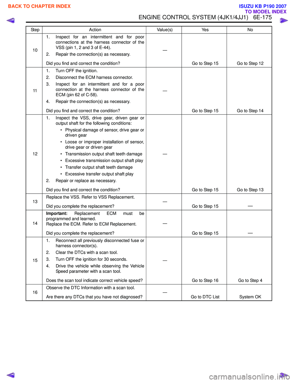
101. Inspect for an intermittent and for poor
connections at the harness connector of the
VSS (pin 1, 2 and 3 of E-44).
2. Repair the connection(s) as necessary.
Did you find and correct the condition? —
Go to Step 15 Go to Step 12
11 1. Turn OFF the ignition.
2. Disconnect the ECM harness connector.
3. Inspect for an intermittent and for a poor connection at the harness connector of the
ECM (pin 62 of C-58).
4. Repair the connection(s) as necessary.
Did you find and correct the condition? —
Go to Step 15 Go to Step 14
12 1. Inspect the VSS, drive gear, driven gear or
output shaft for the following conditions:
• Physical damage of sensor, drive gear or driven gear
• Loose or improper installation of sensor, drive gear or driven gear
• Transmission output shaft teeth damage
• Excessive transmission output shaft play
• Transfer output shaft teeth damage
• Excessive transfer output shaft play
2. Repair or replace as necessary.
Did you find and correct the condition? —
Go to Step 15 Go to Step 13
13 Replace the VSS. Refer to VSS Replacement.
Did you complete the replacement? —
Go to Step 15
—
14Important:
Replacement ECM must be
programmed and learned.
Replace the ECM. Refer to ECM Replacement.
Did you complete the replacement? —
Go to Step 15
—
151. Reconnect all previously disconnected fuse or
harness connector(s).
2. Clear the DTCs with a scan tool.
3. Turn OFF the ignition for 30 seconds.
4. Drive the vehicle while observing the Vehicle Speed parameter with a scan tool.
Does the scan tool indicate correct vehicle speed? —
Go to Step 16 Go to Step 4
16 Observe the DTC Information with a scan tool.
Are there any DTCs that you have not diagnosed? —
Go to DTC List System OK
Step
Action Value(s)Yes No
BACK TO CHAPTER INDEX
TO MODEL INDEX
ISUZU KB P190 2007
Page 1793 of 6020
6E-176 ENGINE CONTROL SYSTEM (4JK1/4JJ1)
DTC P0501 (Flash Code 25)
Circuit Description
The vehicle speed sensor (VSS) is used by the ECM
and speedometer, which generates a speed signal from
the transmission output shaft rotational speed or
transfer output shaft rotational speed. The sensor has
the following circuits.
• Ignition voltage feed circuit
• Low reference circuit
• VSS signal circuit
The VSS uses a hall effect element. It interacts with the
magnetic field created by the rotating magnet and
outputs square wave pulse signal. The ECM calculates
the vehicle speed by the VSS. If the 2WD fitted with
Jatco automatic transmission, VSS signals are sent
from the TCM. If the ECM detects VSS signals are
sharply changed, this DTC will set.
Condition for Running the DTC • The ignition voltage is more than 9 volts.
• The ignition switch is ON.
Condition for Setting the DTC • The ECM detects that the VSS signal are changed larger than a predetermined vehicle speed within a
very short calibrated time. Action Taken When the DTC Sets
• The ECM illuminates the MIL when the diagnostic runs and fails. Refer to DTC Type Definitions for
Action Taken When the DTC Sets - Type A.
• The ECM inhibits cruise control.
Condition for Clearing the DTC • Refer to DTC Type Definitions for Condition for Clearing the MIL/ DTC - Type A.
Diagnostic Aids • If an intermittent condition is suspected, refer to Intermittent Conditions in this section.
• Electromagnetic interference in the VSS circuits may set this DTC.
Notice: • If this DTC set, the Vehicle Speed parameter on the scan tool will display 3 km/h (2 MPH).
Schematic Reference: Engine Controls Schematics
Connector End View Reference: Engine Controls
Connector End Views or ECM Connector End Views
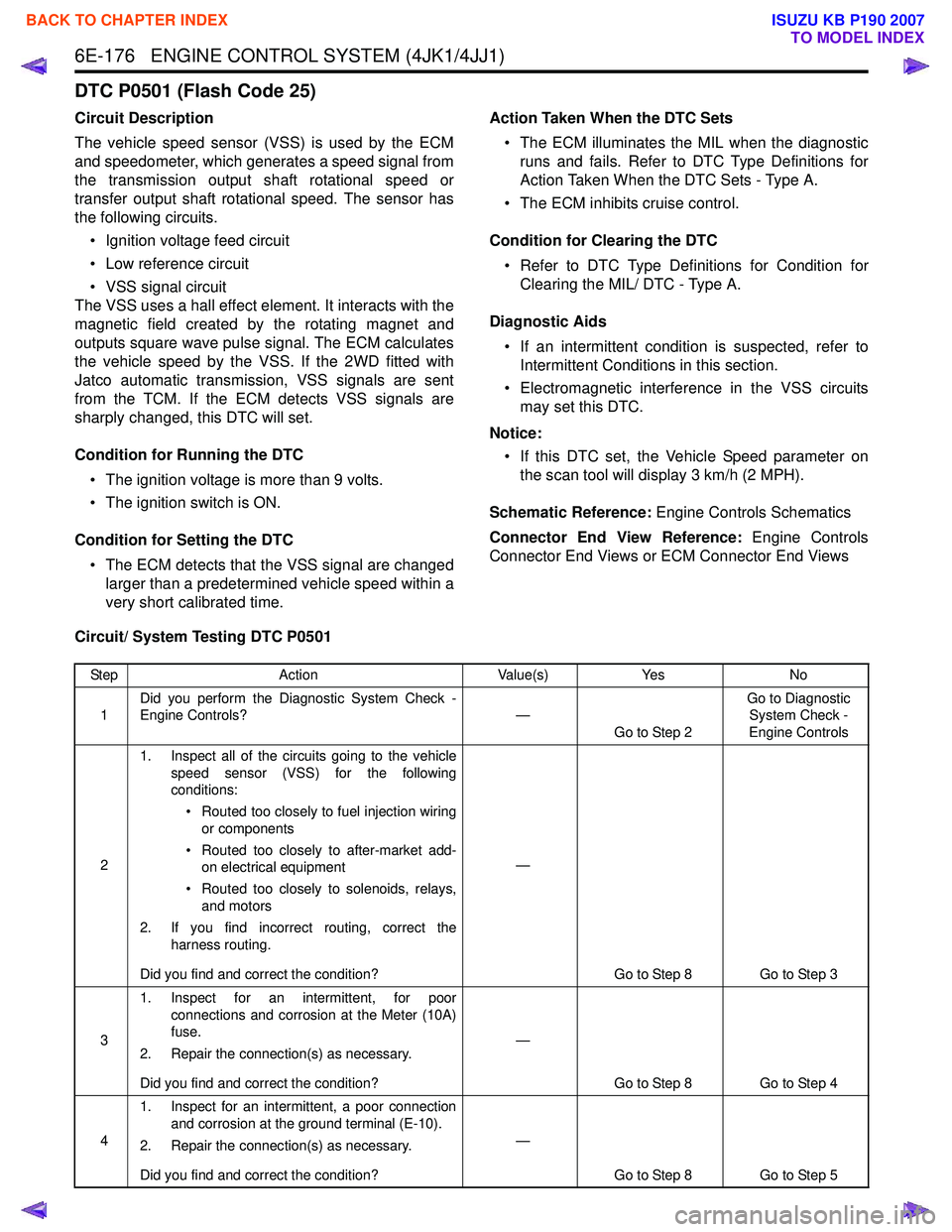
Circuit/ System Testing DTC P0501
Step Action Value(s)Yes No
1 Did you perform the Diagnostic System Check -
Engine Controls? —
Go to Step 2 Go to Diagnostic
System Check -
Engine Controls
2 1. Inspect all of the circuits going to the vehicle
speed sensor (VSS) for the following
conditions:
• Routed too closely to fuel injection wiring or components
• Routed too closely to after-market add- on electrical equipment
• Routed too closely to solenoids, relays, and motors
2. If you find incorrect routing, correct the harness routing.
Did you find and correct the condition? —
Go to Step 8 Go to Step 3
3 1. Inspect for an intermittent, for poor
connections and corrosion at the Meter (10A)
fuse.
2. Repair the connection(s) as necessary.
Did you find and correct the condition? —
Go to Step 8 Go to Step 4
4 1. Inspect for an intermittent, a poor connection
and corrosion at the ground terminal (E-10).
2. Repair the connection(s) as necessary.
Did you find and correct the condition? —
Go to Step 8 Go to Step 5
BACK TO CHAPTER INDEX
TO MODEL INDEX
ISUZU KB P190 2007
Page 1794 of 6020
ENGINE CONTROL SYSTEM (4JK1/4JJ1) 6E-177
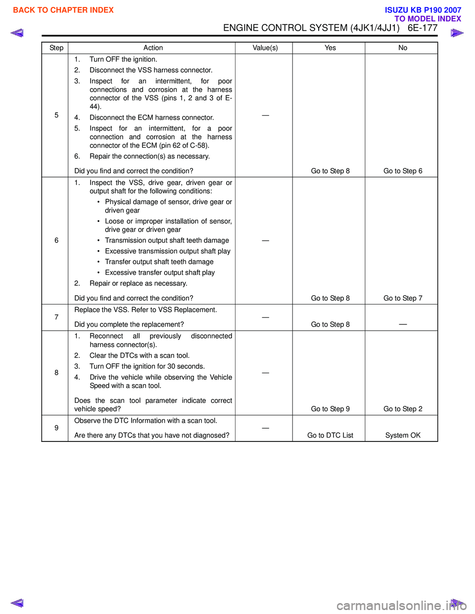
51. Turn OFF the ignition.
2. Disconnect the VSS harness connector.
3. Inspect for an intermittent, for poor connections and corrosion at the harness
connector of the VSS (pins 1, 2 and 3 of E-
44).
4. Disconnect the ECM harness connector.
5. Inspect for an intermittent, for a poor connection and corrosion at the harness
connector of the ECM (pin 62 of C-58).
6. Repair the connection(s) as necessary.
Did you find and correct the condition? —
Go to Step 8 Go to Step 6
6 1. Inspect the VSS, drive gear, driven gear or
output shaft for the following conditions:
• Physical damage of sensor, drive gear or driven gear
• Loose or improper installation of sensor, drive gear or driven gear
• Transmission output shaft teeth damage
• Excessive transmission output shaft play
• Transfer output shaft teeth damage
• Excessive transfer output shaft play
2. Repair or replace as necessary.
Did you find and correct the condition? —
Go to Step 8 Go to Step 7
7 Replace the VSS. Refer to VSS Replacement.
Did you complete the replacement? —
Go to Step 8
—
81. Reconnect all previously disconnected
harness connector(s).
2. Clear the DTCs with a scan tool.
3. Turn OFF the ignition for 30 seconds.
4. Drive the vehicle while observing the Vehicle Speed with a scan tool.
Does the scan tool parameter indicate correct
vehicle speed? —
Go to Step 9 Go to Step 2
9 Observe the DTC Information with a scan tool.
Are there any DTCs that you have not diagnosed? —
Go to DTC List System OK
Step
Action Value(s)Yes No
BACK TO CHAPTER INDEX
TO MODEL INDEX
ISUZU KB P190 2007
Page 1966 of 6020
ENGINE CONTROL SYSTEM (4JK1/4JJ1) 6E-349
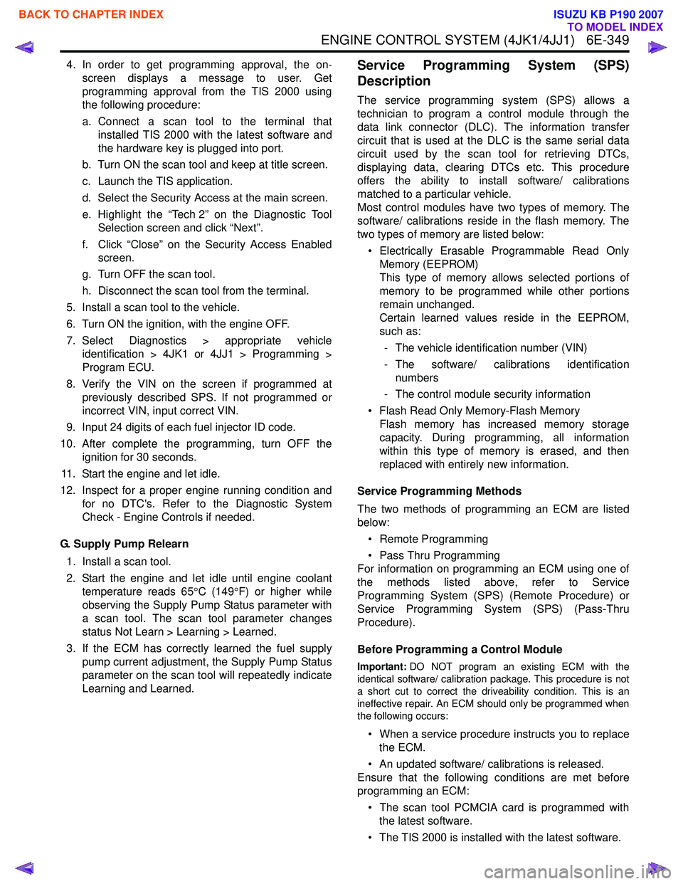
4. In order to get programming approval, the on-screen displays a message to user. Get
programming approval from the TIS 2000 using
the following procedure:
a. Connect a scan tool to the terminal that installed TIS 2000 with the latest software and
the hardware key is plugged into port.
b. Turn ON the scan tool and keep at title screen.
c. Launch the TIS application.
d. Select the Security Access at the main screen.
e. Highlight the “Tech 2” on the Diagnostic Tool Selection screen and click “Next”.
f. Click “Close” on the Security Access Enabled screen.
g. Turn OFF the scan tool.
h. Disconnect the scan tool from the terminal.
5. Install a scan tool to the vehicle.
6. Turn ON the ignition, with the engine OFF.
7. Select Diagnostics > appropriate vehicle identification > 4JK1 or 4JJ1 > Programming >
Program ECU.
8. Verify the VIN on the screen if programmed at previously described SPS. If not programmed or
incorrect VIN, input correct VIN.
9. Input 24 digits of each fuel injector ID code.
10. After complete the programming, turn OFF the ignition for 30 seconds.
11. Start the engine and let idle.
12. Inspect for a proper engine running condition and for no DTC's. Refer to the Diagnostic System
Check - Engine Controls if needed.
G. Supply Pump Relearn 1. Install a scan tool.
2. Start the engine and let idle until engine coolant temperature reads 65 °C (149 °F) or higher while
observing the Supply Pump Status parameter with
a scan tool. The scan tool parameter changes
status Not Learn > Learning > Learned.
3. If the ECM has correctly learned the fuel supply pump current adjustment, the Supply Pump Status
parameter on the scan tool will repeatedly indicate
Learning and Learned.Service Programming System (SPS)
Description
The service programming system (SPS) allows a
technician to program a control module through the
data link connector (DLC). The information transfer
circuit that is used at the DLC is the same serial data
circuit used by the scan tool for retrieving DTCs,
displaying data, clearing DTCs etc. This procedure
offers the ability to install software/ calibrations
matched to a particular vehicle.
Most control modules have two types of memory. The
software/ calibrations reside in the flash memory. The
two types of memory are listed below:
• Electrically Erasable Programmable Read Only Memory (EEPROM)
This type of memory allows selected portions of
memory to be programmed while other portions
remain unchanged.
Certain learned values reside in the EEPROM,
such as:
- The vehicle identification number (VIN)
- The software/ calibrations identification numbers
- The control module security information
• Flash Read Only Memory-Flash Memory Flash memory has increased memory storage
capacity. During programming, all information
within this type of memory is erased, and then
replaced with entirely new information.
Service Programming Methods
The two methods of programming an ECM are listed
below:
• Remote Programming
• Pass Thru Programming
For information on programming an ECM using one of
the methods listed above, refer to Service
Programming System (SPS) (Remote Procedure) or
Service Programming System (SPS) (Pass-Thru
Procedure).
Before Programming a Control Module
Important: DO NOT program an existing ECM with the
identical software/ calibration package. This procedure is not
a short cut to correct the driveability condition. This is an
ineffective repair. An ECM should only be programmed when
the following occurs:
• When a service procedure instructs you to replace the ECM.
• An updated software/ calibrations is released.
Ensure that the following conditions are met before
programming an ECM:
• The scan tool PCMCIA card is programmed with the latest software.
• The TIS 2000 is installed with the latest software.
BACK TO CHAPTER INDEX
TO MODEL INDEX
ISUZU KB P190 2007
Page 1967 of 6020
6E-350 ENGINE CONTROL SYSTEM (4JK1/4JJ1)
• The hardware key is plugged into the computerport.
• Vehicle system voltage: - There are no charging system concerns. Allcharging system concerns must be repaired
before programming the ECM.
- The battery voltage is greater than 12 volts but less than 16 volts. The battery must be fully
charged before programming the ECM.
- A battery charger is NOT connected to the vehicles battery. Incorrect system voltage or
voltage fluctuations from a battery charger may
cause programming failure or ECM damage.
- Turn OFF or disable any system that may put a load on the vehicles battery. Turn OFF or
disable systems such as:
◊ Heating, ventilation, and air conditioning
(HVAC) systems
◊ Headlights
◊ Room lights
◊ Accessory equipment
• The ignition switch is in the proper position. The scan tool prompts you to turn ON the ignition, with
the engine OFF. DO NOT change the position of
the ignition switch during the programming
procedure unless instructed to do so.
• All tool connections are secure: - The RS-232 cable
- The connection at the DLC
- The voltage supply circuits
• DO NOT disturb the tool harnesses while programming. If an interruption occurs during the
programming procedure, programming failure or
ECM damage may occur.
• If you are performing the Pass-Thru programming procedure using a notebook computer without the
power cord, ensure that the internal battery is fully
charged.
Service Programming System (SPS)
(Remote Procedure)
Notice: Some module will not accept SPS remote
procedure using 10MB PCMCIA card. In such case,
use 32MB PCMCIA card or SPS pass-thru procedure.
The Remote SPS method is a three-step process that
involves the following procedures:
1. Connecting the scan tool to the vehicle and obtaining the information from the ECM.
2. Connecting the scan tool to the terminal and downloading a new calibration file from the
terminal into the scan tool memory.
3. Reconnecting the scan tool to the vehicle and uploading the new calibration file into the ECM. Performing the Remote Procedure
1. Connect a scan tool to the vehicle and obtain the ECM information using the following procedure:
Notice: Ensure the ECM is installed in the vehicle and
the battery is fully charged before programming.
a. Install a scan tool.
b. Turn ON the ignition, with the engine OFF.
c. Select Service Programming System (SPS) > Request Info.
d. If there is already stored in the scan tool, the existing data is displayed on the screen. The
scan tool asks user to keep existing data "Keep
Data" or "Continue" to request new vehicle
information from the ECM. If there is no data in
the scan tool, it will immediately start vehicle
identification.
e. Select the vehicle description by following the on-screen instructions based on stamped VIN
or affixed VIN plate on the vehicle.
f. During obtaining information, the scan tool is receiving information from all modules at the
same time. But only ECM information is
displayed on the screen.
g. Turn OFF all accessories and press "Okay".
h. Verify that the correct VIN is displayed on the scan tool. If the VIN is incorrect or no VIN,
record the correct VIN.
2. Turn OFF the ignition.
3. Turn OFF the scan tool and disconnect from the vehicle.
4. Transfer the data from the terminal to the scan tool using the following procedure:
Notice: The TIS supports service programming with
the Tech 2 scan tool only.
a. Connect the scan tool to the terminal.
b. Launch the TIS application.
c. Select the Service Programming System at the main screen.
d. Highlight the following information on the Select Diagnostic Tool and Programming Process
screen, then click "Next".
• Select Diagnostic Tool - Tech 2
• Select Programming Process - Identify whether an existing ECM is being
reprogrammed or an ECM is being replaced
with a new one
• Select ECU Location - Vehicle
e. Verify the connections on the Preparing for Communication screen, then click "Next".
f. Verify the VIN on the Validate Vehicle Identification Number (VIN) screen, then click
"Next".
BACK TO CHAPTER INDEX
TO MODEL INDEX
ISUZU KB P190 2007
Page 1968 of 6020
ENGINE CONTROL SYSTEM (4JK1/4JJ1) 6E-351
Notice:If the ECM is replaced to new one, VIN does
not displayed. Input correct VIN reading from stamped
VIN or affixed VIN plate on the vehicle. If the ECM from
another vehicle is installed, input correct VIN by same
way.
g. Highlight Engine on the Select System Typescreen, then click "Next", if on-screen
instruction displayed.
h. Complete the following information based on the service ID plate on the Validate Vehicle
Data screen until "Next" is highlighted, then
click "Next".
• Model
• Model year
• Engine type
• Model designator
• Destination code
• Transmission type
i. Verify your selection on the Summary screen.
Notice: Refer to Service Bulletin and Description
column before service programming is performed if the
bulletins are listed along with the calibration files.
Notice: Select Cancel if you receive a message stating
that the calibration selected is already the current
calibration in the ECM and reprogramming with the
same download is not allowed.
j. Click "Reprog".
k. The Transfer Data screen will appear until the progress bar reaches 100%.
5. Close the application and return to the TIS application selection screen after the download is
completed.
6. Turn OFF the scan tool and disconnect from the terminal.
7. Transfer the data from the scan tool to the ECM using the following procedure:
a. Install a scan tool.
b. Turn ON the ignition, with the engine OFF.
c. Select Service Programming System (SPS) > Program ECU.
d. Turn OFF all accessories and press "Continue".
e. Programming in Process will appear until the progress bar reaches 100%.
Notice: Some warning lamp may turn ON or blink while
programming the ECM since communication between
the ECM and other modules are interrupted. Clear DTC
in any module after programming.
f. Press "Continue" and exit the program after thescan tool displays "Programming Was
Successful".
8. Turn OFF the ignition.
9. Turn OFF the scan tool and disconnect from the vehicle.Service Programming System (SPS) (Pass-
Thru Procedure)
Pass-Thru programming allows the scan tool to remain
connected to the terminal and to the vehicle throughout
the programming process. The vehicle must be in close
proximity to the terminal while using Pass-Thru.
1. Launch the TIS application.
2. Select the Service Programming System at the main screen.
3. Highlight the following information on the Select Diagnostic Tool and Programming Process screen,
then click "Next":
• Select Diagnostic Tool-Select Pass - Thru
• Select Programming Process - Identify whether as existing ECM is being reprogrammed or an
ECM is being replaced with a new one.
• Select ECU Location - Vehicle
4. Complete all vehicle data on the Preparing for Communication/ Determine Vehicle screen until
"Next" is highlighted, then click "Next".
5. Follow the instruction on the Preparing for Communication screen, then click "Next".
Notice: In order to reduce the potential for signal loss,
the RS-232 cable should not be more than 25 feet long.
6. Verify the VIN on the Validate Vehicle Identification Number (VIN) screen, then click "Next".
Notice: If the ECM is replaced to new one, VIN does
not displayed. Input correct VIN reading from stamped
VIN or affixed VIN plate on the vehicle. If the ECM from
another vehicle is installed, input correct VIN by same
way.
7. Highlight Engine on the Select System Type screen, then click "Next", if on-screen instruction
displayed.
8. Complete the following information based on the service ID plate on the Validate Vehicle Data
screen until "Next" is highlighted, then click "Next".
• Model
• Model year
• Engine type
• Model designator
• Destination code
• Transmission type
9. Verify your selection on the Summary screen.
Notice: Refer to Service Bulletin and Description
column before service programming is performed if the
bulletins are listed along with the calibration files.
Notice: Select Cancel if you receive a message stating
that the calibration selected is already the current
calibration in the ECM and reprogramming with the
same download is not allowed.
10. Click "Reprog".
BACK TO CHAPTER INDEX
TO MODEL INDEX
ISUZU KB P190 2007
Page 1969 of 6020
6E-352 ENGINE CONTROL SYSTEM (4JK1/4JJ1)
11. The Transfer Data screen will appear until theprogress bar reaches 100%.
Notice: Some warning lamp may turn ON or blink while
programming the ECM since communication between
the ECM and other modules are interrupted. Clear DTC
in any module after programming.
12. Close the application and return to the TIS application selection screen after the download is
completed.
13. Turn OFF the ignition.
14. Turn OFF the scan tool and disconnect from the vehicle.
BACK TO CHAPTER INDEX
TO MODEL INDEX
ISUZU KB P190 2007
Page 2227 of 6020
ENGINE DRIVEABILITY AND EMISSIONS 6E–57
GENERAL DESCRIPTION FOR
EVAPORATIVE EMISSION SYSTEM
EVAP Emission Control System Purpose
The basic evaporative emission control system used on
the charcoal canister storage method. The method
transfers fuel vapor from the fuel tank to an activated
carbon (charcoal) storage devise to hold the vapors
when the vehicle is not operating.
The canister is located on the rear axle housing by the
frame cross-member.
When the engine is running, the fuel vapor is purged
from the carbon element by intake air flow and
consumed in the normal combustion process.
EVAP Emission Control System Operation
The EVAP canister purge is controlled by a solenoid
valve that allows the manifold vacuum to purge the
canister. The engine control module (ECM) supplies a
ground to energize the solenoid valve (purge on). The
EVAP purge solenoid control is pulse-width modulated
(PWM) (turned on and off several times a second). The
duty cycle (pulse width) is determined by engine
operating conditions including load, throttle position,
coolant temperature and ambient temperature. The duty
cycle is calculated by the ECM. the output is
commanded when the appropriate conditions have
been met. These conditions are:
• The engine is fully warmed up.
• The engine has been running for a specified time.
• The IAT reading is above 10°C (50°F).
• Purge/Vacuum Hoses. Made of rubber compounds, these hoses route the gasoline fumes from their
sources to the canister and from the canister to the
intake air flow.
• EVAP Canister. Mounted on a bracket ahead of the fuel tank, the canister stores fuel vapors until the
ECM determined that engine conditions are right for
them to be removed and burned.
Poor idle, stalling and Poor driveability can be caused
by:
• A malfunctioning purge solenoid.
• A damaged canister.
• Hoses that are split, cracked, or not connected properly.
System Fault Detection
The EVAP leak detection strategy is based on applying
vacuum to the EVAP system and monitoring vacuum
decay. At an appropriate time, the EVAP purge solenoid
is turned “ON,” allowing the engine vacuum to draw a
small vacuum on the entire evaporative emission
system.
After the desired vacuum level has been achieved, the
EVAP purge solenoid is turned “OFF,” sealing the
system. A leak is detected by monitoring for a decrease
in vacuum level over a given time period, all other
variables remaining constant.
If the desired vacuum level cannot be achieved in the
test described above, a large leak or a faulty EVAP
purge control solenoid valve is indicated.
Leaks can be caused by the following conditions:
• Missing or faulty fuel cap
• Disconnected, damaged, pinched, or blocked EVAP purge line
• Disconnected, damaged, pinched, or blocked fuel tank vapor line
• Disconnected or faulty EVAP purge control solenoid valve
• Open ignition feed circuit to the purge solenoid
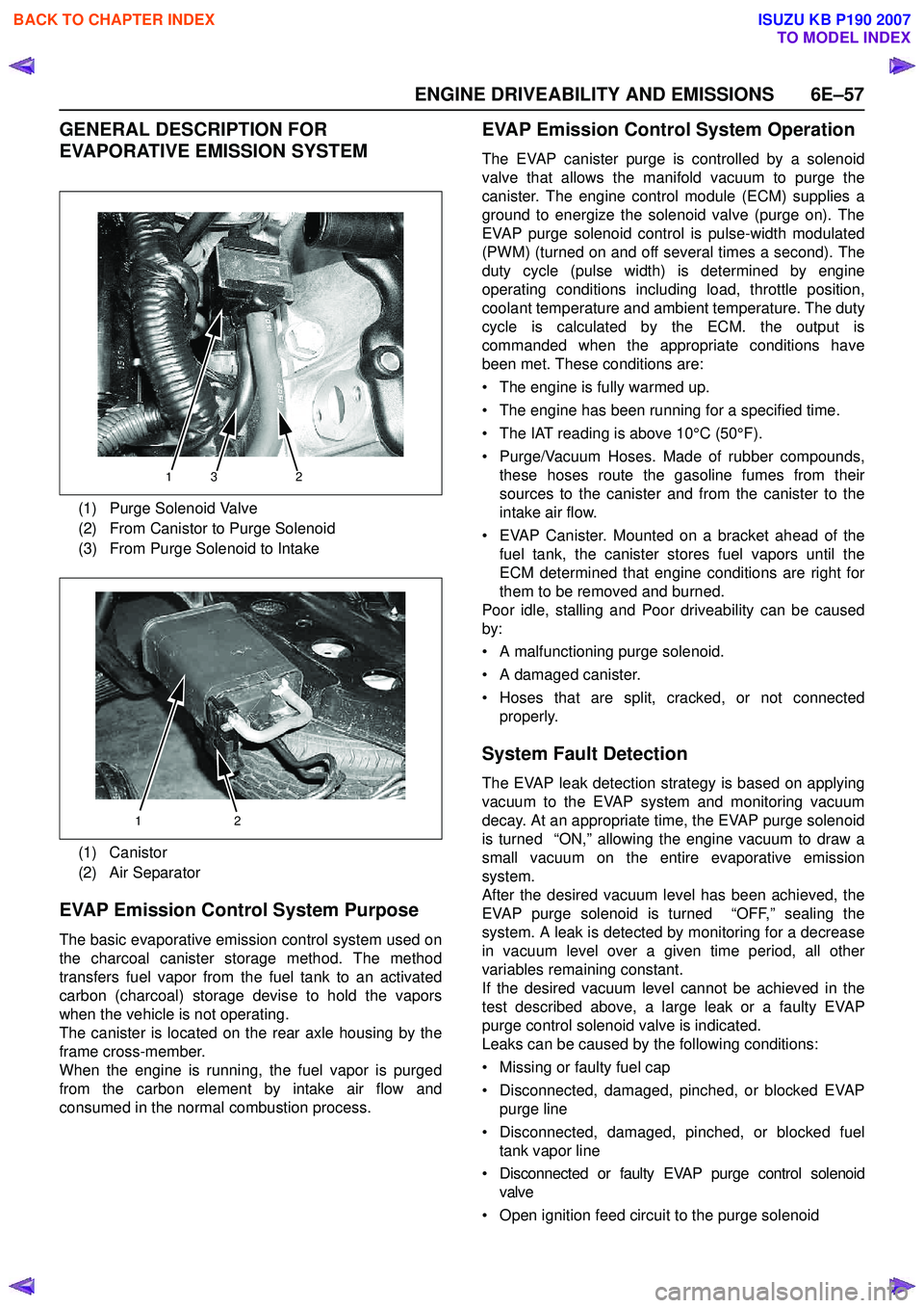
(1) Purge Solenoid Valve
(2) From Canistor to Purge Solenoid
(3) From Purge Solenoid to Intake
(1) Canistor
(2) Air Separator
132
12
BACK TO CHAPTER INDEX
TO MODEL INDEX
ISUZU KB P190 2007