2007 ISUZU KB P190 key battery
[x] Cancel search: key batteryPage 5476 of 6020
8A-538 ELECTRICAL-BODY AND CHASSIS
TROUBLESHOOTING
Diagnostic procedure
•
Check the operation "Lock / unlock" by using
transmitter (remote key) on the vehicle.
• Check the operation "ON / OFF" for Driver side
door SW on the vehicle.
• Perform the Keyless entry System Check.
Diagnostic Aids
An intermittent may be caused by the following:
• Poor connections.
• Miss routed harness.
• Rubbed through wire insulation.
• Broken wire inside the insulation.
Check for the following conditions:
• Poor connection at keyless entry control unit-
Inspect harness connectors for backed out
terminals, improper mating, broken locks,
improperly formed or damaged terminals, and poo
r
terminal to wire connection.
• Damaged harness-Inspect the wiring harness fo
r
damage.
Check the Electro-Magnetic Interference (EMI)
• Location of vehicle check
Move the vehicle to a new location and perform
the check again.
• Non-OEM Parts.
Switch is “OFF” or remove the Non-OEM parts and
perform the check again.
• Other
Remove the accessory and another key from key.
Check the other items.
• Battery voltage is low.
• Keyless entry programming functions.
• Registration for security code.
• Ignition switch operation.
• Meter system is malfunction.
Check the operation
Check the operation "Lock / unlock" by using
transmitter (remote key) on the vehicle.
Notice
If so equipped the Anti Theft, Refer to ANTI
THEFT SYSTEM in 11B Section.
BACK TO CHAPTER INDEX TO MODEL INDEXISUZU KB P190 2007
Page 5481 of 6020
ELECTRICAL-BODY AND CHASSIS 8A-543
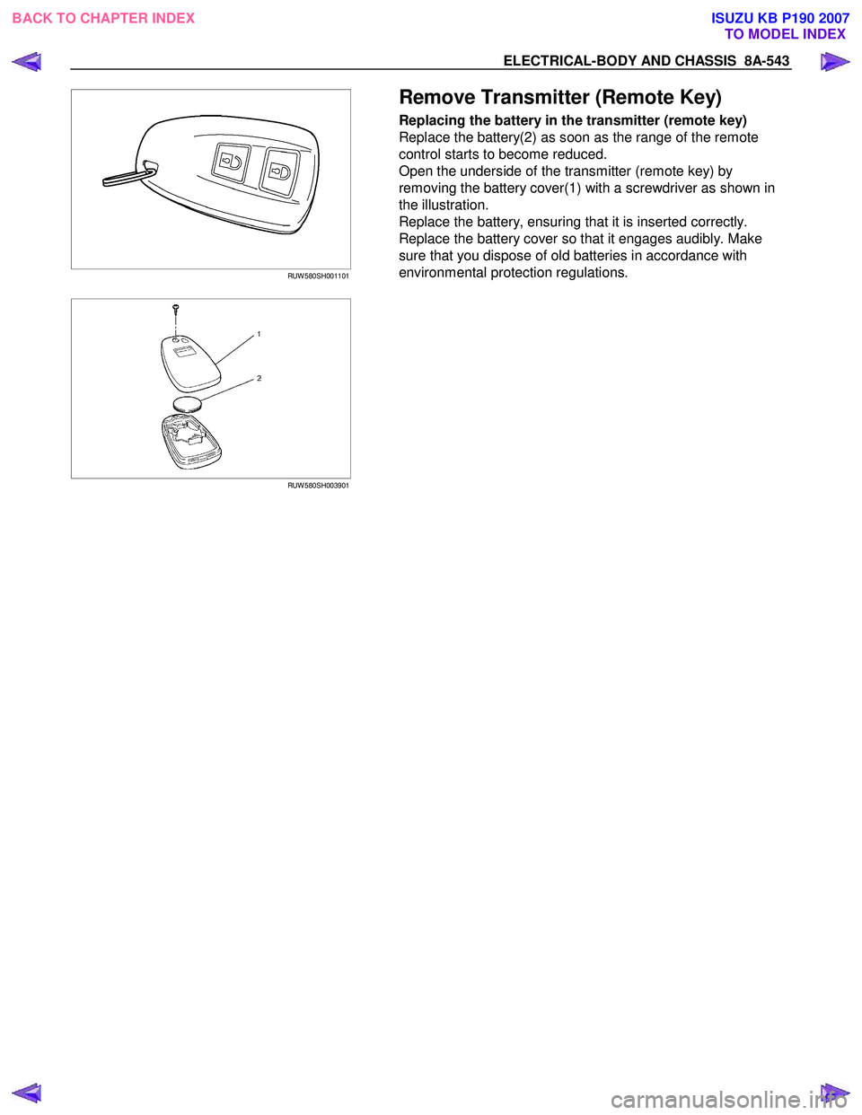
RUW 580SH001101
Remove Transmitter (Remote Key)
Replacing the battery in the transmitter (remote key)
Replace the battery(2) as soon as the range of the remote
control starts to become reduced.
Open the underside of the transmitter (remote key) by
removing the battery cover(1) with a screwdriver as shown in
the illustration.
Replace the battery, ensuring that it is inserted correctly.
Replace the battery cover so that it engages audibly. Make
sure that you dispose of old batteries in accordance with
environmental protection regulations.
RUW 580SH003901
BACK TO CHAPTER INDEX
TO MODEL INDEXISUZU KB P190 2007
Page 5483 of 6020
ELECTRICAL-BODY AND CHASSIS 8A-545
Power Door Lock System
General Description
The circuit consists of the door lock (& power window)
switch, door lock actuator for the front and rear door,
tailgate lock actuator and the door lock key switch.
The front door lock switch ‐RH is always provided with
the battery voltage.
The key or the inside lock button on both driver's and
front passenger's door can activate the lock mechanism
of all the doors (including the tailgate).
W hen the driver's door lock switch or the front
passenger's door lock switch is turned on, current flows
for about one second to the door lock actuator of each
door connected in parallel with the front door lock (&
power window) switch ‐LH to activate the actuator to
lock and unlock the doors.
Door Lock Key Switch
Removal and Installation
・ Refer to the Front Door Lock Assembly removal
and installation steps in this section.
Front Door Lock Actuator
Removal and Installation
・ Refer to the Front Door Lock Assembly removal
and installation steps in this section.
Rear Door Lock Actuator
Removal and Installation
・ Refer to the Rear Door Lock Assembly removal
and installation steps in this section.
Tailgate Lock Actuator
Removal and Installation
・ Refer to the Tailgate Lock Assembly removal and
installation steps in this section.
BACK TO CHAPTER INDEX TO MODEL INDEXISUZU KB P190 2007
Page 5485 of 6020
ELECTRICAL-BODY AND CHASSIS 8A-547
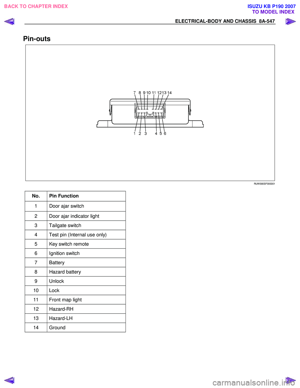
Pin-outs
RUW 580SF000301
No. Pin Function
1 Door ajar switch
2 Door ajar indicator light
3 Tailgate switch
4 Test pin (Internal use only)
5 Key switch remote
6 Ignition switch
7 Battery
8 Hazard battery
9 Unlock
10 Lock
11 Front map light
12 Hazard-RH
13 Hazard-LH
14 Ground
BACK TO CHAPTER INDEX TO MODEL INDEXISUZU KB P190 2007
Page 5517 of 6020

ELECTRICAL-BODY AND CHASSIS 8A-579
Remote key
Remove Key Assembly
Replacing the battery in the remote control unit
Replace the battery as soon as the range of the remote control
starts to become reduced.
Open the underside of the remote control unit by removing the
battery cover with a screwdriver as shown in the illustration.
Replace the battery, ensuring that it is inserted correctly.
Replace the battery cover so that it engages audibly. The
battery change must be performed within 3 minutes, otherwise
the remote control will have to be reprogrammed. Make sure
that you dispose of old batteries in accordance with
environmental protection regulations.
604RW 055
BACK TO CHAPTER INDEX TO MODEL INDEXISUZU KB P190 2007
Page 5651 of 6020
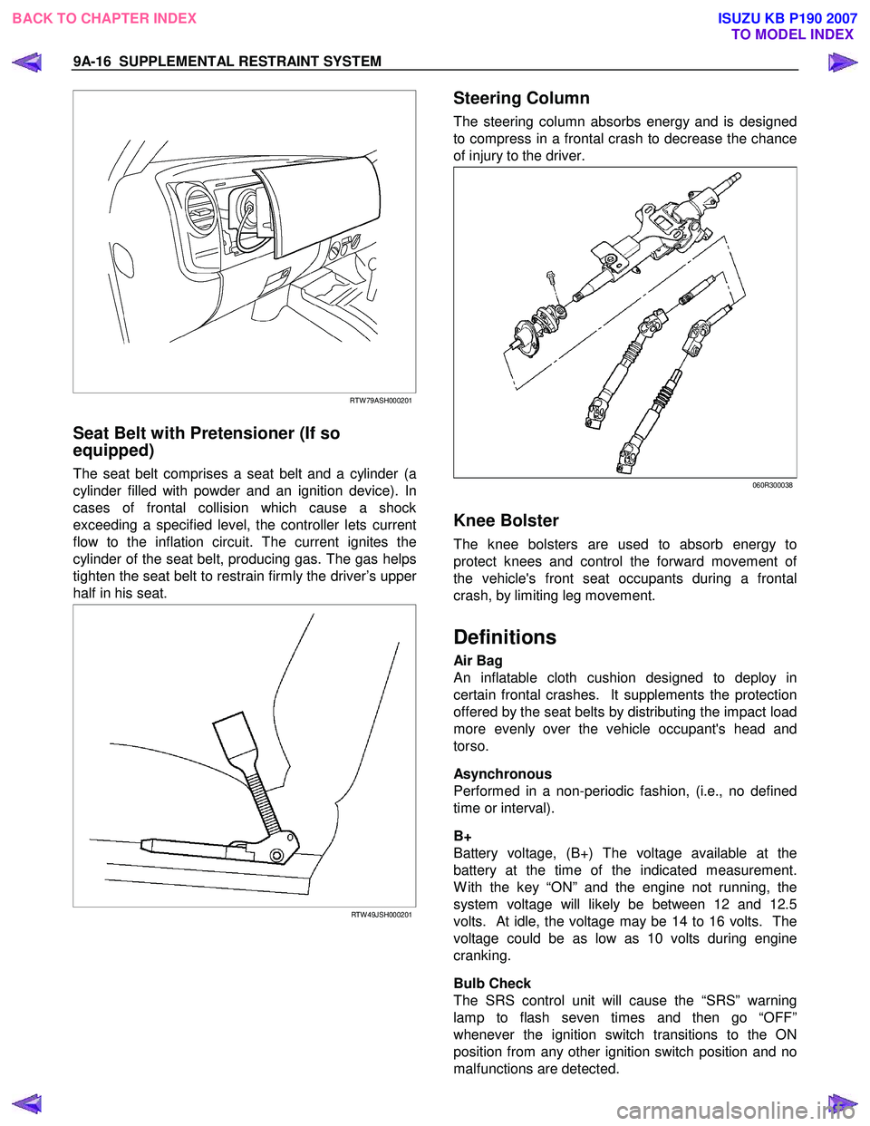
9A-16 SUPPLEMENTAL RESTRAINT SYSTEM
RTW 79ASH000201
Seat Belt with Pretensioner (If so
equipped)
The seat belt comprises a seat belt and a cylinder (a
cylinder filled with powder and an ignition device). In
cases of frontal collision which cause a shock
exceeding a specified level, the controller lets current
flow to the inflation circuit. The current ignites the
cylinder of the seat belt, producing gas. The gas helps
tighten the seat belt to restrain firmly the driver’s uppe
r
half in his seat.
RTW 49JSH000201
Steering Column
The steering column absorbs energy and is designed
to compress in a frontal crash to decrease the chance
of injury to the driver.
060R300038
Knee Bolster
The knee bolsters are used to absorb energy to
protect knees and control the forward movement o
f
the vehicle's front seat occupants during a frontal
crash, by limiting leg movement.
Definitions
Air Bag
An inflatable cloth cushion designed to deploy in
certain frontal crashes. It supplements the protection
offered by the seat belts by distributing the impact load
more evenly over the vehicle occupant's head and
torso.
Asynchronous
Performed in a non-periodic fashion, (i.e., no defined
time or interval).
B+
Battery voltage, (B+) The voltage available at the
battery at the time of the indicated measurement.
W ith the key “ON” and the engine not running, the
system voltage will likely be between 12 and 12.5
volts. At idle, the voltage may be 14 to 16 volts. The
voltage could be as low as 10 volts during engine
cranking.
Bulb Check
The SRS control unit will cause the “SRS” warning
lamp to flash seven times and then go “OFF”
whenever the ignition switch transitions to the ON
position from any other ignition switch position and no
malfunctions are detected.
BACK TO CHAPTER INDEX TO MODEL INDEXISUZU KB P190 2007
Page 5656 of 6020
SUPPLEMENTAL RESTRAINT SYSTEM 9A-21
On–Vehicle Service
Service Precaution
WARNING: WHEN PERFORMING SERVICE ON OR
AROUND SRS COMPONENTS OR SRS WIRING,
FOLLOW THE PROCEDURES LISTED BELOW TO
TEMPORARILY DISABLE THE SRS. FAILURE TO
FOLLOW PROCEDURES COULD RESULT IN
POSSIBLE AIR BAG DEPLOYMENT, PERSONAL
INJURY OR OTHERWISE UNNECESSARY SRS
REPAIRS.
The SRS control unit in Driver–Passenger SRS can
maintain sufficient voltage to cause a deployment fo
r
up to 15 seconds after the ignition switch is turned
“OFF,” the battery is disconnected, or the fuse
powering the SRS control unit is removed.
Many of the service procedures require removal of the
“SRS” fuse, and disconnection of the air bag assembl
y
from the deployment loop to avoid an accidental
deployment. If the air bag assembly is disconnected
from the deployment loop as noted in the “Disabling
the SRS” procedure that follows, service can begin
immediately without waiting for the 15 second time
period to expire.
Disabling The SRS
Removal
Turn the ignition switch to “LOCK” and remove the
key.
1. Remove the SRS fuse “SRS”, from the side of the driver’s side of the instrument panel fuse block o
r
disconnect the battery.
2. Disconnect the yellow connector at the base of the steering column.
3. Remove the glove box assembly, refer to “Passenger Air Bag Assembly Replacement” in
this manual.
4. Disconnect the yellow connector behind the glove box assembly.
CAUTION: With the “SRS” fuse removed and
ignition switched “ON”, the “SRS” warning lamp
will be “ON”. This is normal operation and does
not indicate an SRS malfunction.
Enabling The SRS
Installation
CAUTION: Never use the air bag assembly from
another vehicle or different model year air bag
assembly.
Use only a new air bag assembly matched to the
TFR/S which is being repaired.
Turn the ignition switch to “LOCK” and remove the
key.
1. Connect the yellow connector passenger air bag assembly.
2. Install the glove box assembly. Refer to “Passenger air bag assembly replacement” in this
manual.
3. Connect the yellow connector at the base of the steering column.
4. Install the “AIR BAG” fuse “SRS” to the side of the driver’s side of the instrument panel fuse block o
r
connect the battery.
Turn the ignition switch to “ON” and verify that the
“SRS” warning lamp flashes seven times and then
turns to “LOCK”. If it does not operate as described,
perform the “SRS Diagnostic System Check” in this
manual.
Handling / Installation / Diagnosis
1. The air bag assembly should not be subjected to temperatures above 65
°C (150°F).
2. The air bag assembly, and SRS control unit, should not be used if they have been dropped from
a height of 100 centimeters (3.28 feet) or more.
3. W hen the SRS control unit is replaced, it must be oriented with the arrow on the sensor pointing
toward the front of the vehicle. It is very important
for the SRS control unit to be located flat on the
mounting surface, parallel to the vehicle datum
line. It is important that the SRS control unit
mounting surface is free of any dirt or other foreign
material.
4. Do not apply power to the SRS unless all components are connected or a diagnostic chart
requests it, as this will set a diagnostic trouble
code.
5. The “SRS Diagnostic System Check” must be the starting point of any SRS diagnostics. The “SRS
Diagnostic System Check” will verify proper “SRS”
warning lamp operation and will lead you to the
correct chart to diagnose any SRS malfunctions.
Bypassing these procedures may result in
extended diagnostic time, incorrect diagnosis, and
incorrect parts replacement.
BACK TO CHAPTER INDEX TO MODEL INDEXISUZU KB P190 2007
Page 5667 of 6020
9A-32 SUPPLEMENTAL RESTRAINT SYSTEM
Service Precautions for SRS
Component Service
CAUTION: When fasteners are removed, always
reinstall them at the same location from which
they were removed. If a fastener needs to be
replaced, use the correct part number fastener fo
r
that application. If the correct part number
fastener is not available, a fastener of equal size
and strength (or stronger) may be used. Fasteners
that are not reused, and those requiring a thread
locking compound will be called out. The correct
torque value must be used when installing
fasteners that require it. If the above conditions
are not followed, parts or system damage could
result.
WARNING: WHEN PERFORMING SERVICE ON OR
AROUND SRS COMPONENTS OR SRS WIRING,
FOLLOW THE PROCEDURES LISTED BELOW TO
TEMPORARILY DISABLE THE SRS. FAILURE TO
FOLLOW PROCEDURES COULD RESULT IN
POSSIBLE AIR BAG DEPLOYMENT, PERSONAL
INJURY OR OTHERWISE UNNEEDED SRS
REPAIRS.
The SRS control unit in the Driver–Passenger SRS
can maintain sufficient voltage to cause a deployment
for up to 15 seconds after the ignition switch is turned
“OFF,” the battery is disconnected, or the fuse
powering the SRS control unit is removed.
Many of the service procedures require removal of the
“SRS” fuse, and disconnection of the air bag assembl
y
from the deployment loop to avoid an accidental
deployment. If the air bag assembly is disconnected
from the deployment loop as noted in the “Disabling
the SRS” procedure that follows, service can begin
immediately without waiting for the 15 second time
period to expire.
Disabling The SRS
Removal
Turn the ignition switch to “OFF” and turn the steering
wheel so that the vehicle's wheels are pointing straight
ahead.
1. Remove the SRS fuse “SRS” from the left dash side lower fuse block or disconnect the battery.
2. Disconnect the yellow connector at the base o
f
steering column.
3. Remove the glove box assembly; Refer to “Passenger air bag assembly replacement” in this
section.
4. Disconnect the passenger air bag assembly yello
w
connector behind the glove box assembly.
CAUTION: With the “SRS” fuse removed and the
ignition switch to “ON,” the “SRS” warning lamp
will be “ON.” This is normal operation and does
not indicate an SRS malfunction.
Enabling The SRS
Installation
Turn the ignition switch to “LOCK” and remove the
key.
1. Connect the yellow connector passenger air bag assembly.
2. Install the glove box assembly. Refer to “Passenger Air Bag Assembly Replacement” in
this section.
3. Connect the yellow connector at the base of the steering column.
4. Install the “AIR BAG” fuse “SRS” to the left dash side lower fuse block or connect the battery.
Turn the ignition switch to “ON” and verify that the
“SRS” warning lamp flashes seven times and then
turns to “LOCK”. If it does not operate as described,
perform the “SRS Diagnostic System Check” in this
section.
Handling / Installation / Diagnosis
1. Air bag assembly should not be subjected to
temperatures above 65 °C (150 °F).
2.
Air bag assembly, and SRS control unit should not
be used if they have been dropped from a height
of 100 centimeters (3.28 feet) or more.
3. W hen a SRS control unit is replaced, it must be oriented with the arrow on the SRS control unit
pointing toward the front of the vehicle. It is ver
y
important for the SRS control unit to be located flat
on the mounting surface, parallel to the vehicle
datum line. It is important that the SRS control unit
mounting surface is free of any dirt or other foreign
material.
4. Do not apply power to the SRS unless all components are connected or a diagnostic chart
requests it, as this will set a diagnostic trouble
code.
5. The “SRS Diagnostic System Check” must be the starting point of any SRS diagnostics. The “SRS
Diagnostic System Check” will verify proper “SRS”
warning lamp operation and will lead you to the
correct chart to diagnose any SRS malfunctions.
Bypassing these procedures may result in
extended diagnostic time, incorrect diagnosis, and
incorrect parts replacements.
BACK TO CHAPTER INDEX TO MODEL INDEXISUZU KB P190 2007