2007 ISUZU KB P190 key battery
[x] Cancel search: key batteryPage 3612 of 6020
Starting System – V6 Page 6D1-2–4
• Clarify a procedure,
• Present additional information for accomplishing a procedure,
• Give insight into the reasons for performing a procedure in the recommended manner, and / or
Present information that gives the technician the benefit of past experience in accomplishing a procedure with greater
ease.
1.2 Components
Starting System Components
The main components of the starting system are:
• battery,
• wiring,
• ignition switch,
• theft deterrent engine crank inhibitor (a function of the theft deterrent system),
• park / neutral and back-up switch (on vehicles with 4 speed automatic transmission),
• engine control module (ECM),
• start relay,
• solenoid switch, and
• starter motor.
Starter Motor and Solenoid Switch Components
Solenoid Switch
The solenoid switch is used to activate the DC motor and has two windings; the pull-in winding and the hold-in winding.
The pull-in winding has heavier wire and is grounded through the DC motor winding and brushes. The hold-in winding is
grounded through the solenoid casing.
Planetary Drive Train
The planetary drive train consists of an internally toothed ring gear and three planetary gear wheels, which rotate on
sleeve bearings on the planetary drive shaft. The ring gear is keyed into the drive-end housing and is made from
high-grade polyamide with mineral additives.
W hen the starter motor operates, the armature turns the planetary gears inside the fixed planetary ring gear. This drives
the planetary shaft at a reduced speed ratio which turns the drive assembly. A fork lever in the drive-end housing forces
the drive assembly forward to engage with the flexplate / flywheel ring gear on the engine and transmit cranking torque.
An internal clutch allows the drive assembly pinion gear to rotate freely when the engine starts. This prevents the
armature from being driven at excessive speed by the engine.
Armature
The armature shaft is supported at each end by oil absorbent, sintered metal bushes; one in the commutator end shield
and one in the planetary drive shaft. The front end of the armature has a gear profile. This meshes with the three
planetary gear wheels. These in turn, mesh with the internal teeth of the ring gear.
Brushes
A brush plate supports four commutator brushes. This plate is fixed to the commutator end shield with two retaining
screws. Two negative brushes are grounded to the pole housing. The two positive brushes are insulated from the pole
housing and connected to the solenoid switch M terminal, refer to Figure 6D1-2 – 1.
BACK TO CHAPTER INDEX
TO MODEL INDEX
ISUZU KB P190 2007
Page 3692 of 6020
Powertrain Interface Module – V6 Page 6E1–31
9 DTC Tables
9.1 DTC C0550 – PIM Internal Fault
DTC Description
This diagnostic procedure supports the following DTCs:
• DTC C0550 – EEPROM Error.
• DTC C0550 – Internal Control Module Read Only Memory (ROM Error).
• DTC C0550 – Internal Control Module Random Access Memory (RAM) Error.
Circuit Description
The powertrain interface module (PIM) is the control centre for the communication language conversion between GM
LAN serial data and keyword 2000 serial data. If there is an internal microprocessor integrity fault condition with the PIM,
DTC C0550 will set.
Additional Information
• Refer to 6 W iring Diagram and Connector Chart for the following information:
• PIM connector illustration and terminal assignment, and
• PIM wiring diagram.
• For intermittent fault conditions, refer to Intermittent Fault Conditions.
• Since fault conditions in a wiring connector may trigger DTCs, always test the connectors related to this diagnostic
procedure for shorted terminals or poor wiring connection before replacing any component. Refer to 8A Electrical -
Body and Chassis for information on electrical fault diagnosis.
Conditions for Running the DTC
• Conditions for running the DTC are:
• The ignition is switched on.
• The ignition voltage is 10.0 – 16.0 V.
Conditions for Setting the DTC
An internal PIM fault exists.
Action Taken When the DTC Sets
The action taken when any of these DTCs set will depend on the severity of the error. This may vary from no visual or
audible warnings to a Malfunction Indicator Lamp and / or Service Vehicle Soon warning lamp displayed on the
instrument cluster.
Conditions for Clearing the DTC
Refer to 4.1 Diagnostic General Descriptions for information on the conditions for clearing DTCs.
Test Description
The following numbers refer to the step numbers in the diagnostic table:
2 This step checks if the DTC is current, and if so, indicates the PIM has an internal problem.
3 This step checks the PIM ground and 12 V battery supply.
BACK TO CHAPTER INDEX
TO MODEL INDEX
ISUZU KB P190 2007
Page 3693 of 6020
Powertrain Interface Module – V6 Page 6E1–32
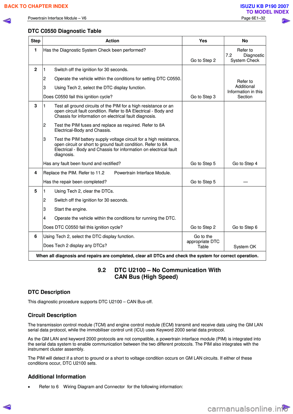
DTC C0550 Diagnostic Table
Step Action Yes No
1
Has the Diagnostic System Check been performed?
Go to Step 2 Refer to
7.2 Diagnostic System Check
2 1 Switch off the ignition for 30 seconds.
2 Operate the vehicle within the conditions for setting DTC C0550.
3 Using Tech 2, select the DTC display function.
Does C0550 fail this ignition cycle? Go to Step 3 Refer to
Additional
Information in this Section
3 1 Test all ground circuits of the PIM for a high resistance or an
open circuit fault condition. Refer to 8A Electrical - Body and
Chassis for information on electrical fault diagnosis.
2 Test the PIM fuses and replace as required. Refer to 8A Electrical-Body and Chassis.
3 Test the PIM battery supply voltage circuit for a high resistance, open circuit or short to ground fault condition. Refer to 8A
Electrical - Body and Chassis for information on electrical fault
diagnosis.
Has any fault been found and rectified? Go to Step 5 Go to Step 4
4 Replace the PIM. Refer to 11.2 Powertrain Interface Module.
Has the repair been completed? Go to Step 5 —
5 1 Using Tech 2, clear the DTCs.
2 Switch off the ignition for 30 seconds.
3 Start the engine.
4 Operate the vehicle within the conditions for running the DTC.
Does DTC C0550 fail this ignition cycle? Go to Step 2 Go to Step 6
6 Using Tech 2, select the DTC display function.
Does Tech 2 display any DTCs? Go to the
appropriate DTC
Table System OK
When all diagnosis and repairs are completed, clear all DTCs and check the system for correct operation.
9.2 DTC U2100 – No Communication With CAN Bus (High Speed)
DTC Description
This diagnostic procedure supports DTC U2100 – CAN Bus-off.
Circuit Description
The transmission control module (TCM) and engine control module (ECM) transmit and receive data using the GM LAN
serial data protocol, while the immobiliser control unit (ICU) uses Keyword 2000 serial data protocol.
As the GM LAN and keyword 2000 protocols are not compatible, a powertrain interface module (PIM) is integrated into
the serial data system to enable communication between the two different protocols. The PIM also integrates with the
instrument cluster assembly.
The PIM will detect if a short to ground or a short to voltage condition occurs on GM LAN circuits. If either of these
conditions occur, DTC U2100 sets.
Additional Information
• Refer to 6 W iring Diagram and Connector for the following information:
BACK TO CHAPTER INDEX
TO MODEL INDEX
ISUZU KB P190 2007
Page 3731 of 6020
Powertrain Interface Module – V6 Page 6E1–70
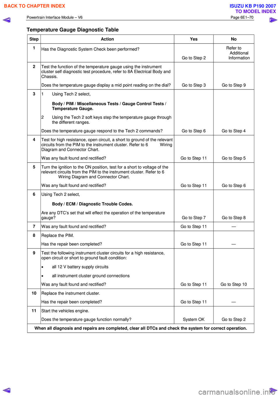
Temperature Gauge Diagnostic Table
Step Action Yes No
1
Has the Diagnostic System Check been performed?
Go to Step 2 Refer to
Additional
Information
2 Test the function of the temperature gauge using the instrument
cluster self diagnostic test procedure, refer to 8A Electrical Body and
Chassis.
Does the temperature gauge display a mid point reading on the dial? Go to Step 3 Go to Step 9
3
1 Using Tech 2 select,
Body / PIM / Miscellaneous Tests / Gauge Control Tests /
Temperature Gauge.
2 Using the Tech 2 soft keys step the temperature gauge through the different ranges.
Does the temperature gauge respond to the Tech 2 commands? Go to Step 6 Go to Step 4
4 Test for high resistance, open circuit, a short to ground of the relevant
circuits from the PIM to the instrument cluster. Refer to 6 W iring
Diagram and Connector Chart.
W as any fault found and rectified? Go to Step 11 Go to Step 5
5 Turn the ignition to the ON position, test for a short to voltage of the
relevant circuits from the PIM to the instrument cluster. Refer to 6
W iring Diagram and Connector Chart.
W as any fault found and rectified? Go to Step 11 Go to Step 6
6
Using Tech 2 select,
Body / ECM / Diagnostic Trouble Codes.
Are any DTC’s set that will effect the operation of the temperature
gauge? Go to Step 7 Go to Step 8
7 W as any fault found and rectified? Go to Step 11 —
8 Replace the PIM.
Has the repair been completed? Go to Step 11 —
9 Test the following instrument cluster circuits for a high resistance,
open circuit or short to ground fault condition:
• all 12 V battery supply circuits
• all instrument cluster ground connections
W as any fault found and rectified? Go to Step 11 Go to Step 10
10 Replace the instrument cluster.
Has the repair been completed? Go to Step 11 —
11 Start the vehicles engine.
Does the temperature gauge function normally? System OK Go to Step 2
When all diagnosis and repairs are completed, clear all DTCs and check the system for correct operation.
BACK TO CHAPTER INDEX
TO MODEL INDEX
ISUZU KB P190 2007
Page 3744 of 6020
Powertrain Interface Module – V6 Page 6E1–83
13.5 Security
F0: Immobiliser Link To ECM/PIM
Should the ECM, PIM or ICU be replaced, the modules must be security linked to each other. If this linking
procedure is not performed, the vehicle will not crank nor run. For additional information relating to Tech 2
and the linking procedure, refer to 11A – Immobiliser.
NOTE
After an ECU reset, the ignition switch must be
turned Off for at least 10 seconds and then
turned On for at least one minute, before
attempting communication between Tech 2 and
the ECU.
Preconditions: TIS approval (TIS 2000 Security Access) must be obtained, the four digit security number
entered into Tech 2 and the theft deterrent system disarmed. Then the ignition must be turned ‘On’, using a
programmed remote coded key.
F1: Reset PIM
This function erases the security link between the Engine Control Module (ECM) and the Powertrain Interface Modules (PIM). If this procedure is performed, the engine will not crank nor run. A ICU Link to ECM/PIM
procedure will need to be performed. For additional information relating to the ICU Link to ECM/PIM
procedure, refer to 11A – Immobiliser.
NOTE
After an ECU reset, the ignition switch must be
turned Off for at least 10 seconds and then
turned On for at least one minute, before
attempting communication between Tech 2 and
the ECU.
Preconditions: The four digit security code must be entered into Tech 2 and the ignition switched ‘On’ with a
programmed remote coded key.
F2: Security Information
The security code is required when performing certain PIM, ICU and ECM programming functions. W hen Tech 2 requests the security code to be entered, and an incorrect code is entered, the PIM will go into a
security wait time stage. This wait time stage will prevent any further attempts to enter the security code until
the wait time has elapsed.
Should a second incorrect security code be entered after the initial wait time has elapsed, the PIM will go into a second wait time stage. The wait time will increase each time an incorrect code is entered. W hen the
correct code is entered the wait time will reset back to its original value of 10 seconds.
NOTE
The ignition switch must be in the ON position
with the battery connected during the wait time
period.
The wait time stages are as follows: • Stage 1 = 10 seconds.
• Stage 2 = 10 seconds.
• Stage 3 = 10 minutes.
• Stage 4 = 20 minutes.
• Stage 5 = 40 minutes.
• Stage 5 = 80 minutes.
BACK TO CHAPTER INDEX
TO MODEL INDEX
ISUZU KB P190 2007
Page 3996 of 6020
7A2-30 TRANSMISSION CONTROL SYSTEM (AW30–40LE)
Service Programming System (SPS)
The procedure to program the control unit by using the
Service Programming System (SPS) software
contained in TIS2000 is explained below.
NOTE: • Should Tech2 display “SPS Procedure was not
successful”, engine will not start, but no DTCs are
present, low battery voltage or poor electrical
connections should be the primary suspects.
Perform the SPS procedure again after rectifying
the fault/s.
IMPORTANT:
Perform the following checks before attempting to
program the control unit:
•
••
•
The Tech2 PCMCIA card is programmed with
the latest software release.
•
••
•
The latest release of TIS2000 is loaded on the
PC.
•
••
•
The vehicle battery is fully charged.
•
••
•
The control unit to be programmed is
connected to the vehicle.
1. Preparations of TIS 2000
1. Connect Tech 2 to P/C.
2. Check to see if Hardware Key is plugged into Port.
3. Activate TIS 2000 by P/C.
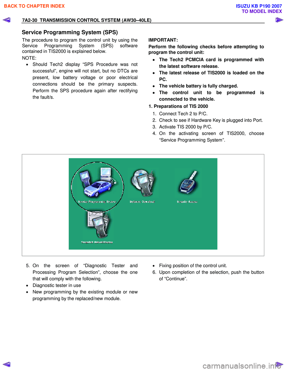
4. On the activating screen of TIS2000, choose
“Service Programming System”.
5. On the screen of “Diagnostic Tester and
Processing Program Selection”, choose the one
that will comply with the following.
• Diagnostic tester in use
• New programming by the existing module or ne
w
programming by the replaced/new module.
• Fixing position of the control unit.
6. Upon completion of the selection, push the button
of “Continue”.
BACK TO CHAPTER INDEX
TO MODEL INDEX
ISUZU KB P190 2007
Page 4000 of 6020
7A2-34 TRANSMISSION CONTROL SYSTEM (AW30–40LE)
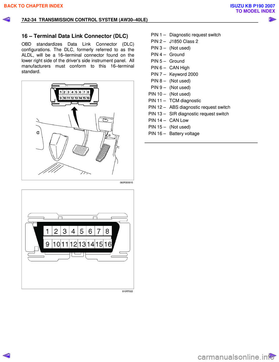
16 – Terminal Data Link Connector (DLC)
OBD standardizes Data Link Connector (DLC)
configurations. The DLC, formerly referred to as the
ALDL, will be a 16–terminal connector found on the
lower right side of the driver's side instrument panel. All
manufacturers must conform to this 16–terminal
standard.
060R300015
810RT022
PIN 1 – Diagnostic request switch
PIN 2 – J1850 Class 2
PIN 3 – (Not used)
PIN 4 – Ground
PIN 5 – Ground
PIN 6 – CAN High
PIN 7 – Keyword 2000
PIN 8 – (Not used)
PIN 9 – (Not used)
PIN 10 – (Not used)
PIN 11 – TCM diagnostic
PIN 12 – ABS diagnostic request switch
PIN 13 – SIR diagnostic request switch
PIN 14 – CAN Low
PIN 15 – (Not used)
PIN 16 – Battery voltage
BACK TO CHAPTER INDEX
TO MODEL INDEX
ISUZU KB P190 2007
Page 4007 of 6020
TRANSMISSION CONTROL SYSTEM (AW30–40LE) 7A2-41
• All of the following conditions are met.
- Device Control is not operating
- Disable Normal Communication Service is receiving enable
- DTC Clear is not operating
Condition For Setting The DTC
W hen the TCM detects following conditions at 20 times
continuously.
• Ignition voltage is less than 9 volts for 1 second o
r
more continuously. (DTC P0562)
• Ignition voltage is more than 18 volts for 1 second o
r
more continuously. (DTC P0563)
Action Taken When The DTC Sets
• DTC stored.
Conditions For Clearing The DTC
• The DTC can be cleared from the TCM history by
using a scan tool.
• The DTC will be cleared from history when the
vehicle has achieved 40 warm-up cycles without a
failure reported.
•
After more than 1 second has elapsed after the
ignition key has been turned “ON”, short between
No.11 and No.4 (ground) of DLC (Data Link
Connector). Then, after 1 second, but within 6
seconds, discontinue shorting.
Diagnostic Aids
•
Inspect the wiring for poor electrical connection at the
TCM. Look for possible bent, backed out, deformed
or damaged terminals. Check for weak terminal
tension as well. Also check for a chafed wire that
could short to bare metal or other wiring.
Inspect for a broken wire inside the insulation.
• W hen diagnosing for a possible intermittent short o
r
open condition, move the wiring harness while
observing test equipment for a change.
Circuit/System Testing DTC P0562 or P0563
Step Action Value(s) YES NO
1
W as the On-Board Diagnostic (OBD) System Check
performed? — Go to
Step 2 Go to OBD
System Check
2 Using the 5-8840-0285-0 DMM, measure the battery voltage at the battery.
Is the battery voltage greater than the specified value? 11.5 V Go to
Step 3 Charge battery,
then go to Step 3
3 1. Install a scan tool.
2. Select “Ignition Volts” on a scan tool.
3. Start the engine and raise the engine speed to the specified value.
4. Load the electrical system by turning on the headlights, high blower, etc.
Is the ignition voltage approximately equal to the
specified value? More than
1000 rpm
9.0-18.0 V Go to
Step 4 Go to
Starting/
Charging
BACK TO CHAPTER INDEX
TO MODEL INDEX
ISUZU KB P190 2007