2007 ISUZU KB P190 key battery
[x] Cancel search: key batteryPage 4301 of 6020
TRANSMISSION CONTROL SYSTEM (JR405E) 7A2-17
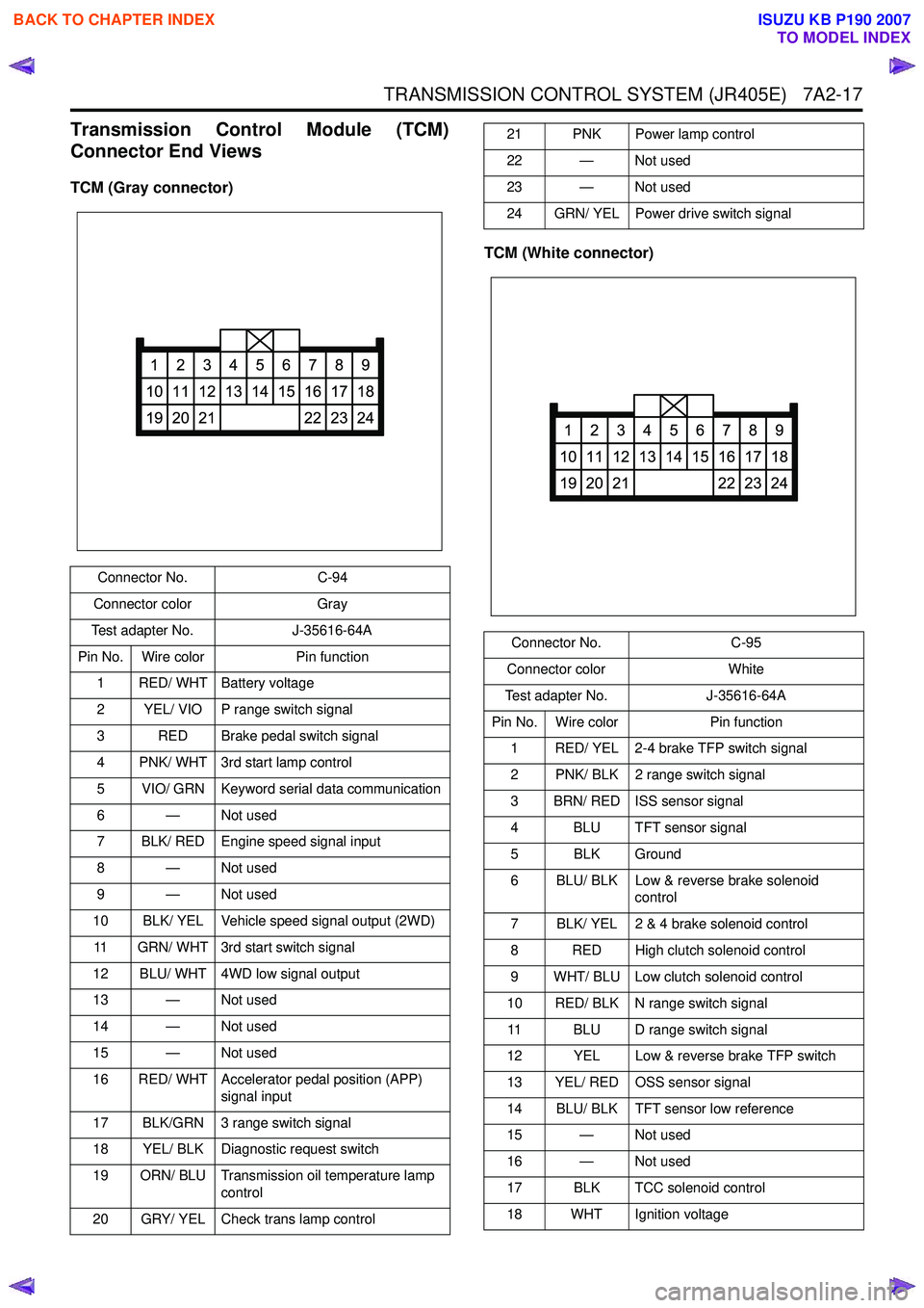
Transmission Control Module (TCM)
Connector End Views
TCM (Gray connector)
TCM (White connector)
Connector No.C-94
Connector color Gray
Test adapter No. J-35616-64A
Pin No. Wire color Pin function
1 RED/ WHT Battery voltage
2 YEL/ VIO P range switch signal
3 RED Brake pedal switch signal
4 PNK/ WHT 3rd start lamp control
5 VIO/ GRN Keyword serial data communication
6 — Not used
7 BLK/ RED Engine speed signal input
8 — Not used
9 — Not used
10 BLK/ YEL Vehicle speed signal output (2WD)
11 GRN/ WHT 3rd start switch signal
12 BLU/ WHT 4WD low signal output
13 — Not used
14 — Not used
15 — Not used
16 RED/ WHT Accelerator pedal position (APP) signal input
17 BLK/GRN 3 range switch signal
18 YEL/ BLK Diagnostic request switch
19 ORN/ BLU Transmission oil temperature lamp control
20 GRY/ YEL Check trans lamp control
1
10
19
2
11
20
3
12
21
4
13
5
14
6
15
7
16
22
8
17
23
9
18
24
21 PNK Power lamp control
22 — Not used
23 — Not used
24 GRN/ YEL Power drive switch signal
Connector No. C-95
Connector color White
Test adapter No. J-35616-64A
Pin No. Wire color Pin function
1 RED/ YEL 2-4 brake TFP switch signal
2 PNK/ BLK 2 range switch signal
3 BRN/ RED ISS sensor signal
4 BLU TFT sensor signal
5 BLK Ground
6 BLU/ BLK Low & reverse brake solenoid control
7 BLK/ YEL 2 & 4 brake solenoid control
8 RED High clutch solenoid control
9 WHT/ BLU Low clutch solenoid control
10 RED/ BLK N range switch signal 11 BLU D range switch signal
12 YEL Low & reverse brake TFP switch
13 YEL/ RED OSS sensor signal
14 BLU/ BLK TFT sensor low reference
15 — Not used
16 — Not used
17 BLK TCC solenoid control
18 WHT Ignition voltage
1
10
19
2
11
20
3
12
21
4
13
5
14
6
15
7
16
22
8
17
23
9
18
24
BACK TO CHAPTER INDEX
TO MODEL INDEX
ISUZU KB P190 2007
Page 4302 of 6020
7A2-18 TRANSMISSION CONTROL SYSTEM (JR405E)
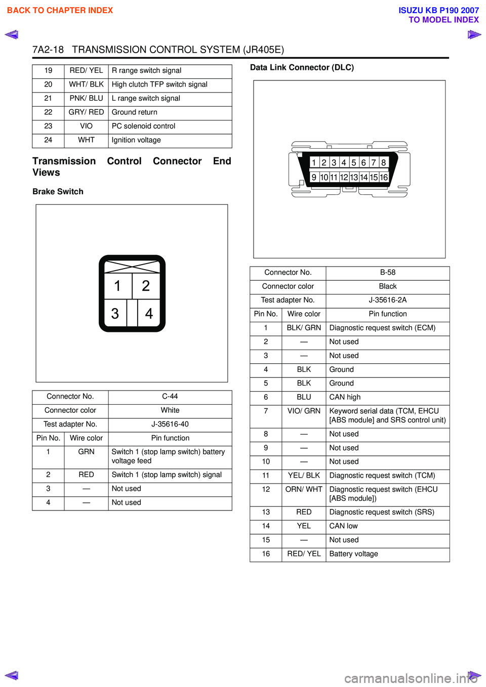
Transmission Control Connector End
Views
Brake Switch Data Link Connector (DLC)
19 RED/ YEL R range switch signal
20 WHT/ BLK High clutch TFP switch signal
21 PNK/ BLU L range switch signal
22 GRY/ RED Ground return
23 VIO PC solenoid control
24 WHT Ignition voltage
Connector No. C-44
Connector color White
Test adapter No. J-35616-40
Pin No. Wire color Pin function
1 GRN Switch 1 (stop lamp switch) battery voltage feed
2 RED Switch 1 (stop lamp switch) signal
3—Not used
4—Not used
21
34
Connector No. B-58
Connector color Black
Test adapter No. J-35616-2A
Pin No. Wire color Pin function
1 BLK/ GRN Diagnostic request switch (ECM)
2 — Not used
3 — Not used
4 BLK Ground
5 BLK Ground
6 BLU CAN high
7 VIO/ GRN Keyword serial data (TCM, EHCU [ABS module] and SRS control unit)
8 — Not used
9 — Not used
10 — Not used
11 YEL/ BLK Diagnostic request switch (TCM)
12 ORN/ WHT Diagnostic request switch (EHCU [ABS module])
13 RED Diagnostic request switch (SRS)
14 YEL CAN low
15 — Not used
16 RED/ YEL Battery voltage
87654321
16151413121110
9
BACK TO CHAPTER INDEX
TO MODEL INDEX
ISUZU KB P190 2007
Page 4306 of 6020
7A2-22 TRANSMISSION CONTROL SYSTEM (JR405E)
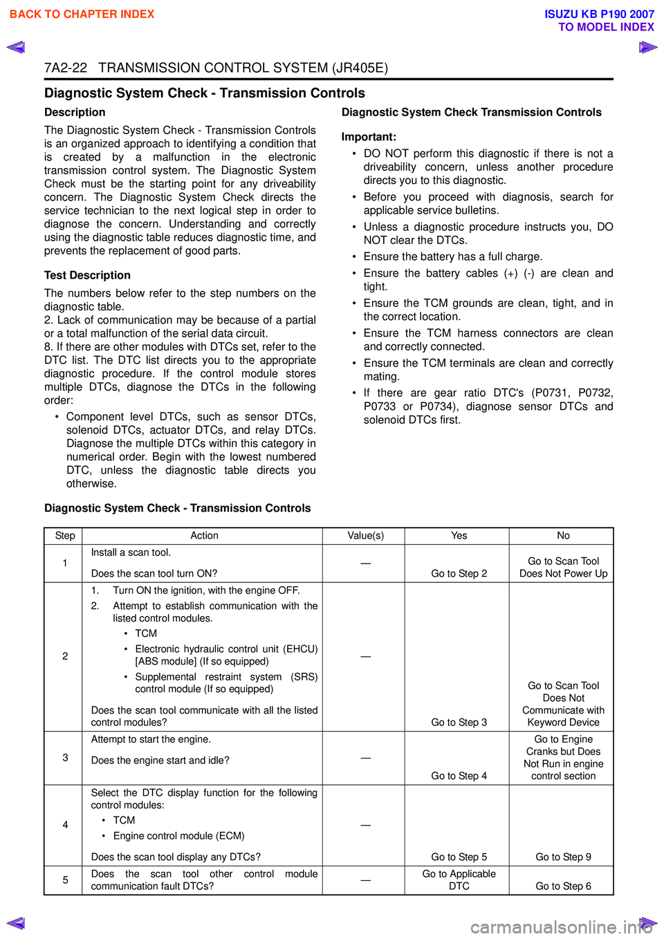
Diagnostic System Check - Transmission Controls
Description
The Diagnostic System Check - Transmission Controls
is an organized approach to identifying a condition that
is created by a malfunction in the electronic
transmission control system. The Diagnostic System
Check must be the starting point for any driveability
concern. The Diagnostic System Check directs the
service technician to the next logical step in order to
diagnose the concern. Understanding and correctly
using the diagnostic table reduces diagnostic time, and
prevents the replacement of good parts.
Test Description
The numbers below refer to the step numbers on the
diagnostic table.
2. Lack of communication may be because of a partial
or a total malfunction of the serial data circuit.
8. If there are other modules with DTCs set, refer to the
DTC list. The DTC list directs you to the appropriate
diagnostic procedure. If the control module stores
multiple DTCs, diagnose the DTCs in the following
order:
• Component level DTCs, such as sensor DTCs, solenoid DTCs, actuator DTCs, and relay DTCs.
Diagnose the multiple DTCs within this category in
numerical order. Begin with the lowest numbered
DTC, unless the diagnostic table directs you
otherwise. Diagnostic System Check Transmission Controls
Important: • DO NOT perform this diagnostic if there is not a driveability concern, unless another procedure
directs you to this diagnostic.
• Before you proceed with diagnosis, search for applicable service bulletins.
• Unless a diagnostic procedure instructs you, DO NOT clear the DTCs.
• Ensure the battery has a full charge.
• Ensure the battery cables (+) (-) are clean and tight.
• Ensure the TCM grounds are clean, tight, and in the correct location.
• Ensure the TCM harness connectors are clean and correctly connected.
• Ensure the TCM terminals are clean and correctly mating.
• If there are gear ratio DTC's (P0731, P0732, P0733 or P0734), diagnose sensor DTCs and
solenoid DTCs first.
Diagnostic System Check - Transmission Controls
Step Action Value(s)Yes No
1 Install a scan tool.
Does the scan tool turn ON? —
Go to Step 2 Go to Scan Tool
Does Not Power Up
2 1. Turn ON the ignition, with the engine OFF.
2. Attempt to establish communication with the listed control modules.
•TCM
• Electronic hydraulic control unit (EHCU) [ABS module] (If so equipped)
• Supplemental restraint system (SRS) control module (If so equipped)
Does the scan tool communicate with all the listed
control modules? —
Go to Step 3 Go to Scan Tool
Does Not
Communicate with Keyword Device
3 Attempt to start the engine.
Does the engine start and idle? —
Go to Step 4 Go to Engine
Cranks but Does
Not Run in engine control section
4 Select the DTC display function for the following
control modules:
•TCM
• Engine control module (ECM)
Does the scan tool display any DTCs? —
Go to Step 5 Go to Step 9
5 Does the scan tool other control module
communication fault DTCs? —Go to Applicable
DTC Go to Step 6
BACK TO CHAPTER INDEX
TO MODEL INDEX
ISUZU KB P190 2007
Page 4418 of 6020
7A2-134 TRANSMISSION CONTROL SYSTEM (JR405E)
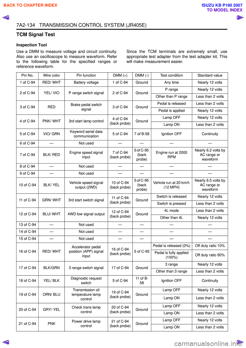
TCM Signal Test
Inspection Tool
Use a DMM to measure voltage and circuit continuity.
Also use an oscilloscope to measure waveform. Refer
to the following table for the specified ranges or
reference waveform. Since the TCM terminals are extremely small, use
appropriate test adapter from the test adapter kit. This
will make measurement easier.
Pin No. Wire color Pin function DMM (+) DMM (-) Test condition Standard value
1 of C-94 RED/ WHT Battery voltage 1 of C-94 Ground Any time Nearly 12 volts
2 of C-94 YEL/ VIO P range switch signal 2 of C-94 Ground P range
Nearly 12 volts
Other than P range Less than 2 volts
3 of C-94 RED Brake pedal switch
signal 3 of C-94 Ground Pedal is released Less than 2 volts
Pedal is applied Nearly 12 volts
4 of C-94 PNK/ WHT 3rd start lamp control 4 of C-94
(back probe) Ground Lamp OFF Nearly 12 volts
Lamp ON Less than 2 volts
5 of C-94 VIO/ GRN Keyword serial data
communication 5 of C-94 7 of B-58 Ignition OFF
Continuity
6 of C-94 — Not used— — ——
7 of C-94 BLK/ RED Engine speed signal
input 7 of C-94
(back probe) 5 of C-95
(back
probe) Engine run at 2000
RPM Nearly 6.2 volts by
AC range or
waveform
8 of C-94 — Not used— — ——
9 of C-94 — Not used— — ——
10 of C-94 BLK/ YEL Vehicle speed signal
output (2WD) 10 of C-94
(back probe) 5 of C-95
(back
probe) Vehicle run at 20 km/h
(12 MPH) Nearly 6.5 volts by
AC range or waveform
11 of C-94 GRN/ WHT 3rd start switch signal 11 of C-94
(back probe) GroundSwitch is released Nearly 12 volts
Switch is pressed Less than 2 volts
12 of C-94 BLU/ WHT 4WD low signal output 12 of C-94
(back probe) Ground 4L mode Less than 2 volts
Other than 4L Nearly 12 volts
13 of C-94 — Not used— — ——
14 of C-94 — Not used— — ——
15 of C-94 — Not used— — ——
16 of C-94 RED/ WHT Accelerator pedal
position (APP) signal
input 16 of C-94
(back probe) 5 of C-95Pedal is released (0%) Off duty ratio 10%
Pedal is fully applied (100%) Off duty ratio 90%
17 of C-94 BLK/GRN 3 range switch signal 17 of C-94 Ground 3 range
Nearly 12 volts
Other than 3 range Less than 2 volts
18 of C-94 YEL/ BLK Diagnostic request
switch 5 of C-9411 o f B -
58 Ignition OFF
Continuity
19 of C-94 ORN/ BLU Transmission oil
temperature lamp control 19 of C-94
(back probe) Ground Lamp OFF Nearly 12 volts
Lamp ON Less than 2 volts
20 of C-94 GRY/ YEL Check trans lamp
control 20 of C-94
(back probe) Ground Lamp OFF Nearly 12 volts
Lamp ON Less than 2 volts
21 of C-94 PNK Power drive lamp
control 21 of C-94
(back probe) Ground Lamp OFF Nearly 12 volts
Lamp ON Less than 2 volts
BACK TO CHAPTER INDEX
TO MODEL INDEX
ISUZU KB P190 2007
Page 4423 of 6020
TRANSMISSION CONTROL SYSTEM (JR405E) 7A2-139
Repair Instructions
Transmission Controls Module (TCM) Replacement
Description
The following A - C steps provide an overview
procedure to replace and reprogram a TCM. Each A -C
steps is explained further in this section.
A. Replace the old TCM with the new TCM.
B. Program the latest software and calibrations into the
new TCM using the Service Programming System
(SPS) if released. If not released, do not perform this
and skip to Step C.
C. Program the vehicle identification number (VIN) into
the TCM.
A. Removal and Installation
Removal Procedure 1. Disconnect the negative battery cable.
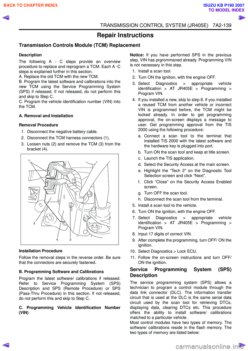
2. Disconnect the TCM harness connectors (1).
3. Loosen nuts (2) and remove the TCM (3) from the bracket (4).
Installation Procedure
Follow the removal steps in the reverse order. Be sure
that the connectors are securely fastened.
B. Programming Software and Calibrations
Program the latest software/ calibrations if released.
Refer to Service Programming System (SPS)
Description and SPS (Remote Procedure) or SPS
(Pass-Thru Procedure) in this section. If not released,
do not perform this and skip to Step C.
C. Programming Vehicle Identification Number
(VIN) Notice:
If you have performed SPS in the previous
step, VIN has prgrommaned already. Programming VIN
is not necessary in this step.
1. Install a scan tool.
2. Turn ON the ignition, with the engine OFF.
3. Select Diagnostics > appropriate vehicle identification > AT JR405E > Programming >
Program VIN.
4. If you installed a new, skip to step 8. If you installed a reused TCM from another vehicle or incorrect
VIN is programmed before, the TCM might be
locked already. In order to get programming
approval, the on-screen displays a message to
user. Get programming approval from the TIS
2000 using the following procedure:
a. Connect a scan tool to the terminal that installed TIS 2000 with the latest software and
the hardware key is plugged into port.
b. Turn ON the scan tool and keep at title screen.
c. Launch the TIS application.
d. Select the Security Access at the main screen.
e. Highlight the “Tech 2" on the Diagnostic Tool Selection screen and click “Next”.
f. Click “Close” on the Security Access Enabled screen.
g. Turn OFF the scan tool.
h. Disconnect the scan tool from the terminal.
5. Install a scan tool to the vehicle.
6. Turn ON the ignition, with the engine OFF.
7. Select Diagnostics > appropriate vehicle identification > AT JR405E > Programming >
Program VIN.
8. Input 17 digits of correct VIN.
9. After complete the programming, turn OFF/ ON the ignition.
10. Select Diagnostics > Lock ECU.
11. Follow the on-screen instructions and turn OFF/ ON the ignition.
Service Programming System (SPS)
Description
The service programming system (SPS) allows a
technician to program a control module through the
data link connector (DLC). The information transfer
circuit that is used at the DLC is the same serial data
circuit used by the scan tool for retrieving DTCs,
displaying data, clearing DTCs etc. This procedure
offers the ability to install software/ calibrations
matched to a particular vehicle.
Most control modules have two types of memory. The
software/ calibrations reside in the flash memory. The
two types of memory are listed below:
1
3 42
BACK TO CHAPTER INDEX
TO MODEL INDEX
ISUZU KB P190 2007
Page 4424 of 6020
7A2-140 TRANSMISSION CONTROL SYSTEM (JR405E)
• Electrically Erasable Programmable Read OnlyMemory (EEPROM)
This type of memory allows selected portions of
memory to be programmed while other portions
remain unchanged.
Certain learned values reside in the EEPROM,
such as:
- The vehicle identification number (VIN)
- The software/ calibrations identification numbers
- The control module security information
• Flash Read Only Memory-Flash Memory
Flash memory has increased memory storage capacity.
During programming, all information within this type of
memory is erased, and then replaced with entirely new
information.
Service Programming Methods
The two methods of programming a TCM are listed
below:
• Remote Programming
• Pass Thru Programming
For information on programming a TCM using one of
the methods listed above, refer to Service
Programming System (SPS) (Remote Procedure) or
Service Programming System (SPS) (Pass-Thru
Procedure).
Before Programming a Control Module
Important: DO NOT program an existing TCM with the
identical software/ calibration package. This procedure
is not a short cut to correct the driveability condition.
This is an ineffective repair. An TCM should only be
programmed when the following occurs:
• When a service procedure instructs you to replace the TCM.
• An updated software/ calibrations is released.
Ensure that the following conditions are met before
programming a TCM:
• The scan tool PCMCIA card is programmed with the latest software.
• The TIS 2000 is installed with the latest software.
• The hardware key is plugged into the computer port.
• Vehicle system voltage:
- There are no charging system concerns. Allcharging system concerns must be repaired
before programming the TCM.
- The battery voltage is greater than 12 volts but less than 16 volts. The battery must be fully
charged before programming the TCM.
- A battery charger is NOT connected to the vehicles battery. Incorrect system voltage or
voltage fluctuations from a battery charger may
cause programming failure or TCM damage. - Turn OFF or disable any system that may put a
load on the vehicles battery. Turn OFF or
disable systems such as:
◊ Heating, ventilation, and air conditioning
(HVAC) systems
◊ Headlights
◊ Room lights
◊ Accessory equipment
• The ignition switch is in the proper position. The scan tool prompts you to turn ON the ignition, with
the engine OFF. DO NOT change the position of
the ignition switch during the programming
procedure unless instructed to do so.
• All tool connections are secure:
- The RS-232 cable
- The connection at the DLC
- The voltage supply circuits
• DO NOT disturb the tool harnesses while programming. If an interruption occurs during the
programming procedure, programming failure or
TCM damage may occur.
• If you are performing the Pass-Thru programming procedure using a notebook computer without the
power cord, ensure that the internal battery is fully
charged.
Service Programming System (SPS)
(Remote Procedure)
Notice: Some module will not accept SPS remote
procedure using 10MB PCMCIA card. In such case,
use 32MB PCMCIA card or SPS pass-thru procedure.
The Remote SPS method is a three-step process that
involves the following procedures:
1. Connecting the scan tool to the vehicle and obtaining the information from the TCM.
2. Connecting the scan tool to the terminal and downloading a new calibration file from the
terminal into the scan tool memory.
3. Reconnecting the scan tool to the vehicle and uploading the new calibration file into the TCM.
Performing the Remote Procedure 1. Connect a scan tool to the vehicle and obtain the TCM information using the following procedure:
Notice: Ensure the TCM is installed in the vehicle and
the battery is fully charged before programming.
a. Install a scan tool.
b. Turn ON the ignition, with the engine OFF.
c. Select Service Programming System (SPS) > Request Info.
BACK TO CHAPTER INDEX
TO MODEL INDEX
ISUZU KB P190 2007
Page 5048 of 6020
8A-110 ELECTRICAL-BODY AND CHASSIS
REMOVAL AND INSTALLATION
This illustration is based on RHD model
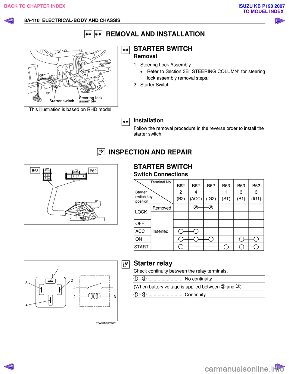
STARTER SWITCH
Removal
1. Steering Lock Assembly • Refer to Section 3B" STEERING COLUMN" for steering
lock assembly removal steps.
2. Starter Switch
Installation
Follow the removal procedure in the reverse order to install the
starter switch.
INSPECTION AND REPAIR
B62 B63
STARTER SWITCH
Switch Connections
Terminal No.
Starter
switch key
position B62
2
(B2) B62
4
(ACC) B62
1
(IG2) B63
1
(ST) B63
3
(B1) B62
3
(IG1)
Removed
OFF
ACC Inserted
ON
START
LOCK
RTW 78ASH003001
Starter relay
Check continuity between the relay terminals.
1 - 4............................ No continuity
(W hen battery voltage is applied between 2 and 3)
1 - 4............................ Continuity
BACK TO CHAPTER INDEX TO MODEL INDEXISUZU KB P190 2007
Page 5307 of 6020
ELECTRICAL-BODY AND CHASSIS 8A-369
Low Fuel Indicator Light
1. Disconnect the fuel gauge unit wire connector.
2. Turn the key switch on. Check that the bulb lights.
If operation is not correct, remove and check the bulb or circuit.
or If check whether low fuel turns on fuel input (B-24) at the
time of open and key on.
∗ meter is check at low fuel
RTW 78ASH001501
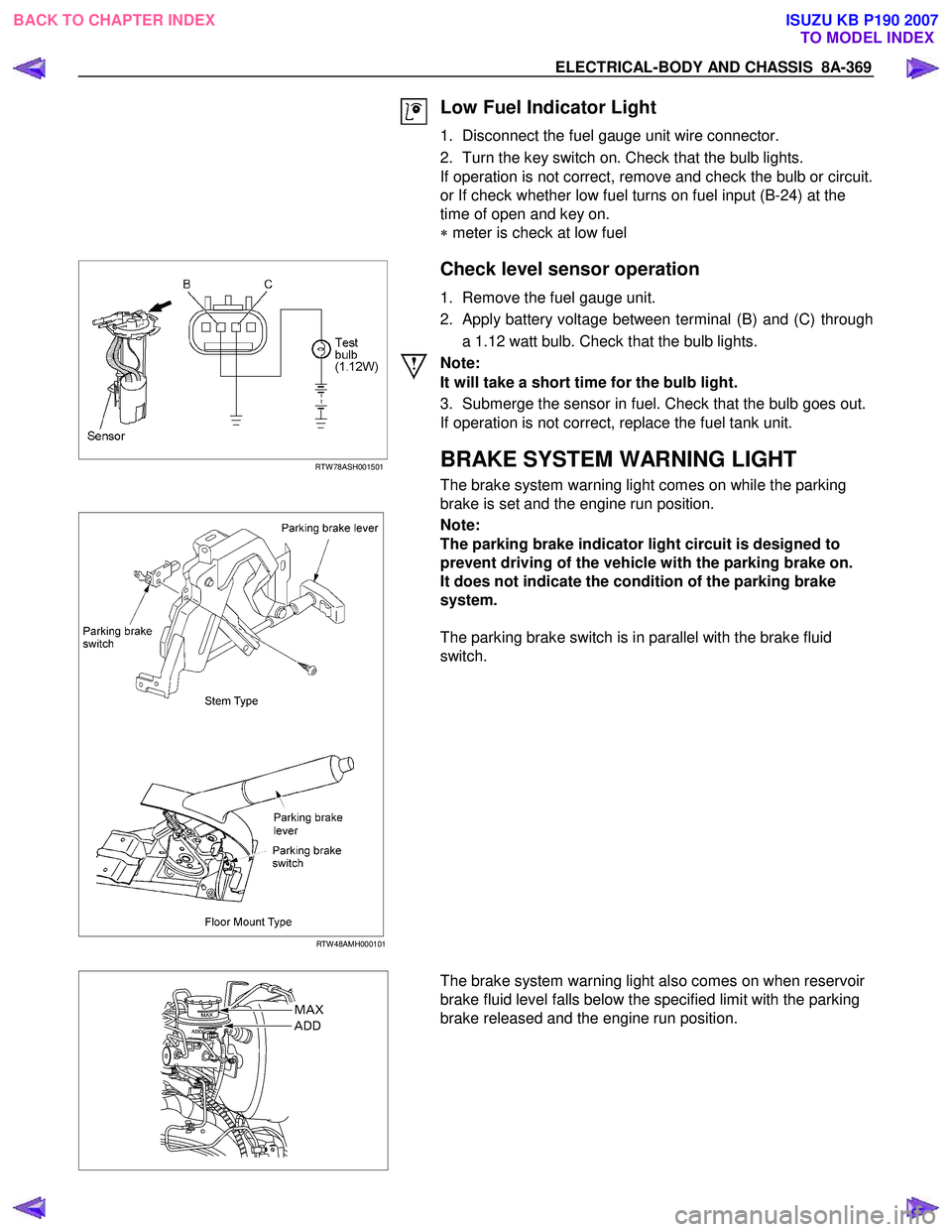
Check level sensor operation
1. Remove the fuel gauge unit.
2. Apply battery voltage between terminal (B) and (C) through a 1.12 watt bulb. Check that the bulb lights.
Note:
It will take a short time for the bulb light.
3. Submerge the sensor in fuel. Check that the bulb goes out.
If operation is not correct, replace the fuel tank unit.
BRAKE SYSTEM WARNING LIGHT
The brake system warning light comes on while the parking
brake is set and the engine run position.
RTW 48AMH000101
Note:
The parking brake indicator light circuit is designed to
prevent driving of the vehicle with the parking brake on.
It does not indicate the condition of the parking brake
system.
The parking brake switch is in parallel with the brake fluid
switch.
The brake system warning light also comes on when reservoir
brake fluid level falls below the specified limit with the parking
brake released and the engine run position.
BACK TO CHAPTER INDEX TO MODEL INDEXISUZU KB P190 2007