2007 ISUZU KB P190 key battery
[x] Cancel search: key batteryPage 1949 of 6020
6E-332 ENGINE CONTROL SYSTEM (4JK1/4JJ1)
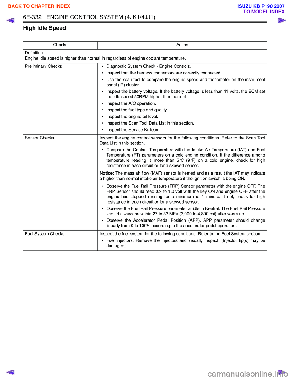
High Idle Speed
ChecksAction
Definition:
Engine idle speed is higher than normal in regardless of engine coolant temperature.
Preliminary Checks • Diagnostic System Check - Engine Controls.
• Inspect that the harness connectors are correctly connected.
• Use the scan tool to compare the engine speed and tachometer on the instrument panel (IP) cluster.
• Inspect the battery voltage. If the battery voltage is less than 11 volts, the ECM set the idle speed 50RPM higher than normal.
• Inspect the A/C operation.
• Inspect the fuel type and quality.
• Inspect the engine oil level.
• Inspect the Scan Tool Data List in this section.
• Inspect the Service Bulletin.
Sensor Checks Inspect the engine control sensors for the following conditions. Refer to the Scan Tool
Data List in this section.
• Compare the Coolant Temperature with the Intake Air Temperature (IAT) and Fuel Temperature (FT) parameters on a cold engine condition. If the difference among
temperature reading is more than 5 °C (9 °F) on a cold engine, check for high
resistance in each circuit or for a skewed sensor.
Notice: The mass air flow (MAF) sensor is heated and as a result the IAT may indicate
a higher than normal intake air temperature if the ignition switch is being ON.
• Observe the Fuel Rail Pressure (FRP) Sensor parameter with the engine OFF. The FRP Sensor should read 0.9 to 1.0 volt with the key ON and engine OFF after the
engine has stopped running for a minimum of 1 minute. If not, check for high
resistance in each circuit or for a skewed sensor.
• Observe the Fuel Rail Pressure parameter at idle in Neutral. The Fuel Rail Pressure should always be within 27 to 33 MPa (3,900 to 4,800 psi) after warm up.
• Observe the Accelerator Pedal Position (APP). APP parameter should change linearly from 0 to 100% according to the accelerator pedal operation.
Fuel System Checks Inspect the fuel system for the following conditions. Refer to the Fuel System section.
• Fuel injectors. Remove the injectors and visually inspect. (Injector tip(s) may be damaged)
BACK TO CHAPTER INDEX
TO MODEL INDEX
ISUZU KB P190 2007
Page 1967 of 6020
6E-350 ENGINE CONTROL SYSTEM (4JK1/4JJ1)
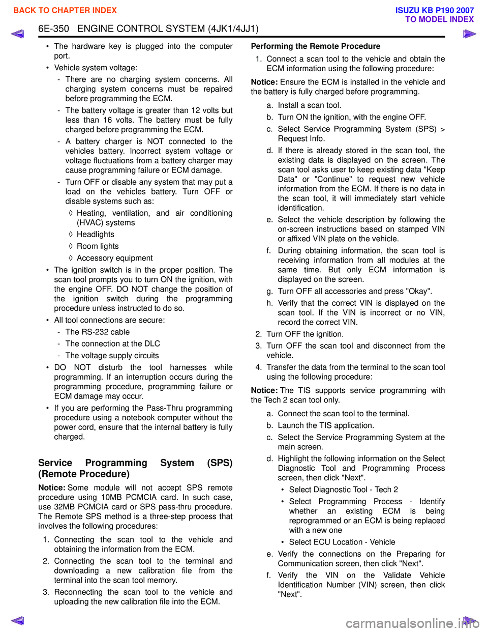
• The hardware key is plugged into the computerport.
• Vehicle system voltage: - There are no charging system concerns. Allcharging system concerns must be repaired
before programming the ECM.
- The battery voltage is greater than 12 volts but less than 16 volts. The battery must be fully
charged before programming the ECM.
- A battery charger is NOT connected to the vehicles battery. Incorrect system voltage or
voltage fluctuations from a battery charger may
cause programming failure or ECM damage.
- Turn OFF or disable any system that may put a load on the vehicles battery. Turn OFF or
disable systems such as:
◊ Heating, ventilation, and air conditioning
(HVAC) systems
◊ Headlights
◊ Room lights
◊ Accessory equipment
• The ignition switch is in the proper position. The scan tool prompts you to turn ON the ignition, with
the engine OFF. DO NOT change the position of
the ignition switch during the programming
procedure unless instructed to do so.
• All tool connections are secure: - The RS-232 cable
- The connection at the DLC
- The voltage supply circuits
• DO NOT disturb the tool harnesses while programming. If an interruption occurs during the
programming procedure, programming failure or
ECM damage may occur.
• If you are performing the Pass-Thru programming procedure using a notebook computer without the
power cord, ensure that the internal battery is fully
charged.
Service Programming System (SPS)
(Remote Procedure)
Notice: Some module will not accept SPS remote
procedure using 10MB PCMCIA card. In such case,
use 32MB PCMCIA card or SPS pass-thru procedure.
The Remote SPS method is a three-step process that
involves the following procedures:
1. Connecting the scan tool to the vehicle and obtaining the information from the ECM.
2. Connecting the scan tool to the terminal and downloading a new calibration file from the
terminal into the scan tool memory.
3. Reconnecting the scan tool to the vehicle and uploading the new calibration file into the ECM. Performing the Remote Procedure
1. Connect a scan tool to the vehicle and obtain the ECM information using the following procedure:
Notice: Ensure the ECM is installed in the vehicle and
the battery is fully charged before programming.
a. Install a scan tool.
b. Turn ON the ignition, with the engine OFF.
c. Select Service Programming System (SPS) > Request Info.
d. If there is already stored in the scan tool, the existing data is displayed on the screen. The
scan tool asks user to keep existing data "Keep
Data" or "Continue" to request new vehicle
information from the ECM. If there is no data in
the scan tool, it will immediately start vehicle
identification.
e. Select the vehicle description by following the on-screen instructions based on stamped VIN
or affixed VIN plate on the vehicle.
f. During obtaining information, the scan tool is receiving information from all modules at the
same time. But only ECM information is
displayed on the screen.
g. Turn OFF all accessories and press "Okay".
h. Verify that the correct VIN is displayed on the scan tool. If the VIN is incorrect or no VIN,
record the correct VIN.
2. Turn OFF the ignition.
3. Turn OFF the scan tool and disconnect from the vehicle.
4. Transfer the data from the terminal to the scan tool using the following procedure:
Notice: The TIS supports service programming with
the Tech 2 scan tool only.
a. Connect the scan tool to the terminal.
b. Launch the TIS application.
c. Select the Service Programming System at the main screen.
d. Highlight the following information on the Select Diagnostic Tool and Programming Process
screen, then click "Next".
• Select Diagnostic Tool - Tech 2
• Select Programming Process - Identify whether an existing ECM is being
reprogrammed or an ECM is being replaced
with a new one
• Select ECU Location - Vehicle
e. Verify the connections on the Preparing for Communication screen, then click "Next".
f. Verify the VIN on the Validate Vehicle Identification Number (VIN) screen, then click
"Next".
BACK TO CHAPTER INDEX
TO MODEL INDEX
ISUZU KB P190 2007
Page 2129 of 6020
ENGINE FUEL (C24SE) 6C-11
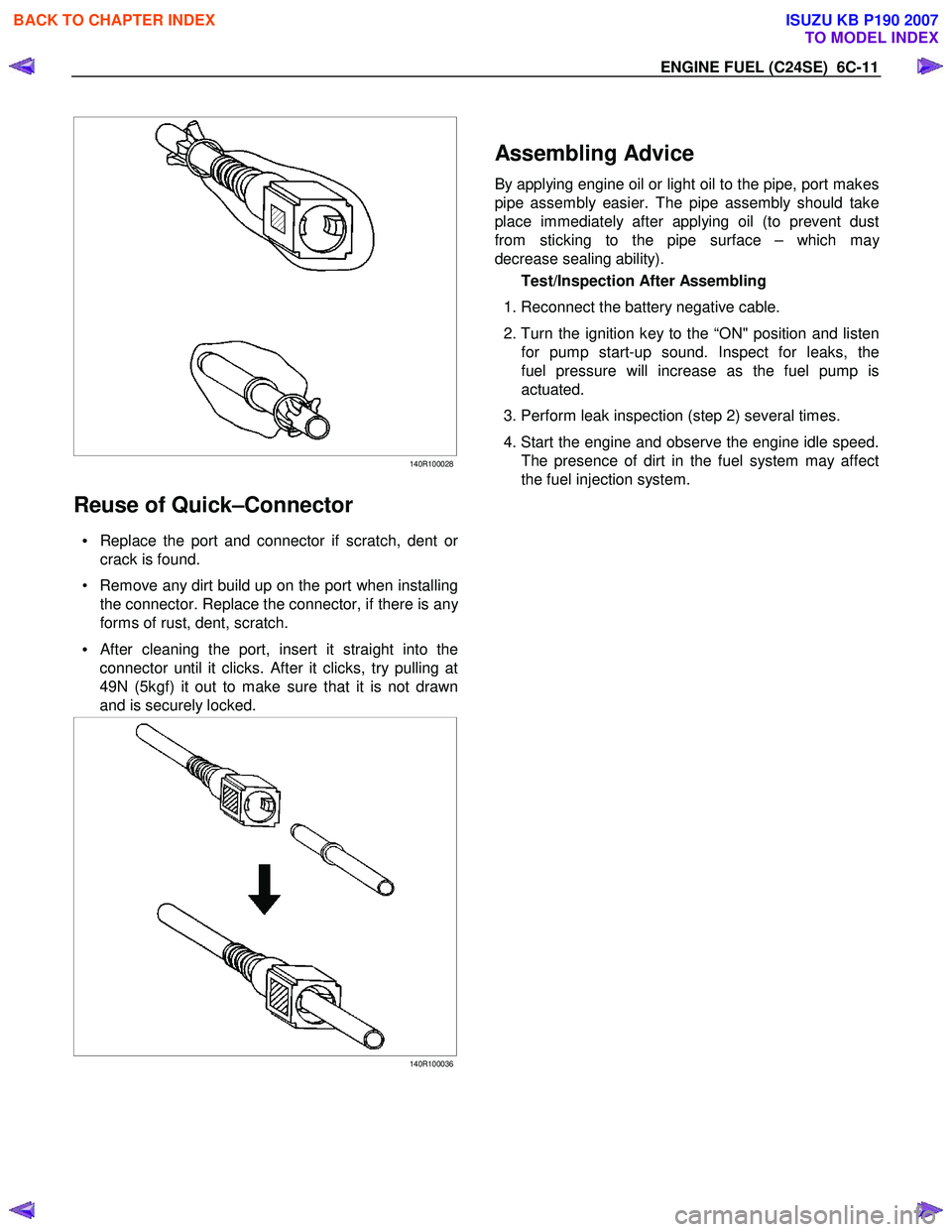
140R100028
Reuse of Quick–Connector
• Replace the port and connector if scratch, dent or
crack is found.
• Remove any dirt build up on the port when installing the connector. Replace the connector, if there is an
y
forms of rust, dent, scratch.
•
After cleaning the port, insert it straight into the
connector until it clicks. After it clicks, try pulling at
49N (5kgf) it out to make sure that it is not drawn
and is securely locked.
140R100036
Assembling Advice
By applying engine oil or light oil to the pipe, port makes
pipe assembly easier. The pipe assembly should take
place immediately after applying oil (to prevent dust
from sticking to the pipe surface – which ma
y
decrease sealing ability).
Test/Inspection After Assembling
1. Reconnect the battery negative cable.
2. Turn the ignition key to the “ON" position and listen
for pump start-up sound. Inspect for leaks, the
fuel pressure will increase as the fuel pump is
actuated.
3. Perform leak inspection (step 2) several times.
4. Start the engine and observe the engine idle speed.
The presence of dirt in the fuel system may affect
the fuel injection system.
BACK TO CHAPTER INDEX
TO MODEL INDEX
ISUZU KB P190 2007
Page 2214 of 6020
6E–44 ENGINE DRIVEABILITY AND EMISSIONS
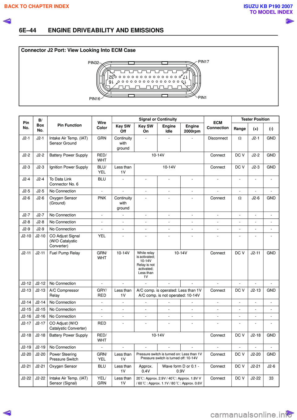
Connector J2 Port: View Looking Into ECM Case
1
17 16
32
PIN32
PIN1
PIN17
PIN16
Pin
No. B/
Box No. Pin Function
Wire
Color Signal or Continuity
ECM
Connection Tester Position
Key SW Off Key SW
On Engine
Idle Engine
2000rpm Range (+) (-)
J2-1 J2-1 Intake Air Temp. (IAT) Sensor Ground GRN Continuity
with
ground -
- - Disconnect ΩJ2-1 GND
J2-2 J2-2 Battery Power Supply RED/ WHT10-14V
Connect DC V J2-2 GND
J2-3 J2-3 Ignition Power Supply BLU/ YELLess than
1V 10-14V
Connect DC V J2-3 GND
J2-4 J2-4 To Data Link Connector No. 6 BLU -
-- - -- - -
J2-5 J2-5 No Connection -- - - - -- - -
J2-6 J2-6 Oxygen Sensor (Ground) PNK Continuity
with
ground -
- - Connect ΩJ2-6 GND
J2-7 J2-7 No Connection -- - - - -- - -
J2-8 J2-8 No Connection -- - - - -- - -
J2-9 J2-9 No Connection -- - - - -- - -
J2-10 J2-10 CO Adjust Signal (W/O Catalystic
Converter) YEL -
-- - -- - -
J2-11 J2-11 Fuel Pump Relay GRN/ WHT10-14V
While relay
is activated; 10-14V
Relay is not
activated;
Less than 1V10-14V Connect DC V J2-11 GND
J2-12 J2-12 No Connection -- - - - -- - -
J2-13 J2-13 A/C Compressor Relay GRY/
RED Less than
1V A/C comp. is operated: Less than 1V
A/C comp. is not operated: 10-14V Connect DC V J2-13 GND
J2-14 J2-14 No Connection -- - - - -- - -
J2-15 J2-15 No Connection -- - - - -- - -
J2-16 J2-16 No Connection -- - - - -- - -
J2-17 J2-17 CO Adjust (W/O Catalystic Converter) RED -
-- - -- - -
J2-18 J2-18 Battery Power Supply RED/ WHT10-14V
Connect DC V J2-18 GND
J2-19 J2-19 No Connection -- - - - -- - -
J2-20 J2-20 Power Steering Pressure Switch GRN/
YEL Less than
1V
Pressure switch is turned on: Less than 1VPressure switch is turned off: 10-14VConnect DC V J2-20 GND
J2-21 J2-21 Oxygen Sensor BLU Less than 1VApprox.
0.4V Wave form D or 0.1 -
0.9V Connect DC V J2-21 J2-6
J2-22 J2-22 Intake Air Temp. (IAT) Sensor (Signal) YEL/
GRN Less than
1V
20℃: Approx. 2.9V / 40 ℃: Approx. 1.8V V
/ 60 ℃: Approx. 1.1V / 80 ℃: Approx. 0.6VConnect DC V J2-22 33
BACK TO CHAPTER INDEX
TO MODEL INDEX
ISUZU KB P190 2007
Page 2219 of 6020

ENGINE DRIVEABILITY AND EMISSIONS 6E–49
Throttle Position Sensor (TPS)
The TPS is a potentiometer connected to throttle shaft
on the throttle body.
The engine control module (ECM) monitors the voltage
on the signal line and calculates throttle position. As the
throttle valve angle is changed when accelerator pedal
moved. The TPS signal also changed at a moved
throttle valve. As the throttle valve opens, the output
increases so that the output voltage should be high.
The throttle body has a throttle plate to control the
amount of the air delivered to the engine.
Engine coolant is directed through a coolant cavity in
the throttle body to warm the throttle valve and to
prevent icing.
Idle Air Control (IAC) Valve
The idle air control valve (IAC) valve is two directional
and gives 2-way control. With power supply to the coils
controlled steps by the engine control module (ECM),
the IAC valve's pintle is moved to adjust idle speed,
raising it for fast idle when cold or there is extra load
from the air conditioning or power steering.
By moving the pintle in (to decrease air flow) or out (to
increase air flow), a controlled amount of the air can
move around the throttle plate. If the engine speed is
too low, the engine control module (ECM) will retract the
IAC pintle, resulting in more air moving past the throttle
plate to increase the engine speed.
If the engine speed is too high, the engine control
module (ECM) will extend the IAC pintle, allowing less
air to move past the throttle plate, decreasing the
engine speed.
The IAC pintle valve moves in small step called counts.
During idle, the proper position of the IAC pintle is
calculated by the engine control module (ECM) based
on battery voltage, coolant temperature, engine load,
and engine speed.
If the engine speed drops below a specified value, and
the throttle plate is closed, the engine control module
(ECM) senses a near-stall condition. The engine control
module (ECM) will then calculate a new IAC pintle valve
position to prevent stalls.
If the IAC valve is disconnected and reconnected with
the engine running, the idle speed will be wrong. In this
case, the IAC must be reset. The IAC resets when the
key is cycled “On” then “Off”. When servicing the IAC, it
should only be disconnected or connected with the
ignition “Off”.
The position of the IAC pintle valve affects engine start-
up and the idle characteristic of the vehicle.
If the IAC pintle is fully open, too much air will be
allowed into the manifold. This results in high idle
speed, along with possible hard starting and lean air/
fuel ratio.
(1) Throttle Position Sensor
(2) Idle Air Control (IAC) Valve
1
2
C harac teris t ic of TPS -R ef erenc e-
0
0.5
1
1.5 2
2.5
3
3.5 4
4.5 5
0 10 2030 405060 7080 90100 Throt t le Angle (% ) (Tec h2 R eading)
Output Voltage (V)
StepCoilAB CDCoil A H igh
(ECM J1-28) On On
Coil A Low
(ECM J1-30) On On
Coil B H igh
(ECM J1-13) On On
Coil B Low
(ECM J1-29) On On
(IAC Valve Close Direction)
(IAC Valve Open Direction)
BACK TO CHAPTER INDEX
TO MODEL INDEX
ISUZU KB P190 2007
Page 2254 of 6020
6E–84 ENGINE DRIVEABILITY AND EMISSIONS
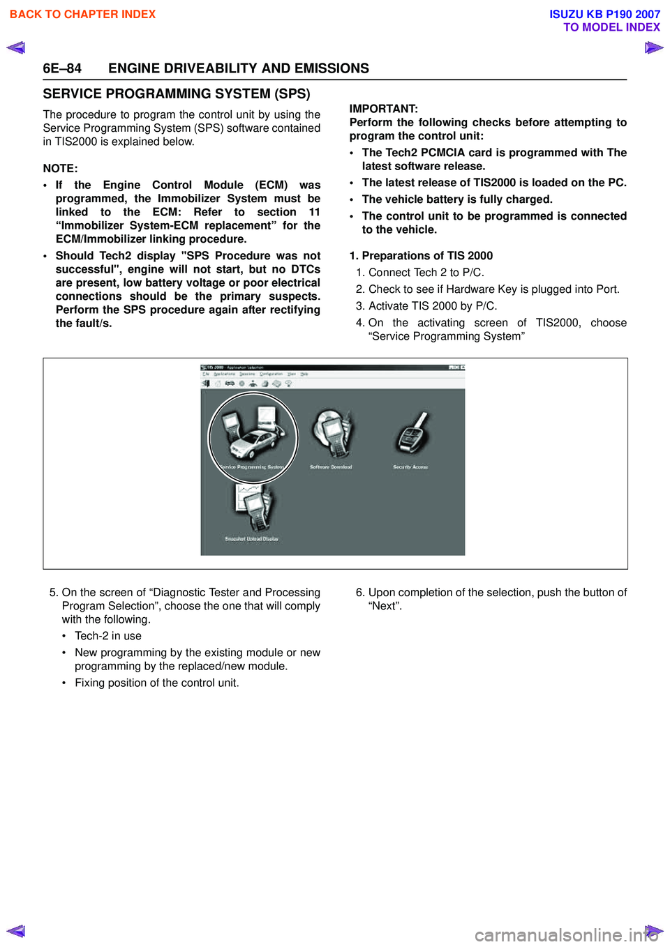
SERVICE PROGRAMMING SYSTEM (SPS)
The procedure to program the control unit by using the
Service Programming System (SPS) software contained
in TIS2000 is explained below.
NOTE:
• If the Engine Control Module (ECM) was programmed, the Immobilizer System must be
linked to the ECM: Refer to section 11
“Immobilizer System-ECM replacement” for the
ECM/Immobilizer linking procedure.
• Should Tech2 display "SPS Procedure was not successful", engine will not start, but no DTCs
are present, low battery voltage or poor electrical
connections should be the primary suspects.
Perform the SPS procedure again after rectifying
the fault/s. IMPORTANT:
Perform the following checks before attempting to
program the control unit:
• The Tech2 PCMCIA card is programmed with The latest software release.
• The latest release of TIS2000 is loaded on the PC.
• The vehicle battery is fully charged.
• The control unit to be programmed is connected to the vehicle.
1. Preparations of TIS 2000 1. Connect Tech 2 to P/C.
2. Check to see if Hardware Key is plugged into Port.
3. Activate TIS 2000 by P/C.
4. On the activating screen of TIS2000, choose “Service Programming System”
5. On the screen of “Diagnostic Tester and Processing Program Selection”, choose the one that will comply
with the following.
• Tech-2 in use
• New programming by the existing module or new programming by the replaced/new module.
• Fixing position of the control unit. 6. Upon completion of the selection, push the button of
“Next”.
BACK TO CHAPTER INDEX
TO MODEL INDEX
ISUZU KB P190 2007
Page 2431 of 6020
ENGINE DRIVEABILITY AND EMISSIONS 6E–261
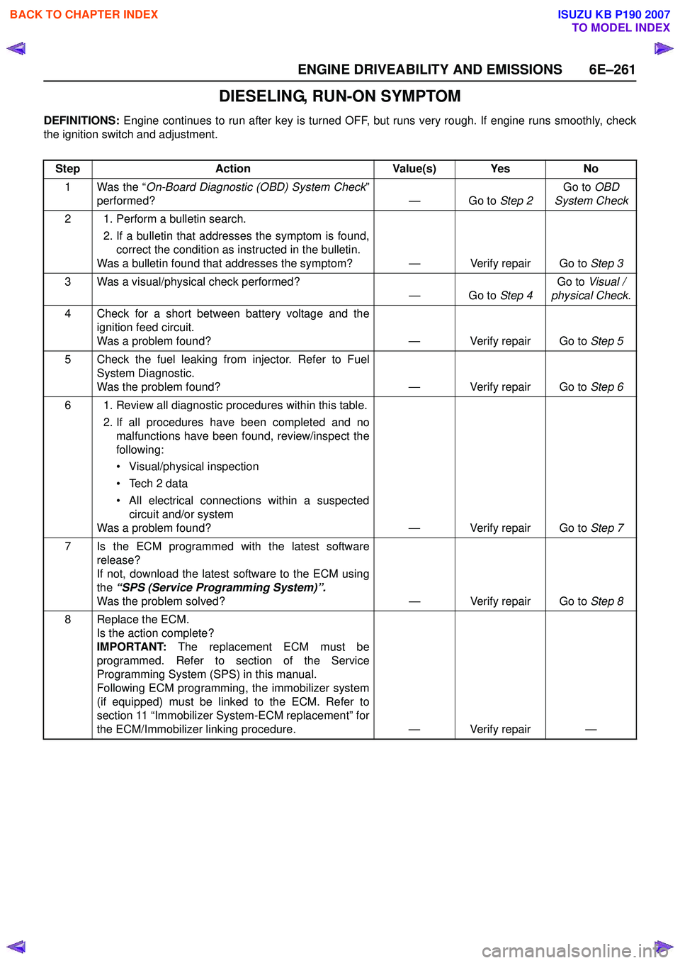
DIESELING, RUN-ON SYMPTOM
DEFINITIONS: Engine continues to run after key is turned OFF, but runs very rough. If engine runs smoothly, check
the ignition switch and adjustment.
Step Action Value(s) Yes No
1 Was the “ On-Board Diagnostic (OBD) System Check ”
performed? — Go to Step 2Go to
OBD
System Check
2 1. Perform a bulletin search. 2. If a bulletin that addresses the symptom is found,correct the condition as instructed in the bulletin.
Was a bulletin found that addresses the symptom? — Verify repair Go to Step 3
3 Was a visual/physical check performed? —Go to Step 4Go to
Visual /
physical Check .
4 Check for a short between battery voltage and the ignition feed circuit.
Was a problem found? — Verify repair Go to Step 5
5 Check the fuel leaking from injector. Refer to Fuel System Diagnostic.
Was the problem found? — Verify repair Go to Step 6
6 1. Review all diagnostic procedures within this table. 2. If all procedures have been completed and nomalfunctions have been found, review/inspect the
following:
• Visual/physical inspection
• Tech 2 data
• All electrical connections within a suspected circuit and/or system
Was a problem found? — Verify repair Go to Step 7
7 Is the ECM programmed with the latest software release?
If not, download the latest software to the ECM using
the “SPS (Service Programming System)”.
Was the problem solved? — Verify repair Go to Step 8
8 Replace the ECM. Is the action complete?
IMPORTANT: The replacement ECM must be
programmed. Refer to section of the Service
Programming System (SPS) in this manual.
Following ECM programming, the immobilizer system
(if equipped) must be linked to the ECM. Refer to
section 11 “Immobilizer System-ECM replacement” for
the ECM/Immobilizer linking procedure. — Verify repair —
BACK TO CHAPTER INDEX
TO MODEL INDEX
ISUZU KB P190 2007
Page 3325 of 6020
Engine Management – V6 – Diagnostics Page 6C1-2–47
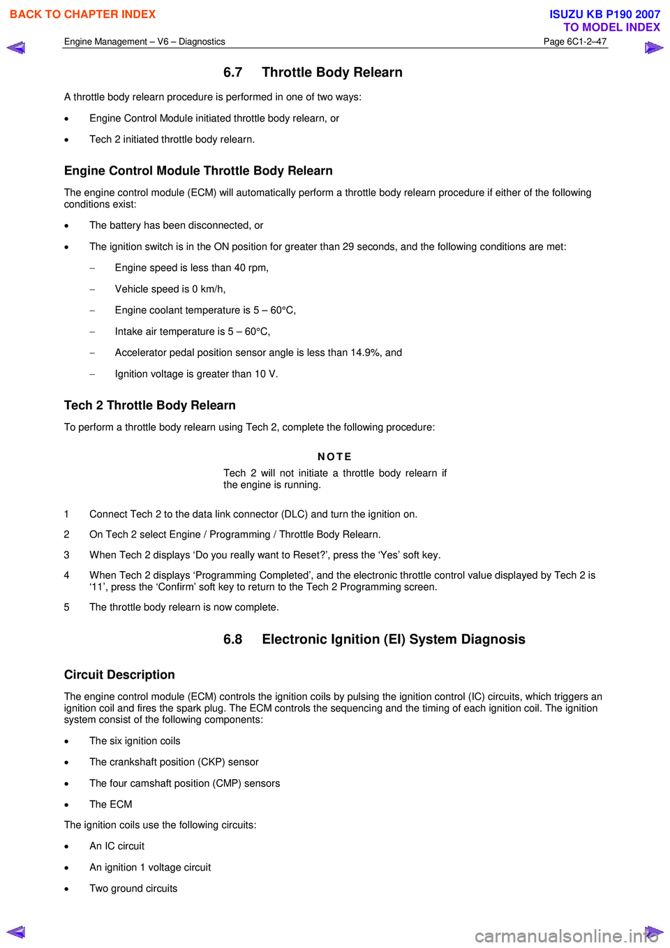
6.7 Throttle Body Relearn
A throttle body relearn procedure is performed in one of two ways:
• Engine Control Module initiated throttle body relearn, or
• Tech 2 initiated throttle body relearn.
Engine Control Module Throttle Body Relearn
The engine control module (ECM) will automatically perform a throttle body relearn procedure if either of the following
conditions exist:
• The battery has been disconnected, or
• The ignition switch is in the ON position for greater than 29 seconds, and the following conditions are met:
− Engine speed is less than 40 rpm,
− Vehicle speed is 0 km/h,
− Engine coolant temperature is 5 – 60°C,
− Intake air temperature is 5 – 60°C,
− Accelerator pedal position sensor angle is less than 14.9%, and
− Ignition voltage is greater than 10 V.
Tech 2 Throttle Body Relearn
To perform a throttle body relearn using Tech 2, complete the following procedure:
NOTE
Tech 2 will not initiate a throttle body relearn if
the engine is running.
1 Connect Tech 2 to the data link connector (DLC) and turn the ignition on.
2 On Tech 2 select Engine / Programming / Throttle Body Relearn.
3 W hen Tech 2 displays ‘Do you really want to Reset?’, press the ‘Yes’ soft key.
4 W hen Tech 2 displays ‘Programming Completed’, and the electronic throttle control value displayed by Tech 2 is ‘11’, press the ‘Confirm’ soft key to return to the Tech 2 Programming screen.
5 The throttle body relearn is now complete.
6.8 Electronic Ignition (EI) System Diagnosis
Circuit Description
The engine control module (ECM) controls the ignition coils by pulsing the ignition control (IC) circuits, which triggers an
ignition coil and fires the spark plug. The ECM controls the sequencing and the timing of each ignition coil. The ignition
system consist of the following components:
• The six ignition coils
• The crankshaft position (CKP) sensor
• The four camshaft position (CMP) sensors
• The ECM
The ignition coils use the following circuits:
• An IC circuit
• An ignition 1 voltage circuit
• Two ground circuits
BACK TO CHAPTER INDEX
TO MODEL INDEX
ISUZU KB P190 2007